Graphitronic - Commercial Washing Machines Tumble Dryers ...
Graphitronic - Commercial Washing Machines Tumble Dryers ...
Graphitronic - Commercial Washing Machines Tumble Dryers ...

Create successful ePaper yourself
Turn your PDF publications into a flip-book with our unique Google optimized e-Paper software.
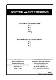
INDUSTRIAL WASHER EXTRACTORSHIGH SPIN WASHER EXTRACTORS:6 kg 16 kg 40 kg7 kg 22 kg 55 kg10 kg 22 kg PRO 80 kg13 kg 33 kg 120 kgRIGID MOUNTED WASHER EXTRACTORS:6 kg 18 kg7 kg 22 kg10 kg 27 kg13 kg 35 kgHIGH SPIN HYGIENIC BARRIER WASHER EXTRACTORS:16 kg 70 kg26 kg 90 kg33 kg 110 kg44 kg 140 kg66 kg 180 kgPROGRAMMING MANUAL GRAPHITRONIC531486 APublication date: 6 Oct 2009
Machine type selection:Dry loadcapacity„Machine type“selection6 kg / 15 lbs => R67 kg / 18 lbs => R710 kg / 25 lbs => R10Rigid mountedindustrial washerextractors13 kg / 30 lbs => R1318 kg / 40 lbs => R18High spin industrialwasher extractorsHigh spin hygienicbarrier washerextractors22 kg / 50 lbs => R2227 kg / 60 lbs => R2735 kg / 80 lbs => R356 kg / 15 lbs => F67 kg / 18 lbs => F710 kg / 25 lbs => F1013 kg / 30 lbs => F1316 kg / 35 lbs => F1622 kg / 50 lbs => F23/322 kg / 50 lbs => F23/433 kg / 80 lbs => F3340 kg / 100 lbs => F4055 kg / 125 lbs => F5580 kg / 180 lbs => F80120 kg / 270 lbs => F12016 kg / 35 lbs => MB1626 kg / 60 lbs => MB2633 kg / 80 lbs => MB3344 kg / 110 lbs => MB4466 kg / 150 lbs => MB6670 kg / 160 lbs => MB7090 kg / 200 lbs => MB90110 kg / 245 lbs => MB110140 kg / 310 lbs => MB140180 kg / 400 lbs => MB180<strong>Machines</strong> with plasticsoap dispenser<strong>Machines</strong> with stainlesssteel soap dispenser
CONTENTS1. TABLE OF CONTENTS1. TABLE OF CONTENTS.................................................................................................. 12. WARNINGS AND SYMBOLS ......................................................................................... 32.1. WARNINGS ......................................................................................................................................32.2. SYMBOLS USED..............................................................................................................................43. BASIC DESCRIPTION OF CONTROLS......................................................................... 63.1. GENERAL.........................................................................................................................................63.2. SPECIFIC .........................................................................................................................................73.3. HOW TO GET INTO THE SETUP MODE..........................................................................................83.4. THE CREATION OF A WASH PROGRAM ......................................................................................103.5. PROGRAMMING THE FUNCTIONS ...............................................................................................124. INITIALIZING THE MACHINE....................................................................................... 234.1 INITIALISATION MENU ...................................................................................................................234.2 CONFIGURATION MENU................................................................................................................284.3 ADVANCED MENU..........................................................................................................................355. PROGRAMMING........................................................................................................... 445.1 GENERAL........................................................................................................................................445.2. STEP : PROGRAM MENU..........................................................................................................445.3. STEP : PROGRAM FUNCTIONS................................................................................................455.4. STEP : PROGRAM STEP FUNCTION........................................................................................475.5. STEP : PROGRAMMING THE WASH PART ..............................................................................485.6. STEP : PROGRAMMING THE DRAIN STEP..............................................................................586. OPERATION MENU...................................................................................................... 616.1. STARTING UP................................................................................................................................616.2. SWITCHING ON THE POWER .......................................................................................................616.3. LOAD THE WASHING MACHINE ...................................................................................................616.4. PUT SOAP INTO THE SOAPHOPPER ...........................................................................................616.5. STARTING A WASH PROGRAM ....................................................................................................616.6. PROGRAMMING A DELAY TIME...................................................................................................626.7. ECONOMIC ....................................................................................................................................626.8. THE ACTIVE PROGRAM................................................................................................................626.9. ADVANCING A WASH PROGRAM .................................................................................................636.10. WASH TIME..................................................................................................................................636.11. PROGRAM END ...........................................................................................................................636.12. WATER FILL PROCESS...............................................................................................................656.13. HEATING PROCESS....................................................................................................................656.14. COOLDOWN FUNCTION..............................................................................................................666.15. FLUSH FUNCTION .......................................................................................................................666.16. SPRAY FUNCTION.......................................................................................................................666.17. UNBALANCE ................................................................................................................................666.18. PAUSE..........................................................................................................................................666.19. STOP............................................................................................................................................676.20. OPEN SOAP BOX.........................................................................................................................676.21. WAIT STATE.................................................................................................................................676.22. HOW TO HANDLE FAILURE MESSAGES....................................................................................676.23. HOW TO HANDLE POWER INTERUPTIONS ...............................................................................686.24. SPECIAL FUNCTION BUTTONS ..................................................................................................69531486_A_PUB_DATE_6_OCT_2009.DOC PROGRAMMING MANUAL 1
6.25. WATER RECYCLING................................................................................................................... 706.26. SOAP BOXES .............................................................................................................................. 706.27. WEIGHING SYSTEM.................................................................................................................... 707. PRE-PROGRAMMED PROGRAMS..............................................................................727.1. LEGEND ........................................................................................................................................ 727.2. WASH PROGRAMS....................................................................................................................... 73 Wash program 1: HOT WASH - 90°C................................................................................................. 73 Wash program 2: WARM WASH - 60°C............................................................................................. 73 Wash program 3: COLORED WASH - 40°C....................................................................................... 74 Wash program 4: BRIGHT COLORED WASH - 30°C......................................................................... 74 Wash program 5: WOOLENS - 15°C.................................................................................................. 75 Wash program 6: ECO HOT WASH - 90°C ........................................................................................ 75 Wash program 7: ECO WARM WASH - 60°C .................................................................................... 76 Wash program 8: ECO COLORED WASH - 40°C .............................................................................. 76 Wash program 9: ECO BRIGHT COLORED WASH - 30°C ................................................................ 77 Wash program 10: SUPER ECO HOT WASH - 90°C ......................................................................... 77 Wash program 11: SUPER ECO WARM WASH - 60°C...................................................................... 78 Wash program 12: SUPER ECO COLOR WASH - 40°C ................................................................... 78 Wash program 13: SUPER ECO BRIGHT COLOR WASH - 30°C ...................................................... 79 Wash program 14: EXTRACTION - LOW SPEED ............................................................................. 79 Wash program 15: EXTRACTION - HIGH SPEED ............................................................................ 798. TROUBLESHOOTING...................................................................................................808.1. DISPLAY MESSAGES.................................................................................................................... 808.2. FAULT MESSAGES ....................................................................................................................... 808.3. HOW TO HANDLE FAULT MESSAGES......................................................................................... 818.4. OVERVIEW.................................................................................................................................... 838.5. SERVICE MENU ............................................................................................................................ 868.6. DIAGNOSTIC PROGRAM .............................................................................................................. 898.7. PROBLEM CHECK LIST ................................................................................................................ 938.8. EXPLANATION ERROR MESSAGES ............................................................................................ 949. SERVICE INFORMATION ...........................................................................................1219.1. MAINTENANCE ........................................................................................................................... 1219.2. INFORMATION FOR SERVICE.................................................................................................... 1219.3. PROGRAMMER CIRCUIT BOARD............................................................................................... 1229.4. INSTRUCTIONS FOR REPLACING THE ELECTRONIC BOARD AND KEYPAD ......................... 1229.5. INSTRUCTIONS FOR INSTALLING NEW SOFTWARE ............................................................... 12310. SPECIFICATION OF YOUR MACHINE.....................................................................1242 PROGRAMMING MANUAL 531486_A_PUB_DATE_6_OCT_2009.DOC
INTRODUCTION2. WARNINGS AND SYMBOLS2.1. WARNINGSBEFORE OPERATING A MACHINE CONTROLLED BY AN ELECTRONIC PROGRAMMER, READ THISMANUAL. INCORRECT USE CAN RESULT IN SERIOUS INJURIES OR DAMAGE TO THE MACHINECONTROLS. IGNORING INSTRUCTIONS CAN CAUSE AN INCORRECT MACHINE FUNCTION, WHICHMAY RESULT IN INJURIES OR MACHINE AND/OR LINEN DAMAGES.– This manual version is an original English version. Without the original version these instructions are notcomplete. Before installation, operating and maintenance of the machine, read complete instructionsthoroughly which means the following manuals: „Programming Manual“, „User‘s Manual“ and „Installationand Maintenance Manual“. Follow these instructions and keep them handy for later use.– A machine must be installed by following the „Installation and maintenance manual“. Before the first machinestart, it must be initialized and tested by a qualified worker. When operating the machine, follow themachine „Users Manual“.– The electric service line must not be affected by other electrical loading. A nominal voltage, if loaded or notmust work in the range ±10% with a maximum permanent frequency deviation of 1% or a short-time one at2% of a given frequency (50 or 60 Hz). Connecting or starting the machine at an incorrect voltage candamage the programmer.– The machine must not be exposed to high humidity or extreme high and low temperatures.– Do not tamper with the controls.INSTRUCTIONS IN THIS MANUAL DO NOT COVER ALL DANGEROUS SITUATIONS.IT IS UP TO THE USER TO HANDLE THE MACHINE CAREFULLY.The manufacturer has the right to change specifications in this manual without prior notice. All the statedinformation is only for informative purpose and must be considered as general. It is not possible to present allthe specific data of the device.NOTE!EVERY CIRCUIT BOARD HAS A SERIAL NUMBER AND THE CODE OF THE BOARD (Picture 9.3).ON THE EPROM MEMORY CHIP ON THE CIRCUIT BOARD IS A LABEL SPECIFYING THE SOFTWARENUMBER AND VERSION AND/OR THE DATE OF THE SOFTWARE (Picture 9.3).THESE DATA, AS WELL AS THE MODEL AND SERIAL NUMBER OF THE MACHINE, MUST BEMENTIONED IN ALL CORRESPONDENCE OR INQUIRIES ADDRESSED TO THE DISTRIBUTOR ORMANUFACTURER.NOTE!THE “GRAPHITRONIC“ COMPUTER USES ‘MACHINE TYPE’ CODES TO SELECT THE DIFFERENTPROGRAMMABLE MACHINES EXECUTIONS.The model number on the machine doesn’t indicate the ‘machine type’ but must be linked with thedescription of the ‘machine type’ letters.RS : Rigid mounted Frequency inverter driven machines (MFRxxPNC)FS : Free standing Frequency inverter driven machines (MFSxxPNF)MB : Medical Barrier machines.531486_A_PUB_DATE_6_OCT_2009.DOC PROGRAMMING MANUAL 3
2.2. SYMBOLS USED BUTTONSOPERATION BUTTONS• 1 2 3 4 5 6 7 8 9 0- Program number selection buttonsPROGRAM BUTTONS• ARROW UP- Selecting the previous menu item100955• START- Starting up a program- Advancing the program step by step• STOP- Interrupting a program- Finishing a program• YES- Yes selection• NO- No selection100947100948100949100950• ARROW DOWN- Selecting the next menu item• ARROW LEFT- Selecting the previous element of a menu item list• ARROW RIGHT- Selecting the next element of a menu item list• ENTER- Selecting a new menu- Confirmation of a new value or list element andgoing over to the next menu item100956100951100952100957• ARROW LEFT- Decreasing the sequence time100951• YES- Yes Selection100949• ARROW RIGHT- Increasing the sequence time• INFO- shows all available wash programs, programsteps and functions• SERVICE- shows the status and the total number of machinecycles• DELAY TIME- activates the time delay function100952100953100954• NO- No Selection• 1 2 3 4 5 6 7 8 9 0- Numeric values- Numeric DotSPECIAL FUNCTION BUTTONS• INLET 1 2 3 ( 4 5 6 )- Open the inlet valve• HEATING- Activate the heating ( if equipped)• DRAINAGE- Open the Drain valve• SPEED ADJUST- Change the speed value100950100800100958100959100960100961 LABELSOn the labels you can find Instructions for the <strong>Washing</strong> machine Operation and Informationabout the Wash Programs. EMERGENCY STOP SWITCHThis emergency stop switch is used by non-coin washer-extractors4 PROGRAMMING MANUAL 531486_A_PUB_DATE_6_OCT_2009.DOC
INTRODUCTION531486_A_PUB_DATE_6_OCT_2009.DOC PROGRAMMING MANUAL 5
3. BASIC DESCRIPTION OF CONTROLS3.1. GENERAL THE CONTROL OFFERS :• 99 programmable programs (including 15 pre-programmed ones).• Control of signal voltages for external pumps or liquid supply dispensers.• Redistribution of the garments to avoid imbalance.• Automatic temperature balance during the water fill process.• Setting the machine options and configuration.• Multiple languages can be selected (one at a time). IN OPERATION THE FOLLOWING DATA IS DISPLAYED :• The selected program.• The active wash step.• The remaining program time.• Wash cycle progression bar.• The name of the sequence.• Indication of wait for heat (if selected).• Symbol for water filling.• Symbol for heating.• The water level and temperature can be viewed.• Diagnostic messages. THE OPERATION MENU :• A program can be manually Shortened, Extended, Stopped.• A pause can be programmed.• Special function buttons allow direct operation of selected components (water valves, etc.).• Program overview.• Service information. THE HARDWARE AND SOFTWARE OF THE GRAPHITRONIC WASH COMPUTER :• Easy operation by a comprehensive keypad.• The hardware contains 1 electronic board.• The GRAPHITRONIC wash computer with Graphic LCD display.• The wash machine control software is implemented in a Flash Memory and can be easily replaced.• The Wash Programs are kept in EEPROM memory (non-volatile memory).6 PROGRAMMING MANUAL 531486_A_PUB_DATE_6_OCT_2009.DOC
3.2. SPECIFIC The PROGRAM Menu is designated for:• the creation of a specific name for a wash program.• the creation and implementation of a new wash program step by step.• editing a wash program step by step.• inserting and deleting steps in the wash program.• copying a wash program.• deleting a wash program.• inspecting the wash program by the view function.INTRODUCTION The CONFIGURATION Menu is designated for :• the selection of the machine type.• loading the default factory settings for the CONFIGURATION and INITIALIZATION menu.• the selection of the Brightness of the display.• the selection of the power supply voltage of the washing machine.• loading the frequency inverter parameters.• erasing all the programmed wash programs (reset Wash program EEPROM memory).• loading the standard wash programs.• the selection of the number of wash machine water supply inlets.• the selection of a second drain valve. (water recycling system)• the selection if the supply has to function as soap box or liquid.• the selection if external liquid pumps have been connected to the washing machine.• the selection if the temperature must be displayed in degrees Celsius or degrees Fahrenheit.• the selection Full Heating.• the selection Low Water Pressure• the selection of Wet Cleaning (very low programmable water levels).• the selection of the minimum level start supplies.• the selection of the number of compartments drum for big MB-machines. The INITIALIZATION Menu is designated for :• the selection of the displayed Language.• programming the Service due value.• the selection of the Buzzer time interval.• the selection of the Advance function.• the selection of the Wait for temperature function.• the selection of the Manual override function.• the selection of the Temperature balance function.• programming the Default Motor On and Off times for reversing wash action.• the selection of the Automatic Cool-down function.• the selection of the Show Economic function.• programming the Boiler temperature (hot water supply).• programming the Temperature Overshoot Protection value.• programming the Maximum Heating time value.• programming the Maximum Fill time value.• programming the Maximum Level overfill value. The SERVICE Menu is designated for :• the inspection of the error messages log register and the list with statistics.• activating the power of the frequency inverter.• the inspection of the functionality of the electric input signals.• resetting the Cycle counter. The DIAGNOSTIC Menu is designated for :• running a Diagnostic Program. The ADVANCED Menu is designated for :• special optional applications531486_A_PUB_DATE_6_OCT_2009.DOC PROGRAMMING MANUAL 7
3.3. HOW TO GET INTO THE SETUP MODEFor machine with a key switchTurn the key switch to the setup mode.– RUN MODE: This is the Normal wash machine operation.– PROGRAM MODE: Only for changing the wash programs and machine settings.For machines without a key switch (RS6..RS35, FS6..FS23)Press the Status Button on the keypad.Press the Arrow Down Button several times until you see the screen with the Menu Selection:"To Program Mode No/Yes"Status MenuTo Program ModeNo/YesSelect "Yes" and by pressing the Enter Button, you will see the Main Menu Screen.If a Password was enabled first you have to Enter the right Password.To Program ModePassword ....How to leave a setup modeWhen the "Main Menu" screen is shown.Press the Status Button on the keypad. Then you will return to 'Run Mode" and"SELECT CYCLE" is shown.8 PROGRAMMING MANUAL 531486_A_PUB_DATE_6_OCT_2009.DOC
INTRODUCTION99 Wash Programs – 99 StepsProgram 1 Program 2 Program 3 . . . Program 99Name Prog Name Prog Name Prog Name ProgStep 1 Step 1 Step 1 . . . Step 1WashSequenceWashSequenceWashSequenceWashSequenceDrain/Drain/Drain/Drain/ExtractionExtractionExtractionExtractionSequenceSequenceSequenceSequenceStep 2 Step 2 . . . Step 2WashSequenceWashSequenceWashSequenceDrain/ExtractionSequenceDrain/ExtractionSequenceDrain/ExtractionSequenceStep 3 . . . Step 3WashSequenceWashSequenceDrain/ExtractionSequenceDrain/ExtractionSequence. . . . . .Step 99 Step 99WashSequenceWashSequenceDrain/Drain/ExtractionExtractionSequenceSequence<strong>Tumble</strong>Sequence<strong>Tumble</strong>Sequence<strong>Tumble</strong>Sequence. . . <strong>Tumble</strong>SequenceAvailable Wash Sequences : Prewash, Wash, Cooldown, Rinse, Final Rinse, Soak, Flush, Spray, No WashAVAILABLE DRAIN/EXTRACTION SEQUENCES : DRAIN, EXTRACT, NO DRAIN, STATIC DRAIN, REV DRAIN531486_A_PUB_DATE_6_OCT_2009.DOC PROGRAMMING MANUAL 9
3.4. THE CREATION OF A WASH PROGRAM• a Wash Program is built up step by step.• each step always consists of a Wash sequence and a Drain/Extraction sequence. Top soap dispenser and Front soap dispenser washing machines :-• The GRAPHITRONIC Wash Computer is designated for 2 Main groups of washing machines:- The washing machines with Top Soap Dispenser- The washing machines with Front Soap Dispenser• Depending upon the machine type, more or less machine functions are available. Programming the Wash sequence :• First choose the type of Wash sequence.<strong>Washing</strong> machine withTop Soap Dispenser<strong>Washing</strong> machine withFront (or side) Soap Dispenser• PREWASH• WASH• COOLDOWN• RINSE• FINAL RINSE• FLUSH• SOAK• SPRAY• No WASH• WASH• COOLDOWN• RINSE• SOAK• SPRAY• No WASH• Then program all the related functions of the sequence.The available functions are :• Temperature• Water Level• Water Inlet Valves• The Wash Speed• The Reversing Interval times• Supplies• Sequence Time ( length of step )• Drain valve 1 – 2• Pause Signal10 PROGRAMMING MANUAL 531486_A_PUB_DATE_6_OCT_2009.DOC
INTRODUCTION• You will notice that each step has default settings.This feature is very helpful as most of the newly created programs will not require changes to bemade to the suggested values. Programming the Drain sequence :• After programming the Wash sequence, next program the Drain/Extraction sequence.<strong>Washing</strong> <strong>Machines</strong>with 1 motor• DRAIN• EXTRACTION• No DRAIN• Static DRAIN• Reversing DRAIN• Then program all the related functions of the Drain/Extraction sequence.The available functions are :• Sequence Time ( length of step )• Speed• Drain valve 1 – 2• As you will notice it’s also possible to skip a sequence between two other sequences byprogramming No WASH or No Drain.Example : The No drain sequence should be programmed between a wash and a cool-downsequence.! ATTENTION!A MORE DETAILED EXPLANATION FOR THE SPECIFIC SEQUENCES CAN BE FOUND IN CHAPTER 5. The <strong>Tumble</strong> sequence :• The wash cycle will always end with the <strong>Tumble</strong> sequence.• The tumble sequence takes 30 Seconds, then the program is finished and the door can be opened.• The <strong>Tumble</strong> sequence cannot be skipped.531486_A_PUB_DATE_6_OCT_2009.DOC PROGRAMMING MANUAL 11
3.5. PROGRAMMING THE FUNCTIONS Limits• To ensure the correct functionality of the washing machine you have to program values withincertain limits.• If you program a value that falls below the minimal or above the maximal programmable limitthen the new value will not be accepted and the previous value stays valid. Programming the Water Temperature• Limits- Minimum value : 1 °C- Maximum value : 45°C for the PREWASH and SOAK and 92°C for the WASH sequence.- For RINSE, FINAL RINSE, FLUSH and SPRAY no Temperature can be programmed. Programming the Water Inlet valves• Depending on the programmed temperature the water inlet valves are suggested.• While the tub is filling with water, the computer controls the water temperature. By switching onand off the hot and cold water inlet valves the correct water temperature is obtained.• For machines with a Top Soap Dispenser you have to consider that by programming the water inletvalves, at the same time, you are also selecting the soap Box at which the soap must be added.• If you want to program a wash sequence with :- Cold Water : only Cold Inlet Valves must be programmed- Warm or Hot water : Cold and Hot Inlet Valves must be programmedTop Soap Dispenser washing machines: MFRThe cold water inlet valvesInlet Valve 2 corresponds with Soap Box A (Prewash)Inlet Valve 5 corresponds with Soap Box B (Wash)Inlet Valve 1 corresponds with Soap Box C (Final Rinse)Inlet Valve 6 is a direct Inlet Valve and speeds up the water fill processThe hot water inlet valvesInlet Valve 4 corresponds with Soap Box B (Wash)Inlet Valve 3 is a direct inlet Valve and speeds up the water fill processHow to select inlet valves : EXAMPLE• For a Prewash : Programmable temperature: 1 - 45°CInlet Valve 2 (cold)Soap box A+ Inlet Valve 3 (hot) and/or 6 (cold) Direct Inlets• For a Wash : Programmable temperature: 1 - 92°CInlet Valve 4 (hot) and/or 5 (cold) Soap box B+ Inlet Valve 3 (hot) and/or 6 (cold) Direct Inlets• For a Rinse : Inlet valves 2 + 5 + 6 (cold) No Soap is added• For a Final Rinse : Inlet valve 1 (cold hard) (or cold soft) Soap box C+ Inlet valve 6 (cold soft) only if No cold hard water for Inlet 112 PROGRAMMING MANUAL 531486_A_PUB_DATE_6_OCT_2009.DOC
INTRODUCTION! ATTENTION!FOR MACHINES WITH LIQUID SUPPLY PUMPS, DIRECT WATER INLET VALVES 3 OR 6 MUST BEPROGRAMMED BECAUSE THE LIQUID IS ADDED AT THE DIRECT WATER INLET CHANNEL.DEPENDING ON THE WASHING MACHINE EXECUTION, WATER INLET VALVE 1 WILL FUNCTIONWITH COLD WATER.FOR WASHING MACHINES WITH WATER RECYCLING, THE WATER RECYCLING SUPPLY MUSTBE CONNECTED TO INLET VALVE 2 OR 5Front or Side Soap Dispenser washing machines :The cold water inlet valvesInlet Valve 1 : Cold Hard Water or Recycled WaterInlet Valve 2 : Cold Soft WaterThe hot water inlet valveInlet Valve 3 : Warm Soft Water! ATTENTION!FOR A FRONT SOAP DISPENSER WASHING MACHINE, TO ADD SOAP, THE SUPPLIES MUST BE PROGRAMMED. Programming the water level!– Water level Limits• See table 3.4 A and 3.4 B as these values are different for each machine type.• Minimum value : above the heating elements and the temperature sensor• Maximum value : below the overflow outlet– Normal Low Level, Normal High Level• The Normal Low Level is recommended for the PREWASH, WASH and SOAK sequences.• The Normal High Level is recommended for the RINSE and FINAL RINSE Sequences.• At the FLUSH sequence, you can’t program a water level as the water will escape by theoverflow opening.• At the COOLDOWN sequence, the GRAPHITRONIC Wash Computer makes use of a low waterlevel and is draining the water automatically.• At the Spray sequence, the Drain valve stays open.– Economic water level• If you prefer a wash cycle with an economic water level :– you can select “Show ECONOMIC” in the initialization menu to make use of the standardECONOMIC function. Then at the start of each wash cycle, the question ECONOMIC?will be posed. If you select ECONOMIC then the program will function with 20% units less water.– or you may make dedicated programs with a water level 20% units below the Normalwater level.– Wet Cleaning selection Configuration menuATTENTION!• It’s possible to program a level below default minimum programmable level. (see table)• The heating will not be functional for a water level below the standard minimumprogrammable water level.FOR WOOLENS AND OTHER DELICATE LINEN A NORMAL HIGH WATER LEVEL IS RECOMMENDED.THE ECONOMIC FUNCTION SHOULD ONLY BE USED FOR LIGHTLY SOILED AND/OR SMALLERVOLUMES OF LAUNDRY. IN OTHER CASES, THE PROGRAM WILL GIVE POOR WASHING QUALITY.531486_A_PUB_DATE_6_OCT_2009.DOC PROGRAMMING MANUAL 13
Machinetype15Programmable water level units relatedto the amount of water in the tubRS6 RS7 RS10 RS13 RS18 RS22 RS27 RS3516 9 l 10 l 14 l17 10 l 11 l 15 l 16 l18 11 l 12 l 16 l 17 l19 12 l 13 l 17 l 19 l20 13 l 14 l 18 l 21 l 19 l 27 l21 14 l 15 l 19 l 23 l 22 l 32 l22 15 l 16 l 22 l 25 l 25 l 37 l 49 l23 17 l 18 l 25 l 28 l 28 l 42 l 55 lProgrammed water LEVEL (Water level height in units)24 18 l 20 l 28 l 31 l 31 l 47 l 61 l25 19 l 22 l 31 l 34 l 35 l 52 l 50 l 67 l26 21 l 24 l 34 l 37 l 38 l 57 l 55 l 73 l27 23 l 26 l 36 l 40 l 41 l 62 l 60 l 78 l28 25 l 29 l 38 l 43 l 44 l 67 l 65 l 83 l29 27 l 32 l 41 l 46 l 48 l 72 l 70 l 89 l30 28 l 34 l 43 l 49 l 52 l 77 l 76 l 95 l31 30 l 36 l 45 l 52 l 56 l 83 l 81 l 101 l32 32 l 38 l 48 l 55 l 60 l 89 l 86 l 107 l33 33 l 40 l 51 l 58 l 63 l 95 l 91 l 113 l34 35 l 42 l 54 l 60 l 67 l 101 l 96 l 119 l35 37 l 45 l 57 l 63 l 71 l 107 l 101 l 125 l36 39 l 47 l 59 l 66 l 75 l 113 l 106 l 131 l37 41 l 49 l 61 l 69 l 79 l 119 l 111 l 137 l38 43 l 51 l 64 l 72 l 83 l 125 l 116 l 144 l39 45 l 53 l 66 l 76 l 87 l 131 l 121 l 150 l40 47 l 55 l 68 l 79 l 91 l 137 l 127 l 157 l41 83 l 96 l 143 l 132 l 164 l42 86 l 100 l 149 l 137 l 170 l43 89 l 104 l 155 l 142 l 177 l44 92 l 108 l 161 l 148 l 184 l45 95 l 113 l 167 l 153 l 192 l46 117 l 173 l 159 l 198 l47 121 l 179 l 164 l 204 l48 125 l 185 l 170 l 210 l49 129 l 191 l 175 l 216 l50 133 l 197 l 181 l 223 l51 187 l 230 l52 192 l53 198 l54 203 l55 208 l56 214 l57 220 l58 225 l59 231 l60 236 l Economic Low Level Economic High Level Normal Low Level Normal High Level14 PROGRAMMING MANUAL 531486_A_PUB_DATE_6_OCT_2009.DOC
INTRODUCTIONMachinetypeProgrammable water level units relatedto the amount of water in the tubFS6 FS7 FS10 FS13 FS16 FS22 FS2315 9 l 10 l16 10 l 10 l 12 l17 10 l 11 l 12 l18 11 l 12 l 13 l 14 l 15 l19 12 l 13 l 14 l 16 l 17 l20 13 l 14 l 15 l 18 l 19 l 24 l21 14 l 15 l 17 l 20 l 22 l 27 l22 16 l 17 l 20 l 23 l 25 l 30 l23 17 l 18 l 23 l 25 l 28 l 34 lProgrammed water LEVEL (Water level height in units)24 18 l 20 l 25 l 27 l 31 l 37 l25 20 l 22 l 28 l 30 l 34 l 41 l26 22 l 24 l 31 l 33 l 37 l 45 l27 24 l 26 l 33 l 36 l 40 l 49 l28 26 l 28 l 36 l 38 l 43 l 29 l 53 l29 28 l 31 l 38 l 41 l 46 l 33 l 57 l30 30 l 33 l 40 l 44 l 49 l 37 l 61 l31 32 l 35 l 43 l 47 l 53 l 41 l 65 l32 33 l 37 l 46 l 50 l 57 l 45 l 69 l33 35 l 39 l 48 l 53 l 60 l 49 l 73 l34 37 l 41 l 50 l 56 l 63 l 53 l 78 l35 38 l 44 l 53 l 59 l 67 l 57 l 83 l36 40 l 46 l 55 l 62 l 70 l 61 l 88 l37 42 l 48 l 58 l 65 l 74 l 66 l 92 l38 43 l 51 l 61 l 68 l 78 l 71 l 96 l39 45 l 53 l 63 l 72 l 81 l 75 l 101 l40 47 l 55 l 65 l 75 l 84 l 79 l 106 l41 78 l 88 l 83 l 111 l42 81 l 91 l 87 l 115 l43 85 l 95 l 91 l 119 l44 88 l 99 l 95 l 124 l45 91 l 103 l 100 l 129 l46 94 l 107 l 105 l 134 l47 97 l 111 l 110 l 139 l48 100 l 114 l 114 l 144 l49 118 l 119 l 149 l50 122 l 124 l 153 l51 124 l 129 l 157 l52 127 l 134 l 162 l53 140 l 167 l54 145 l 172 l55 150 l 176 l56 155 l57 160 l58 165 l59 170 l60 175 l Economic Low Level Economic High Level Normal Low Level Normal High Level531486_A_PUB_DATE_6_OCT_2009.DOC PROGRAMMING MANUAL 15
Machine typeProgrammable water level units relatedto the amount of water in the tubFS33 FS40 FS55 FS80 MB16 MB26 MB33 MB44 MB6627 86 l28 91 l29 98 l30 105 l 30 l 32 l 30 l 59 l 97 l31 114 l 33 l 36 l 34 l 65 l 105 l32 121 l 36 l 40 l 38 l 71 l 113 l33 129 l 39 l 44 l 43 l 77 l 123 l34 138 l 42 l 48 l 48 l 83 l 133 l35 147 l 45 l 52 l 53 l 90 l 144 l36 155 l 49 l 57 l 59 l 96 l 153 l37 163 l 53 l 62 l 65 l 102 l 163 lProgrammed water LEVEL (Water level height in units)38 43 l 62 l 62 l 172 l 57 l 67 l 70 l 109 l 173 l39 47 l 66 l 66 l 181 l 61 l 72 l 75 l 116 l 184 l40 51 l 70 l 70 l 190 l 65 l 77 l 80 l 124 l 196 l41 55 l 76 l 76 l 198 l 70 l 82 l 86 l 132 l 208 l42 59 l 82 l 82 l 207 l 75 l 87 l 91 l 140 l 220 l43 63 l 88 l 88 l 215 l 80 l 92 l 95 l 148 l 234 l44 67 l 95 l 95 l 225 l 85 l 98 l 102 l 157 l 246 l45 70 l 101 l 101 l 235 l 90 l 105 l 107 l 167 l 259 l46 74 l 107 l 107 l 245 l 95 l 112 l 115 l 177 l 272 l47 78 l 115 l 115 l 255 l 100 l 119 l 123 l 188 l 286 l48 83 l 122 l 122 l 268 l 105 l 124 l 131 l 196 l 299 l49 88 l 130 l 130 l 276 l 112 l 129 l 140 l 204 l 312 l50 93 l 138 l 138 l 285 l 119 l 134 l 147 l 212 l 325 l51 97 l 144 l 144 l 294 l 126 l 140 l 156 l 221 l 339 l52 101 l 150 l 150 l 305 l 133 l 146 l 163 l 230 l 354 l53 105 l 156 l 156 l 313 l 140 l 153 l 171 l 239 l 368 l54 109 l 164 l 164 l 324 l 147 l 161 l 179 l 247 l 379 l55 114 l 172 l 172 l 334 l 154 l 170 l 188 l 255 l 390 l56 119 l 181 l 181 l 346 l 161 l 179 l 197 l 264 l 402 l57 123 l 188 l 188 l 356 l 168 l 185 l 206 l 274 l 417 l58 127 l 195 l 195 l 365 l 175 l 192 l 215 l 284 l 432 l59 132 l 203 l 203 l 376 l 182 l 199 l 225 l 294 l 448 l60 137 l 210 l 210 l 386 l 189 l 207 l 234 l 302 l 465 l61 142 l 218 l 218 l 398 l 197 l 215 l 243 l 310 l 483 l62 148 l 226 l 226 l 407 l 205 l 224 l 253 l 319 l 501 l63 153 l 233 l 233 l 419 l 213 l 231 l 262 l 328 l 517 l64 158 l 240 l 240 l 429 l 221 l 238 l 271 l 338 l 533 l65 163 l 248 l 248 l 440 l 228 l 245 l 280 l 348 l 550 l66 168 l 256 l 256 l 451 l67 173 l 265 l 265 l 464 l68 179 l 274 l 274 l 472 l69 184 l 280 l 280 l 483 l70 189 l 287 l 287 l 488 l71 195 l 294 l 294 l 499 l72 200 l 302 l 302 l 519 l73 206 l 310 l 310 l74 212 l 318 l 318 l75 216 l 326 l 326 l76 220 l 334 l 334 l77 225 l 343 l 343 l78 230 l 350 l 350 l79 235 l 358 l 358 l80 240 l 366 l 366 l Economic Low Level Economic High Level Normal Low Level Normal High Level16 PROGRAMMING MANUAL 531486_A_PUB_DATE_6_OCT_2009.DOC
Programmable water level units relatedto the amount of water in the tubMachine type FS120 MB70 MB90 MB110 MB140 MB18066 675 l 900 l 1091 l 1150 l67 688 l 918 l 1109 l 1170 l68 702 l 933 l 1127 l 1190 l69 715 l 949 l 1145 l 1210 l70 729 l 970 l 1163 l 1230 lProgrammed water LEVEL(Water level height in units)71 742 l 1181 l 1250 l72 756 l 1199 l 1270 l73 769 l 1217 l 1290 l74 783 l 1235 l 1310 l75 796 l 1253 l 1330 l76 810 l 1271 l 1350 l77 823 l 1289 l 1370 l78 837 l 1307 l 1390 l79 850 l 1325 l 1410 l80 864 l81 877 l82 891 l83 904 l84 918 l85 931 l86 945 l87 958 l88 972 l89 985 l90 999 l Economic Low Level Economic High Level Normal Low Level Normal High Level18 PROGRAMMING MANUAL 531486_A_PUB_DATE_6_OCT_2009.DOC
Wash SpeedSpin SpeedLow spinSpeedMachinetypedefaultRPMminRPMmaxRPMdefaultRPMminRPMBlockedfrequencymaxRPMdefaultRPMRS6 050 010 060 570 95 - 580 350RS7 050 010 060 570 95 - 580 350RS10 050 010 060 570 95 - 580 350RS13 045 010 055 515 85 - 525 350RS18 044 010 050 495 85 - 505 350RS22 044 010 050 470 85 - 480 350RS27 042 010 050 480 75 - 490 350RS35 038 010 045 500 75 - 510 350FS6 050 010 060 980 95 351-449 999 550FS7 050 010 060 980 95 351-449 999 550FS10 050 010 060 980 95 351-449 999 550FS13 045 010 055 980 85 351-449 999 550FS16 045 010 055 950 85 351-449 980 550FS23/3 042 010 050 860 80 351-449 915 550FS23/4 042 010 050 860 80 351-449 915 550FS22/5 042 010 050 800 80 351-449 860 550FS33 038 010 045 790 75 351-449 830 550FS40 038 010 045 790 75 351-449 830 550FS55 038 010 045 790 75 351-449 830 550FS80 036 010 045 700 75 351-449 750 550FS120 032 010 040 670 60 150-250 720 550MB16 045 010 055 940 75 351-449 960 550MB26 045 010 055 940 75 351-449 960 550MB33 045 010 055 940 75 351-449 960 550MB44 041 010 050 880 70 351-449 915 550MB66 041 010 050 880 70 351-449 915 550MB 70 036 010 045 760 65 250-380 800 550MB 90 036 010 045 760 65 250-380 800 550MB 110 035 010 045 720 65 250-380 754 550MB 140 033 010 040 690 60 150-280 720 550MB 180 036 010 040 660 60 150-280 695 550Tab. 3.4.B. Speed of machines with frequency inverter.20 PROGRAMMING MANUAL 531486_A_PUB_DATE_6_OCT_2009.DOC
INTRODUCTION Programming the Wash Speed• Standard reversing wash speed is between ≅ 40 and 50 RPM. (≅ Verify exact value at table 3.4.B.)• For some special applications the drum should only turn very slowly.- Speed Limits• The minimum programmable wash speed is 10 RPM.• The maximum programmable wash speed is 40 - 60 RPM, depending on machine size. Programming Extraction speedRS machines : Extraction ≅ 450 - 500 RPM (MFR)FS & MB machines : Extraction ≅ [300 - 350] – [450 – (850) 1000] RPM(MFS NN)• An Intermediate spin between two sequences should be about ½ of the max spin.• Between 350 and 450 RPM (≅ Verify exact value at table 3.4.B.) it’s not allowed to program a steadyspeed, as the machine could VIBRATE TOO MUCH.- Speed Limits• Check table 3.4.B with the minimum and maximum speed limits. The limits differ depending on themaximum allowed g-force at high spin for each washing machine type. Programming Supplies• Up to 4 Supplies can be programmed at the same time in a sequence.• For Front Soap Dispenser washing machines, supplies A, B, C, D and E have to be programmed toinject the soap by the boxes.• If Liquid soap pumps have been installed on the washing machine, then these pumps will beactivated by programming a time value for the corresponding supply signal 1, 2, 3, 4, 5, 6, 7, 8.- Time Limits• The maximum programmable time is 99 Seconds• If the time is 0 Seconds then the supply will NOT be activated at the wash process.! ATTENTION!IF FOR SOME SPECIAL APPLICATION MORE THAN 4 SUPPLIES MUST BE PROGRAMMED IN THESAME SEQUENCE, THIS CAN BE SOLVED BY PROGRAMMING THE SAME SEQUENCE TWICE; ONEAFTER THE OTHER. SPLIT THE WATER LEVEL ( SO IT WILL TAKE WATER FOR THE SECOND FILL,say 60%, 100%), STEP TIME, AND THE NUMBER OF SUPPLIES, OVER THE TWO SUBSEQUENTSEQUENCES. PROGRAM A “NO DRAIN” BETWEEN THE TWO SEQUENCES TO AVOID DRAININGTHE WATER. SET TEMPERATURE THE SAME FOR BOTH PARTS.531486_A_PUB_DATE_6_OCT_2009.DOC PROGRAMMING MANUAL 21
Programming the Motor On and Off times for Reversing• The standard Reversing Motor On and Off times at Wash speed is 12 Seconds On and 3 Seconds Off.• For Delicates and Woolens it’s recommended to program a gentle wash action with aReversing On time of 3 Seconds and an Off time of 12 Seconds. Programming the Sequence time.• The sequence time starts running after the water level is reached.• If wait for Temperature has been selected, the sequence time starts only running once theprogrammed temperature has been reached at the heating process.• For a Cooldown Sequence, the programmed time corresponds with the time for decreasing thewater temperature.Recommendation :At least a cooldown of 3 minutes must be programmed. And to avoid the shrinking of the garments,it’s recommended to program the time so that the temperature will decrease with about 3°C for eachminute.! ATTENTION!FOR A SPRAY SEQUENCE, IF A SUPPLY HAS BEEN PROGRAMMED, THE SEQUENCE TIMECORRESPONDS WITH THE PROGRAMMED SUPPLY TIME. Signal• The signal should be programmed when a running wash cycle has to be interrupted.• The Buzzer will be activated to alert the operator.• For most cases, the operator interrupts a program to fill the soap box an additional time.• The program interruption will always occur at the end of a step. Programming water recycling Inlets and OutletsOnly FS120 & MB machinesOptional feature for which the electrical and water installation in and outside the washing machinemust be extended.• Case 1• If in the Configuration menu “Drain Valve 2 : Yes” & “Recycling Inlets : Yes” is selected, it’spossible to program 3 extra water inlets in the wash sequences and 3 extra water outletsin the drain-extraction sequences.• In the wash sequences, it’s possible to program 3 extra water supply inlets : 4, 5, 6 dedicatedfor water recycling. These water inlet valves will function as cold water inlet valves forrespectively recycle tanks 1, 2, 3.• In the drain-extraction sequences, it’s possible to program 3 extra outlet valves dedicated forwater recycling. Select drain valve 1 if the water must be drained to the sewer and drain valve2 in combination with outlet valves (selection drain valve : 2>1, 2>2, 2>3) if the water must bepumped to the water recycling tanks respectively tank 1, 2 and 3.• Case 2• If in the Configuration menu “Drain Valve 2 : Yes” & “Recycling Inlets : No” is selected, it’spossible to select a second drain valve for water recycling in the drain-extraction sequences.• Select drain valve 1 if the water must be drained to the sewer and drain valve 2 if the watermust be pumped to the water recycling tank.• Water supply Inlet 1 can function as water recycle inlet valve. (Replaces the hard water supply).22 PROGRAMMING MANUAL 531486_A_PUB_DATE_6_OCT_2009.DOC
Main MenuInitialization Menu …Program Menu …Service Menu …Configuration Menu …Advanced Menu …• Press the ENTER button to make your selection.• Now you will see the first menu item.• By pressing the ARROW DOWN or UP button you can select the menu items one by one.Menu Item Default Info LimitsLanguage English Language selection: English, Spanish, French,… ListService Interval 30009999Number of cycles at which maintenance is required.3000 : top soap dispenser machines9999 : front soap dispenser machines1 - 9999Buzzer Time 5 Sec The time the Buzzer is beeping at end of wash cyclewhile "Unload" is displayed.Allow Advance Yes The Advance function allows to Skip a Sequence orto extend & decrease the time of a sequence.(default MB-machines : No)Automatic Cooldown Yes Automatic Cooldown selection.(see info (*)).Wait for Temp Yes Wash Process time is put on Hold as long as theprogrammed temperature hasn't been reached. Oncethe temperature has been reached, the wash cycletime will decrease.Manual Override Yes Turns on the special function buttons on the keyboard. The operator can directly operate the waterinlet, drain, heating and spin speed functions.! Attention!The special function buttons will only activate thecorresponding Outputs if the safety requirementsare fulfilled.Example : If there is No water in the drum, it will notbe possible to switch on the heating by pressing thespecial function button “HEATING”0 – 99No / YesNo / YesNo / YesNo / Yes24 PROGRAMMING MANUAL 531486_A_PUB_DATE_6_OCT_2009.DOC
SETUPMenu Item Default Info LimitsTemperature Balance Yes The right water temperature at the water fill process isobtained by switching the cold and hot water inletvalves. For high temperatures extra heating will berequired after the fill process. For some specialcustomer applications, it is allowed to switch off theautomatic Temperature Balance control.Motor On Time 12 Sec At normal wash action, drum turns for 12 seconds.Recommended 3 Sec for Gentle wash action.(= suggested values for the program menu)FS120, MB70, MB90, MB110, MB140, MB180:12 Sec On TimeMotor Off Time 3 Sec At normal wash action, drum is stopped for 3 seconds.Recommended 12 Sec for Gentle wash action.(= suggested values for the program menu)FS120, MB70, MB90, MB110, MB140, MB180:5 Sec Off TimeSmart Motion Yes This option decreases the drum R.P.M. during waterfilling therefore the laundry absorps water more quicklyand washing efficiency increases.No / Yes1 – 99 Sec1 – 99 SecNo / YesHot Water Heater Temp. 60 °C The Hot Water Heater Temperature should correspondwith the hot water supply of the washing machine.The value of the hot water supply temperature isrequired to obtain a correct bath temperature at thewater fill process.50 - 80 °CTemp. Overshoot Prot. 00 % To avoid temperature overshoot at steam heating,the % value is the reduced temperature at which theheating is switching off before reaching the targetvalue. In the tub cold and hot water gets mixed and ifafter 30 seconds the programmed target temperatureis not reached, the heating will be started again.Max. Heating Time 60 Min A diagnostic message is generated by the washcomputer when the water hasn't reached theprogrammed temperature in 60 Minutes. (Err 14)! Attention!If 99 minutes has been selected, NO error message will begenerated at all, even if the heating time exceeds 99 minutes.The machine will only stop heating when the programmedtemperature has been reached.0 - 30 %10 - 90 Min531486_A_PUB_DATE_6_OCT_2009.DOC PROGRAMMING MANUAL 25
Menu Item Default Info LimitsMax. Water Fill Time 10 Min A diagnostic message is generated by the washcomputer when the water hasn't reached theprogrammed level in 10 Minutes. (Err 11)FS120, MB70, MB90, MB110, MB140, MB180:15 Minutes! Attention!If 99 minutes has been selected, NO error message will begenerated at all, even if the heating time exceeds 99 minutes.The machine will only stop filling when the programmedwater level has been reached.Overfill Detection 10 units A diagnostic message is generated by the washcomputer when the water has reached theprogrammed level + 10 units. (Err 12)! Attention!It's strongly recommended that the heating power of thesteam installation has enough power to heat the bathquickly. Otherwise the tub will be filled with extra water andan error message will occur that the machine takes morethen 10 units extra water. This will also increase the water,energy and detergent supply consumption.To solve the problem in another way, reduce theprogrammed target water level so that lessenergy is needed to heat up the bath and with theextra water of the condensed steam you will washwith a normal amount of water.Wait Soap No Selection for a washing machine connected to acentral liquid soap supply system.Some washing machines are connected to a centralliquid soap supply system which can only provide 1washing machine at a time with liquid soap.This central pump system is able to let Wait thewashing machine before continuing the wash processuntil the central pump system is free to pump the liquidsoap supply into the machine.Main Water Pressure High Front Soap Dispenser machines only.If the main water supply pressure is low, it canhappen that the plastic soap boxes don't fall duringthe water intake sequence.In this case you should select "Main Water Pressure" :"Low" (main water inlet is closed before the plasticsoap box falls down)"High" => the main water inlet stays open5 - 99 Min10 - 25 unitsNo / YesLow / High26 PROGRAMMING MANUAL 531486_A_PUB_DATE_6_OCT_2009.DOC
SETUPMenu Item Default Info LimitsDoor Position Dirty TuneDoor Position Hyg. Tune33MB70, MB90, MB110, MB140, MB180 onlyAt the end of the wash cycle the drum is automaticallypositioned for loading & unloading.By the value "Door Position Dirty Tune" & "DoorPosition Hyg. Tune", the angle between the drum doorand cabinet door can be adjusted. (to allow easierloading & unloading)0 - 6ExitReturn to Main Menu(*) Automatic Cooldown• To avoid mechanical temperature shock and to extend the life time of your washing machine, after a hotwash, cold water is injected bit by bit. As a result at the end of the hot wash, the temperature will belowered to about 65°C.• The automatic cooldown function will only be functional if a hot wash with a temperature above 65°C hasbeen programmed and if a cold water inlet valve is programmed in the next step. When a Cooldownsequence has been programmed, the automatic cooldown will not function.• The automatic cooldown differs from a normal cooldown sequence. The purpose of a normal cooldownsequence is to avoid the shrinking of the garments. (Takes more time)See Chapter 5.531486_A_PUB_DATE_6_OCT_2009.DOC PROGRAMMING MANUAL 27
4.2 CONFIGURATION MENUThis electronic wash computer has been specially constructed for a wide range of washing machines.For that reason it must be individually set up with important parameters for various machine types.Basic machine adjusting is made in the factory.! WARNING!ONLY A QUALIFIED TECHNICIAN SHOULD CHANGE THE CONFIGURATION SET UP. AN INCORRECTCONFIGURATION CAN CAUSE INJURIES AND SERIOUS MACHINE DAMAGE. HOW TO GET INTO THE CONFIGURATION MENUThe configuration menu can only be accessed when the machine is in standby (the power is switched on, butno program is started).SELECT CYCLE is displayed.Switch the machine to the setup mode (see chapter 3.3).The Main menu is now available.Press the ARROW DOWN button to select the Configuration Menu.Main MenuInitialization Menu …Program Menu …Service Menu …Configuration Menu …Advanced Menu …Press the ENTER button to make your selection.For the Configuration Menu a Pass-Word is required.Configuration MenuPassword_ _ _Insert 3 2 1 and Press the ENTER buttonNow you will see the first menu item.By pressing the ARROW DOWN or UP button you can select the menu items one by one.28 PROGRAMMING MANUAL 531486_A_PUB_DATE_6_OCT_2009.DOC
SETUPMenu Item Default Info LimitsMachine TypeAre You Sure ?R6NoSelect the right machine type. Look at Machine Name Plate at the rear of thewashing machine. Confirm that you want to change the machinetype.ListNo / Yes(FS23/3 = Top Soap Dispenser)(FS23/4 & FS22/5 = Front Soap Dispenser)!Attention!Reset Defaults must (only) be executed for each newinstalled wash Computer and after selecting a new machinetype, to ensure correct EEPROM memory configuration!(just by selecting another machine type the default settingsare not reloaded)! Attention!By changing the machine type the wash programs kept inEEPROM memory are not changed. After changing the washmachine type it's recommended to erase the programmemory and load the standard wash programs again as thewash program settings differ for each machine type.!Attention!MAKE SURE THAT YOU HAVE SELECTED THE CORRECTMACHINE TYPE, OTHERWISE THE MACHINE WILL NOTFUNCTION PROPERLY.Reset Defaults ?Are You Sure ?NoNoAll the Initialization and Configuration Menu Settingswill be reset to its default Factory settings.Should only be used at SETUP of a new washNo / YesNo / Yescomputer. Confirm that you want to Reset Defaults.!Attention!Reset Defaults must (only) be executed for each newinstalled wash Computer and after selecting a new machinetype, to ensure correct EEPROM memory configuration!!Attention!BE SURE YOU WANT TO ERASE THE OLD SETTINGS, ASTHEY CAN'T BE RECAPTURED.531486_A_PUB_DATE_6_OCT_2009.DOC PROGRAMMING MANUAL 29
Menu Item Default Info LimitsBrightness Display 12 The brightness of the display is changed by adjustingthe contrast of the optimal viewing angle.1 - 20Not for machines RS6, RS7, RS10.Inverter Menu…Redirects to the Inverter Menu.Supply Voltage XXXXXXX(Inverter Type)! Attention!The washing machine can only operate correctly if theright inverter (same as washing machine) has beenset in the Configuration menu.Select the right inverter. Look at Machine Name Plate on the rear of thewashing machine. Select the Supply Voltage as shown on theMachine Name Plate. Check Inverter TypeList! Attention!The washing machine can only perform properly if theinverter contains the right list of inverter parameters. By thewash computer it is possible to load the list of parameters inthe inverter. Make sure that the correct Supply Voltage hasbeen selected first.! Attention!Loading parameters is only required after installing a newinverter.Load Param…Are You Sure ?NoLoad the inverter Parameters. Door must be closed. Check if the SETUP is correct.No / Yes- Parameter List Version- machine type, inverter type, softw version Confirm that you want to load the inverterParameters. Check status screen while parameters are loaded.- Sending Param.: 0 - 100 %- Verify Param: 0 - 100 %- Inverter Type: XXXX- Inverter Softw. Vers.: YYYY30 PROGRAMMING MANUAL 531486_A_PUB_DATE_6_OCT_2009.DOC
SETUPMenu Item Default Info LimitsSteam Connect No Valid for machines FS6 to FS16, RS6 to RS35(except RS27).No / YesSteam heating machine option.! Warning!For machine with steam heating: If this option is not setto “YES”, the laundry may be damaged.Total N° of Inlets 3 A washing machine can be delivered with 2 or 3 mainwater Inlet supplies.A machine with 2 main water inlet supplies is preparedfor : - soft warm water- soft cold waterA machine with 3 main water inlet supplies is preparedfor : - soft warm water- soft cold water- hard or recycled cold waterDepending on this selection other inlet valves will besuggested at the final rinse sequence.Depending on this selection other inlet valves will beprogrammed when the standard programs are loaded.Drain Valve 2 No Some machines function with water recovery and areequipped with a second drain valve.If this second drain valve is a Normal Closed drainValve, then drain valve 2 must be Selected Yes.Water Recycle Inlets 0 Front Soap Dispenser machines only.First select menu item "Drain valve 2".By selecting "Water Recycle Inlets" 1 / 2 / 3 it'spossible to program 1 / 2 / 3 extra water inlet valves I4,I5, I6 in the wash sequences and 3 extra outlet valesfor water recycling combined with pump in the drainextractionsequences! Attention!Some machines need additional electrical components tocomplete installation Water Recovery!Supply Sign. A Box Front Soap Dispenser machines only.If equipped with soap supply pump for supply signalsA, B, C, D & E , the signal must be set liquid, then NOpulse will interrupt the soap supply signal.Supply Sign A corresponds with the First Soap Box.…Supply Sign E corresponds with the Fifth Soap Box.Liquid Soap Supply No Some washing machines function with external Liquidsoap supplies and others do not. To program ExternalLiquid soap supplies at the Program Menu, thisselection must be Yes.2 / 3No / Yes0 / 1 / 2 / 3Box / LiquidNo / Yes531486_A_PUB_DATE_6_OCT_2009.DOC PROGRAMMING MANUAL 31
Menu Item Default Info LimitsMin. Level Start Supply 0 units Soap Supply signals are only started when the pre-set"Minimum water level Start Supply" has been reached.Minimum programmable level see water consumptiontable.Front Soap Dispenser machines : 10 units.Temperature Celsius Select Celsius or Fahrenheit, depending if you preferthat the temperature is displayed in degrees Celsiusor degrees Fahrenheit.Full Heating 67 % This function allows to reduce the energy consumptionat long hot washes.When the heating has reached the programmedtarget temperature, heating will be restarted when thebath temperature goes below the temperaturehysteresis.- Full Heating 100 %, the heating will be restarted untilthe end of the hot wash sequence.- Full Heating 0 %, the heating will not be restarted oncethe target temperature has been reached.- Full Heating 67 %, the heating will be switched Off 1/3before the end of the hot wash sequence.! Attention!In case of a hygienic program, 100% must be selected.MB machines : default 100 %.Wet Cleaning No Selection Wet Cleaning allows to program waterlevels below the standard minimum programmablelevels. The heating will not be functional for a waterlevel below the standard minimum programmablewater level.Drum Compartments 2 MB70, MB90, MB110, MB140, MB180 onlySelection for Big MB machines executed with 2 or 3drum compartments.0 - Minimumprogr. levelCelsius /Fahrenheit0 - 100 %No / Yes2 / 3Wall Model No MB machines only (Medical Barrier Washers)If the MB machine is a Wall model then Yes must beselected.No / Yes32 PROGRAMMING MANUAL 531486_A_PUB_DATE_6_OCT_2009.DOC
SETUPMenu Item Default Info LimitsAuto Position Drum Yes MB70, MB90, MB110, MB140, MB180 onlyAt the end of the wash cycle, the Inner Door of theDrum is positioned automatically at the hole OuterDoor Tub.If "Auto Position Drum" is switched Off (to overrule thesystem because it is not operational anymore), theoperator can position the drum manually just like on astandard MB-machine.! Attention!Look inside the tub through the door glass before unlockingthe outer door, check that the inner door is positionedcorrectly.No / YesErase All Wash Prog ?Are You Sure ?NoNoAllows erasing all the wash programs at once.To be used only at the installation of a new washcomputer and if you want to ensure that no oldprograms stay in the memory of the wash computerNo / Yesanymore.All the memory Blocks will be cleared one by one.!Attention!Erase All Wash Programs must be executed for each newinstalled wash Computer, to ensure correct EEPROMmemory configuration!Load Standard Programs ?NoTo use the 15 wash computer Standard Washprograms, these standard programs must be loadedNo / YesLanguageLoad Program 1 - 15 ?EnglishNointo the Wash Program Memory of the wash computer.Choose the language of the Wash Program name.The Wash Program name shows to the operator thetype of wash process.ListNo / YesLoad Program 16-52 ?NoA confirmation is asked to load Standard Programs.Standard programs 1 - 15 see chapter 7.It is also possible to load 37 dedicated programs.No / Yes!Attention!After selecting a different machine type, best is to load againthe Standard Programs in memory, this to avoid that thewashing machine runs with wrong water levels, drum speed.Communication Type RS485 The Wash computer is executed with twocommunication ports. RS485 & Irda.For communication cable select RS485. (for networkor direct connection with PC)For Infrared communication select Irda.At the front panel there is a small window dedicated forinfrared communication next to button number 4.Both communication ports don't work at the sametime. See Manual Trace-Tech for more information.! Attention!Some handheld computers have very poor light signalStrength. It is possible that you have to point just next to theIrda window.RS485 / Irda531486_A_PUB_DATE_6_OCT_2009.DOC PROGRAMMING MANUAL 33
Communication Addr. 255 Each washing machine in the serial RS485 washingmachine communication network must have a uniqueCommunication Address. (Master - Slave)! Attention!If 2 or more machines have the same CommunicationAddress the communication network will not functionproperly.Advanced Menu No When the Advanced Menu is selected Yes, an extramenu item "Advanced…" will appear at the Main MenuScreen.1 - 255No / YesExitReturn to Main Menu34 PROGRAMMING MANUAL 531486_A_PUB_DATE_6_OCT_2009.DOC
SETUP4.3 ADVANCED MENUSome special wash computer applications are only accessible by the Advanced Menu.In the advanced menu you can find the not frequently used, optional and special applications. HOW TO GET INTO THE ADVANCED MENUTo get access to the Advanced Menu, the menu item “Advanced Menu” must be selected yes in theConfiguration menu.The Advanced menu can only be accessed when the machine is in standby (the power is switched on, but noprogram is started).SELECT CYCLE is displayed.Switch the machine to the setup mode (see chapter 3.3).The Main menu is now available.Select the Advanced Menu after turning it on in the Configuration menu.Main MenuInitialization Menu …Program Menu …Service Menu …Configuration Menu …Advanced Menu …The advanced menu contains a list of extra menu's with special functions :Advanced Menu1 DAQ Memory …2 Hygienic Cycle …3 Program Mode Lock …4 Program Lock …5 Traceability …6 Weighing …7 ExitAdvanced Menu531486_A_PUB_DATE_6_OCT_2009.DOC PROGRAMMING MANUAL 35
DAQ MEMORY MENUThe wash computer is executed with a big Data Acquisition Storage Memory.The functional status of this memory can be read at the DAQ Memory Menu.The DAQ Memory contains separate Memory Segments in which all kinds of data is stored.The Memory Segment is in operation when the status is "On". When it is turned "Off" the Memory Segment isnot operational. The DAQ Storage Memory can be reset at the Configuration menu by the reset Defaultsfunction. At that moment all data inside the DAQ Memory will be lost.The DAQ memory is mainly used in combination with the TRACE-TECH PC-software.The information in the DAQ memory menu is for informative purposes only.Menu ItemInfoAll Memory Segments On / Off Switched on when all Memory segments areoperational.Statistics SegmentOn / Off In the Statistics Memory Segment is stored theStatistical wash computer data.Traceability Segment On / Off In the Traceability Memory Segment is stored theTraceability wash computer data.Trace-Tech Settings On / Off In the Trace-Tech Settings Memory Segment is storedthe setup data from the Trace-Tech PC software.Log SegmentExitOn / Off In the Log Memory Segment is stored the Event Logwash computer data.Return to Advanced Menu. HYGIENIC CYCLE MENUA. Strict Temperature ControlIn normal operation, the washing machine heating system works with a temperature control hysteresis belowthe programmed target temperature value. This corresponds with line 1 at the picture.Some washing machine operators want a strict temperature control in case of hygienic wash cycles.Example: this means when 70°C is programmed, the linen must be washed at a temperature that doesn'tdrop below 70°C. This solution is possible by switching on the "Strict Temperature Control" function. In thiscase the wash computer works with a temperature control with a hysteresis above the programmedtemperature value. See line 2 at the picture.Strict Temperature Control is not applicable for delicates and woollens, and will not work for a programmedtemperature < 30°C.36 PROGRAMMING MANUAL 531486_A_PUB_DATE_6_OCT_2009.DOC
SETUPWaterTemperatureWaterTemperature2 : Strict TemperatureControlTargetTarget+ 5- 51 : Normal TemperatureControlOffsetadjustmentTimeA. Strict Temperature Control B. Temperature Calibration Offset Time Water Heating graphs.B. Temperature Calibration OffsetThe temperature sensor of the washing machine can be calibrated with an external temperaturemeasurement device as reference. The temperature sensor value can be adjusted in a range of +/- 5°C.For normal washing machine use such calibration is not required.Menu Item Default Info LimitsStrict Temp. Control No The Strict Temperature Control of the wash computermakes that the fabrics is washed at same value likethe programmed target temperature.Temp. Calib. Offset 0 By changing the Temperature Calibration Offset valuethe water temperature sensor value is adjusted so thatit gets equal with the value of an external referencetemperature sensor.No / Yes-5 / 0 / 5ExitReturn to Advanced Menu.531486_A_PUB_DATE_6_OCT_2009.DOC PROGRAMMING MANUAL 37
PROGRAM MODE LOCK MENUThe access to the Program Mode can be locked by a password.It means that without password you can't have access to the Main Menu Screen.Menu Item Default Info LimitsPassword . . . . None Enter a 4 digit value for the Password and pressENTER.! Attention!The Password will not be requested if it has not been set.0000 - 99999Edit Password …New Password ….No Password …Old Password ….Insert a 4 digit numeric value to create a newpassword.Select the menu item "No Password" if you want to getrid of the Password.To change the Password insert first the old Password,then you are invited to create a new Password.ExitReturn to Advanced Menu PROGRAM LOCK MENUEach wash program can be locked individually.When the program is locked, it means no settings can be changed anymore.It avoids that programs once created get changed by somebody else.To get access to this menu a password is needed if it has been set.38 PROGRAMMING MANUAL 531486_A_PUB_DATE_6_OCT_2009.DOC
SETUPMenu Item Default Info LimitsPassword . . . . None Enter a 4 digit value for the Password and pressENTER.! Attention!The Password will not be requested if it has not been set.0000 - 99999Programs …1 HOT WASH Unlocked2 WARM WASH Locked…99 Program 99 UnlockedEXITUnlockedEach program can be locked – unlocked individually.When the program is locked, it means no Programsettings can be changed anymore.It avoids that programs once created get changed bysomebody else.Unlocked / LockedEdit Password …New Password ….No Password …Insert a 4 digit numeric value to create a newpassword.Select the menu item "No Password" if you want to getrid of the Password.Old Password ….To change the Password insert first the old Password,then you are invited to create a new Password.ExitReturn to Advanced Menu531486_A_PUB_DATE_6_OCT_2009.DOC PROGRAMMING MANUAL 39
TRACEABILITY MENUTraceability is a function to store wash cycle data outside the washing machine, to be able to prove that thelaundering process has been correctly executed.In case of any failure, the Wash Cycle must be stopped and there must be a warning that the wash cyclemust be repeated correctly.For more information about traceability see Manual Traceability Management Software.Menu Item Default Info LimitsEnable Traceability No First you have to select Traceability to obtain the othermenu items.No / YesTraceability ReportStore DAQA report can be created for each wash cycle.A printer or PC can be connected to the washingmachine by Serial RS485 communication bus.Store DAQStore PCPrint LastPrint All• “Store DAQ”: stores all wash process data in theDAQ memory of the wash computer. When the PCis connected to the washing machine, the data issend and stored on the PC.• “Store PC”: sends continuously all wash cycle datato the PC. (where it is stored)• “Print Last” sends the report directly to a printer.The command is given by “Start Print Last Report”.• “Print All” sends the report in real time to a printer.Stored CyclesXX%In case of selection Store DAQ, there is shown a menuitem how much wash cycles are stored in DAQ memory.Start Print Last ReportNoIn case of selection Print Last, there is another menuitem that allows to Start Printing the Last stored Report.No / YesDisable Traceability Errors No Err 81 and Err 82 can be switched off if they disturb tooften the wash process.No / YesExitReturn to Advanced Menu.40 PROGRAMMING MANUAL 531486_A_PUB_DATE_6_OCT_2009.DOC
SETUP WEIGHING MENUOnly for MB & FS machines executed with a weighing system.Menu Item Default Info LimitsWeighing System No The wash computer will work with a weighing systemwhen selected Yes.No / YesMain Units kg When the weight value is shown, it can be presentedin kg or in a percent value (capacity machine).• Main Units correspond with the biggest number sizeon the display.Help Units % When the weight value is shown, it can be presentedin kg or in a percent value (capacity machine).• Help Units correspond with the smallest number sizeon the display.Kg / %% / kg / offLoad Cell Calibration …25% (322kg)24% (320kg)3 4Calibrated2124% (317kg) 25% (330kg)(1, 2, 3, 4 corresponds with the location of theload cell on the washing machine)Load Cell Calibration is required for MB16 - MB66only and is not needed for MB70 - MB180.(screen available for informative purposes toevaluate if the system works in a normal way)Load Cell Calibration shows the actual weightcorresponding with each individual load cell.To make calibration easy the corresponding % valuedivided over each individual load cell is shown.Optimal, each load cell contains 25% of the weight.At the calibration procedure by adjusting the forces oneach individual load cell the objective is to obtain 25%on each load cell. (21% à 29% are acceptable values)MB16 - MB66 onlyWhen Calibrated is shown in the middle of the screen,it means the calibration is done.Consult the weighing system manual for more details.Expected Free Weight XXXX This is the weight of the washing machine.The value is used to verify the right workingof the weighing system. A Diagnostic Error willbe shown when the actual measured weight value getsout of range.0 / 9999Water LevelUnitsWater consumption is programmable in water level(units) or litres. In case units is selected, themachine will take more water then when litres isprogrammed as for the selection litres the weighingsystem is measuring the exact amount of the water.Units / LitreCorrect. Linen absorpt.NoMB16 - MB66 onlyWhen Litres is selected, it can occur that not sufficientNo / Yes531486_A_PUB_DATE_6_OCT_2009.DOC PROGRAMMING MANUAL 41
water is available for washing at the first wash partbecause dry linen can absorb a big part of theavailable water. By selecting "Correction LinenAbsorption", extra water will be added at the first washpart to overcome this kind of problem.Automatic Level Adjust.NoMB16 - MB66 onlyIf the amount of weighed load in the washing machineis smaller then the capacity of the washing machine,then the washing machine will run automatically with areduced amount of water. This will reduce the waterconsumption of the washing machine.No / YesAutomatic Soap Adjust.NoNo / YesMB16 - MB66 onlySimilar like Automatic water Level Adjustment, also thetime value of the liquid soap signal is adjusted inrelation with the amount of weighed load, which willreduce the liquid soap consumption of the washingmachine.ExitReturn to Advanced Menu42 PROGRAMMING MANUAL 531486_A_PUB_DATE_6_OCT_2009.DOC
PROGRAMMING531486_A_PUB_DATE_6_OCT_2009.DOC PROGRAMMING MANUAL 43
5. PROGRAMMING5.1 GENERALSpecific functions have been implemented in the GRAPHITRONIC wash computer to allow a detailed programming. Functions for the complete program.- Program Number : Selecting the wash Program.- Name : Insert or Modify the Name for the Program.- View : Inspecting the Program settings without making changes.- Edit : Adjusting a Program.- New : Creating a New Program.- Copy : Making a Copy of an existing Program.- Delete : Erase the Program.- Exit : Leave the Program Menu. Functions for the program steps.- Step Number : Selecting the Program Step.- Add : Adding a Program Step at the end of the program.- Edit : Adjusting the Program Step.- Insert : Adding a Program Step between two other steps.- View : Inspecting the Step settings without making changes.- Delete : Deleting a Step.- Exit : Leave the Program Step Menu.Follow the flowchart step by step.5.2. STEP : PROGRAM MENU HOW TO GET INTO THE PROGRAM MENUThe Program menu can only be accessed when the machine is in standby (the machine ispowered up but no program is started).SELECT CYCLE is displayed.Switch the machine to the setup mode (see chapter 3.3).The Main menu is now available.Press the ARROW DOWN button to select the Program Menu.44 PROGRAMMING MANUAL 531486_A_PUB_DATE_6_OCT_2009.DOC
PROGRAMMINGMain MenuInitialization Menu …Program Menu …Service Menu …Configuration Menu …Advanced Menu …Press the ENTER button to confirm your selection.Go to 5.3. STEP : PROGRAM FUNCTIONSProgram MenuSelect Program N°: 1Name: HOT WASHView … New … Delete …Edit … Copy … ExitMenu ItemSelect Program N°: 1InfoInsert the desired program number.Program 1 to 99 can be selected.Name: _ _ _ _ _ _ _ _ _ _ _ _ _ _ _ The Program Name gives info about the type of washProgram.With the ARROW LEFT and RIGHT button you canselect the character position.With the ARROW UP and DOWN button you canselect the desired character.By pressing the ENTER button, the dashes willdisappear.ViewEditIn Program View you can look to the ProgramSettings, without making any changes.Editing a program is changing the program byselecting a new element from a list or by changingvalues in an existing program. You can alsoadd, insert or delete steps in an existingprogram.531486_A_PUB_DATE_6_OCT_2009.DOC PROGRAMMING MANUAL 45
Menu ItemNewCopyCopy From Program N°: XXXDelete a ProgramExitInfoTo create a new program, you have to make use ofthe add step function. By adding steps theprogram will grow step by step.A confirmation is asked first to delete the old program.Sometimes it's easier to make a copy of an existingprogram and to make some small changes to thecopied program. A confirmation is asked first to deletethe old program.Insert the desired program number from which youwant to copy the program.! Attention!The standard programs can be selected at the programnumbers 101-115.Program number 101 corresponds with program 1.Program number 102 corresponds with program 2.…Program number 115 corresponds with program 15.A confirmation is asked first to delete the old program.To get rid of an existing program, use the deleteprogram function. The complete program will beerased at once.A confirmation is asked first to delete the old program.Return to Main Menu: Program lock symbolIn the Advanced Menu, it is possible to lock – unlock each wash program individually.It means that no wash programs can be set when the Program lock symbol is displayed.Only the View function will be functional and the other functions to adjust the program will be disabled.46 PROGRAMMING MANUAL 531486_A_PUB_DATE_6_OCT_2009.DOC
PROGRAMMING5.4. STEP : PROGRAM STEP FUNCTIONEdit Step MenuProgram 1: Hot WashSelect Step N°: 1Add step … Insert Step … Delete Step …Edit Step … View Step … ExitMenu ItemSelect Step N°: 1Add StepEdit StepInsert StepView StepDelete StepExitInfoInsert the desired step number.Step 1 to 99 can be selected.! Attention!If the number is not accepted, this means that the step is notavailable.No Step number must be selected for "Add Step" function.To create new programs, a new extra step should beadded at the end of the program.To change values and list elements from an existingstep.A new step is inserted in between two existing steps.If the number is not accepted, this means there is nostep with a step number = inserted number - 1available. A new step can only be inserted betweentwo available steps.Before making changes in a wash program, it'srecommended to have a look at the actual settings bythe view function. No changes can be made at theView Step function.An existing Step in the program disappears when it'sdeleted. A confirmation is asked first before deletingthe Old Step.Return to Program Menu531486_A_PUB_DATE_6_OCT_2009.DOC PROGRAMMING MANUAL 47
5.5. STEP : PROGRAMMING THE WASH PARTProgramNumberOriginalValueSTEPWash Spin partInfoactionProg 1WashSpinSTEP 2Time:8.0 Min8.0 [4.0-20.0]5StepNumberMenuItemValueMenu ItemLimitsMenu ItemPositionMenu ItemThis paragraph gives a detailed explanation about programming the Wash Sequences.• Each program step contains a wash part and a drain/spin part.• First the wash part must be selected, item by item can be programmed.• Next the drain/spin part must be selected, item by item can be programmed. See step .• Without making changes you can watch item by item, by pressing the ARROW DOWN or UPbutton.• If you want to make changes :- Insert a new value.- Enable or disable a Setting by pressing the YES or NO button.- Select a list element by pressing the ARROW LEFT or RIGHT button. You always need to confirm by pressing the ENTER button.• Each time you add or insert a new step, default values have been pre-programmed.So with less effort, complete programs can be programmed.See also chapter 3 for a general explanation concerning the creation of wash programs.• You can recognize a list element by the LEFT and RIGHT ARROW symbol at the right sideon the display.• The arrow down symbol on the display points to the last Menu Item : EXIT.48 PROGRAMMING MANUAL 531486_A_PUB_DATE_6_OCT_2009.DOC
PROGRAMMING SELECTING THE WASH PARTProg XXStep YYPre-WashExtractType: Pre-Washz• If you have selected Add Step, Edit Step or Insert Step, youhave to select the wash sequence now.• Depending on the machine type, with top or front soapdispenser, you have more or less sequences available.For <strong>Washing</strong> <strong>Machines</strong> with Top Soap Dispenser :Prewash | Wash | Cooldown | Rinse | Final Rinse | Soak | Flush | Spray | No washFor <strong>Washing</strong> <strong>Machines</strong> with Front Soap Dispenser :Wash | Cooldown | Rinse | Soak | Spray | No wash• For a new step, as a default, the first displayed function is the Wash sequence.• Now by pressing the ARROW LEFT or RIGHT button, you can select the desired sequence.• Press the ENTER button to confirm.• You can also use the ARROW DOWN button if you accept the pre-programmed default value. THE PREWASH SEQUENCEPrewash | Wash | Cooldown | Rinse | Final Rinse | Soak | Flush | Spray | No washOnly for washing machines with a Top Soap Dispenser.Menu Item Default Info LimitsTemperature 40 °C The water temperature. 1 - 45 °CInletI2 - I3(40°C)The suggested inlet valves are related to thetemperature and the soap box to be used.I1- I2 - I3I4 - I5 - I6!Attention!If you insert other inlet valves than the suggested ones,problems can occur at the water fill process.LevelNormalLowThe suggested water level depends on the machineType.See table §3.4RPM - The suggested RPM depends on the machineType. See table §3.4531486_A_PUB_DATE_6_OCT_2009.DOC PROGRAMMING MANUAL 49
Detergents Menu…Supply 1, …, 80 secTime selection for external liquid soap supplies.You can program up to 4 supplies at the same time.If you have programmed more then 4 supplies an error0 - 99 secmessage will be generated. Put the time of thesupplies back to zero until not more than 4 non-zerotime values are remaining.(Liquid soap supplies must be switched on at the configurationMenu)On Time 12 sec The wash action, motor On Time.Gentle wash action : 3 sec.(The suggested default values can be adjusted at the Initializationmenu)Off Time 3 sec The wash action, motor Off Time.Gentle wash action : 12 sec.(The suggested default values can be adjusted at the Initializationmenu)Time 4.0 Min The Prewash Sequence Time.(for 0 Minutes the Prewash sequence will be skipped)(programmable in steps of 0,5 Minutes)Signal No When a signal is programmed, a pause will beintroduced at the end of the Wash Step. This allowsthe operator to add soap for the next step. A buzzersignal warns the operator that the cycle has beeninterrupted.1 - 99 sec1 - 99 sec0 - 99.5 MinNo / Yes50 PROGRAMMING MANUAL 531486_A_PUB_DATE_6_OCT_2009.DOC
PROGRAMMING THE WASH SEQUENCEPrewash | Wash | Cooldown | Rinse | Last Rinse | Soak | Flush | Spray | No washMenu Item Default Info LimitsTemperature 60 °C The water temperature. 1 - 92 °CInlet(top soap dispenser)I3 - I4 - I5The suggested inlet valves are related to thetemperature and the soap box to be used.I1-I2-I3-I4-I5-I6(front soap dispenser)I2 - I3(60°C)! Attention!If you insert other inlet valves than the suggested ones,problems can occur at the water fill process.I1-I2-I3LevelNormalLowThe suggested water level depends on the machineType.See table §3.4RPM - The suggested RPM depends on the machine Type. See table §3.4Detergents Menu…Box A, B, C, D, ESupply 1, …, 80 sec0 secTime selection for Soap Boxes (hopper) and externalliquid soap supplies.You can program up to 4 supplies at the same time.If you have programmed more then 4 supplies an errormessage will be generated. Put the time of thesupplies back to zero until not more than 4 non-zerotime values are remaining.0 - 99 sec(Box A, B, C, D, E are only available on Front SoapDispenser machines)(Liquid soap supplies must be switched on at the configurationMenu)On Time 12 sec The wash action, motor On Time.Gentle wash action : 3 sec.(The suggested default values can be adjusted at the Initializationmenu)Off Time 3 sec The wash action, motor Off Time.Gentle wash action : 12 sec.(The suggested default values can be adjusted at the Initializationmenu)Time 7.0 Min The Wash Sequence Time.(for 0 Minutes the Wash sequence will be skipped)(programmable in steps of 0,5 Minutes)Signal No When a signal is programmed, a pause will beintroduced at the end of the Wash Step. This allowsthe operator to add soap for the next step. A buzzersignal warns the operator that the cycle has beeninterrupted.1 - 99 sec1 - 99 sec0 - 99.5 MinNo / Yes531486_A_PUB_DATE_6_OCT_2009.DOC PROGRAMMING MANUAL 51
THE COOLDOWN SEQUENCEPrewash | Wash | Cooldown | Rinse | Final Rinse | Soak | Flush | Spray | No wash• After a Hot wash you can program a Cool-down Sequence to avoid temperature shock andshrinking of the garments.• The drain step after the Hot wash must be put on NO DRAIN.• No inlets are programmable :- for Top Soap dispenser machines : inlet 6 is the standard inlet.- for Front Soap dispenser machines : inlet 2 is the standard inlet.• The water level can‘t be programmed as the process of adding and draining water doesn’t allow this.! ATTENTION!DO NOT PROGRAM A DRAIN SEQUENCE BEFORE A COOLDOWN SEQUENCEMenu Item Default Info LimitsTemperature 60 °C The water temperature. 1 - 60 °CRPM - The suggested RPM depends on the machine Type. See table §3.4Drain Valve 1 Only available on washing machines with both : anormal Open and normal Closed Drain valve.On Time 12 sec The wash action, motor On Time.Gentle wash action : 3 sec.(The suggested default values can be adjusted at the Initialization menu)Off Time 3 sec The wash action, motor Off Time.Gentle wash action : 12 sec.(The suggested default values can be adjusted at the Initialization menu)Time 7.0 Min The programmed time = time needed to decrease thewater temperature.Once the programmed temperature has been reached,the next Sequence will be started.(for 0 Minutes the Cooldown sequence will be skipped)(programmable in steps of 0,5 Minutes)! Attention!If a short time is programmed, the water temperature willdecrease fast.Recommendation!Program 1 minute for each 3°C temperature drop.Example :For a hot wash of 90°C and a Cooldown Sequence of 60°C atime of about 30°C/3°C = 10 Minutes should be programmedfor the Cooldown Sequence.Signal No When a signal is programmed, a pause will beintroduced at the end of the Wash Step. This allowsthe operator to add soap for the next step. A buzzersignal warns the operator that the cycle has beeninterrupted.1 - 21 - 99 sec1 - 99 sec0 - 99.5 MinNo / Yes52 PROGRAMMING MANUAL 531486_A_PUB_DATE_6_OCT_2009.DOC
PROGRAMMING THE RINSE SEQUENCEPrewash | Wash | Cooldown | Rinse | Final Rinse | Soak | Flush | Spray | No wash• No temperature can be programmed as a Rinse is only dedicated for cold water.Menu Item Default Info LimitsInlet(top soap dispenser)(front soap dispenser)I2 - I5 - I6I23 Inlets can be programmed.The suggested inlet valves are related to thetemperature and the soap box to be used.! Attention!If you insert other inlet valves than the suggested ones,I1-I2-I5-I6I1-I2problems can occur at the water fill process.LevelNormalHighThe suggested water level depends on the machineType.See table §3.4RPM - The suggested RPM depends on the machine Type. See table §3.4Detergents Menu…Box A, B, C, D, ESupply 1, …, 80 sec0 secTime selection for Soap Boxes (hopper) and externalliquid soap supplies.You can program up to 4 supplies at the same time.If you have programmed more then 4 supplies an errormessage will be generated. Put the time of thesupplies back to zero until not more than 4 non-zerotime values are remaining.0 - 99 sec(Box A, B, C, D, E are only available on Front SoapDispenser machines)(Liquid soap supplies must be switched on at the configurationMenu)On Time 12 sec The wash action, motor On Time.Gentle wash action : 3 sec.(The suggested default values can be adjusted at the Initializationmenu)Off Time 3 sec The wash action, motor Off Time.Gentle wash action : 12 sec.(The suggested default values can be adjusted at the Initializationmenu)Time 2.0 Min The Rinse Sequence Time.(for 0 Minutes the Rinse sequence will be skipped)(programmable in steps of 0,5 Minutes)Signal No When a signal is programmed, a pause will beintroduced at the end of the Wash Step. This allowsthe operator to add soap for the next step. A buzzersignal warns the operator that the cycle has beeninterrupted.1 - 99 sec1 - 99 sec0 - 99.5 MinNo / Yes531486_A_PUB_DATE_6_OCT_2009.DOC PROGRAMMING MANUAL 53
THE FINAL RINSE SEQUENCEPrewash | Wash | Cooldown | Rinse | Final Rinse | Soak | Flush | Spray | No washOnly for Top Soap Dispenser washing machines.• No temperature can be programmed as a Last Rinse is only dedicated for cold (hard) water.Menu Item Default Info LimitsInlet (top soap dispenser) I1(3 inlets)I1 - I6(2 inlets)3 Inlets can be programmed.• A machine with 3 water supply inlets functions withCold Hard water, Cold Soft water and Warm Soft water. The suggested inlet valve is I1 Cold Hard water.• A machine with 2 water supply inlets functions withCold Soft water and Warm Soft water. The suggested inlet valves are I1 + I6 Cold Softwater.The suggested inlet valves are related to thetemperature and the soap box to be used.! Attention!If you insert other inlet valves than the suggested ones,problems can occur at the water fill process.I1-I2-I5-I6LevelNormalHighThe suggested water level depends on the machineType.See table §3.4RPM - The suggested RPM depends on the machine Type. See table §3.4Detergents Menu…Supply 1, …, 80 secTime selection for external liquid soap supplies.You can program up to 4 supplies at the same time.If you have programmed more then 4 supplies an error0 - 99 secmessage will be generated. Put the time of thesupplies back to zero until not more than 4 non-zerotime values are remaining.(Liquid soap supplies must be switched on at the configuration Menu)On Time 12 sec The wash action, motor On Time.Gentle wash action : 3 sec.(The suggested default values can be adjusted at the Initialization menu)Off Time 3 sec The wash action, motor Off Time.Gentle wash action : 12 sec.(The suggested default values can be adjusted at the Initialization menu)Time 2.0 Min The Final Rinse Sequence Time.(for 0 Minutes the Final Rinse sequence will be skipped)(programmable in steps of 0,5 Minutes)Signal No When a signal is programmed, a pause will beintroduced at the end of the Wash Step. This allowsthe operator to add soap for the next step. A buzzersignal warns the operator that the cycle has beeninterrupted.1 - 99 sec1 - 99 sec0 - 99.5 MinNo / Yes54 PROGRAMMING MANUAL 531486_A_PUB_DATE_6_OCT_2009.DOC
PROGRAMMING THE SOAK SEQUENCEPrewash | Wash | Cooldown | Rinse | Final Rinse | Soak | Flush | Spray | No washMenu Item Default Info LimitsTemperature 40 °C The water temperature. 1 - 45 °CInlet(top soap dispenser)I2 - I3The suggested inlet valves are related to thetemperature and the soap box to be used.I1-I2-I3-I4-I5-I6(front soap dispenser)I2 - I3(40°C)! Attention!If you insert other inlet valves than the suggested ones,problems can occur at the water fill process.I1-I2-I3LevelNormalLowThe suggested water level depends on the machineType.See table §3.4RPM - The suggested RPM depends on the machine Type. See table §3.4Detergents Menu…Box A, B, C, D, ESupply 1, …, 80 sec0 secTime selection for Soap Boxes (hopper) and externalliquid soap supplies.You can program up to 4 supplies at the same time.If you have programmed more then 4 supplies an errormessage will be generated. Put the time of thesupplies back to zero until not more than 4 non-zerotime values are remaining.0 - 99 sec(Box A, B, C, D, E are only available on Front SoapDispenser machines)(Liquid soap supplies must be switched on at the configuration Menu)On Time 12 sec The wash action, motor On Time.(The suggested default values can be adjusted at the Initialization menu)Off Time 10 Min The wash action, motor Off Time.(The suggested default values can be adjusted at the Initialization menu)Time 1.0 Hour The Soak Sequence Time.(for 0 Hour the Soak sequence will be skipped)(programmable in steps of 0,1 Hour)Signal No When a signal is programmed, a pause will beintroduced at the end of the Wash Step. This allowsthe operator to add soap for the next step. A buzzersignal warns the operator that the cycle has beeninterrupted.1 - 99 sec1 - 99 minutes0 - 25.5 HourNo / Yes531486_A_PUB_DATE_6_OCT_2009.DOC PROGRAMMING MANUAL 55
THE FLUSH SEQUENCEPrewash | Wash | Cooldown | Rinse | Final Rinse | Soak | Flush | Spray | No washOnly for Top Soap Dispenser washing machines.• No water level can be programmed as the water will raise and escape by the overflow hole.• No water inlets can be programmed as only cold water from water inlet 6 is used.• No supplies can be programmed.Menu Item Default Info LimitsRPM - The suggested RPM depends on the machine Type. See table §3.4On Time 12 sec The wash action, motor On Time.Gentle wash action : 3 sec.(The suggested default values can be adjusted at the Initializationmenu)Off Time 3 sec The wash action, motor Off Time.Gentle wash action : 12 sec.(The suggested default values can be adjusted at the Initializationmenu)Time 10.0 Min The Flush Sequence Time.(for 0 Minutes the Flush sequence will be skipped)(programmable in steps of 0,5 Minutes)Signal No When a signal is programmed, a pause will beintroduced at the end of the Wash Step. This allowsthe operator to add soap for the next step. A buzzersignal warns the operator that the cycle has beeninterrupted.1 - 99 sec1 - 99 sec0 - 99.5 MinNo / Yes56 PROGRAMMING MANUAL 531486_A_PUB_DATE_6_OCT_2009.DOC
PROGRAMMING THE SPRAY SEQUENCEPrewash | Wash | Cooldown | Rinse | Final Rinse | Soak | Flush | Spray | No wash• Water or Liquid is injected at Distribution or Low Spin Speed• No standard water inlets can be programmed in this function.• The liquid will be injected based on soap supply programming.Menu Item Default Info LimitsRPM - The suggested RPM depends on the machine Type. See table §3.4Drain Valve 1 Only available on washing machines with both : anormal Open and normal Closed Drain valve.1 - 2Detergents Menu…Box A, B, C, D, ESupply 1, …, 80 sec0 secTime selection for Soap Boxes (hopper) and externalliquid soap supplies.The Spray sequence only functions with 1 Supply.If you have programmed more then 1 supply an errormessage will be generated. Put the time of thesupplies back to zero until not more than 1 non-zerotime value is remaining.If No supply has been programmed : the Spraysequence will be skipped.(Box A, B, C, D, E are only available on Front SoapDispenser machines)0 - 99 sec(Liquid soap supplies must be switched on at the configurationSignal No When a signal is programmed, a pause will beintroduced at the end of the Wash Step. This allowsthe operator to add soap for the next step. A buzzersignal warns the operator that the cycle has beeninterrupted.No / Yes THE NO WASH SEQUENCEPrewash | Wash | Cooldown | Rinse | Final Rinse | Soak | Flush | Spray | No wash• In case of a No Wash Sequence, the wash function of the programmed step is skipped.Goto 531486_A_PUB_DATE_6_OCT_2009.DOC PROGRAMMING MANUAL 57
5.6. STEP : PROGRAMMING THE DRAIN STEPThis paragraph gives a detailed explanation about programming theDrain/Extraction Sequences.After programming the wash step, the drain/extraction step still has to be programmed.! ATTENTION!YOU DON’T HAVE TO PROGRAM A DRAIN SEQUENCE BEFORE AN EXTRACTION SEQUENCE ASTHE WATER WILL AUTOMATICALLY BE DRAINED AT THE EXTRACTION SEQUENCE SELECTING THE DRAIN/EXTRACTION STEPDepending on the machine type, you have more or less functions.Prog XXStep YYWashType: DrainDrainz• For a new step, the first sequence that is displayed isthe Drain sequence (default).• Select the desired Drain step sequence from the list bypressing the ARROW LEFT or RIGHT button.• Press the ENTER button to confirm your selection.• You can also use the ARROW DOWN button if youaccept the pre-programmed default value. THE DRAIN SEQUENCEDrain | Extract | No Drain | Static Drain | Reversing DrainMenu Item Default Info LimitsDrain Valve 1 Only available on washing machines with both : anormal Open and normal Closed Drain valve.Time 0.5 Min The Drain Sequence Time.(for 0 Minutes the Drain sequence will be skipped)(programmable in steps of 0,5 Minutes)1 - 20 - 9.5 MinExitReturn to Edit Program Menu.58 PROGRAMMING MANUAL 531486_A_PUB_DATE_6_OCT_2009.DOC
PROGRAMMING THE EXTRACT SEQUENCEDrain | Extract | No Drain | Static Drain | Reversing DrainMenu Item Default Info LimitsDrain Valve 1 Only available on washing machines with both : anormal Open and normal Closed Drain valve.1 - 2RPM - The suggested RPM depends on the machine Type. See table §3.4Time 4.5 Min The Extract Sequence Time.(for 0 Minutes the Extract sequence will be skipped)(programmable in steps of 0,5 Minutes)0 - 9.5 MinExitReturn to Edit Program Menu. THE NO DRAIN SEQUENCEDrain | Extract | No Drain | Static Drain | Reversing Drain• The Drain/Extraction part of the programmed step is skipped.! Attention!For some specific functions “No Drain” must be programmed.Example:If you want to program a Cool-down Sequence, then “No Drain” must be programmed between the Hot Washand the Cool-down Sequence.Menu Item Default Info LimitsExitReturn to Edit Program Menu. THE STATIC DRAIN SEQUENCEDrain | Extract | No Drain | Static Drain | Reversing DrainThe drum is at standstill while the water is drained.Menu Item Default Info LimitsDrain Valve 1 Only available on washing machines with both :a normal Open and normal Closed Drain valve.1 - 2RPM - The suggested RPM depends on the machine Type. See table §3.4Time 0.5 Min The Static Drain Sequence Time.(for 0 Minutes the Static Drain sequence will be skipped)(programmable in steps of 0,5 Minutes)0 - 9.5 MinExitReturn to Edit Program Menu.531486_A_PUB_DATE_6_OCT_2009.DOC PROGRAMMING MANUAL 59
! Attention!It’s not recommended to program a spin sequence just after a Static Drain Sequence.At a Static Drain sequence, the garments are not distributed around the drum while the water is drained.When the spin sequence starts, the garments are a big imbalance and the imbalance (tilt) function will beactivated. THE REVERSING DRAIN SEQUENCEDrain | Extract | No Drain | Static Drain | Reversing DrainThe drum is reversing while the water is drained.Menu Item Default Info LimitsDrain Valve 1 Only available on washing machines with both : anormal Open and normal Closed Drain valve.1 - 2RPM - The suggested RPM depends on the machine Type. See table §3.4On Time 12 sec The mechanical action, motor On Time.(The suggested default values can be adjusted at the Initializationmenu)Off Time 3 sec The mechanical action, motor Off Time.(The suggested default values can be adjusted at the Initializationmenu)Time 0.5 Min The Static Drain Sequence Time.(for 0 Minutes the Static Drain sequence will be skipped)(programmable in steps of 0,5 Minutes)1 - 99 sec1 - 99 sec0 - 9.5 MinExitReturn to Edit Program Menu.60 PROGRAMMING MANUAL 531486_A_PUB_DATE_6_OCT_2009.DOC
6. OPERATION MENU6.1. STARTING UPOPERATION! ATTENTION!BEFORE STARTING UP THE FIRST TIME, BE SURE THAT THE MACHINE IS WELL INSTALLED.SEE INSTALLATION MANUAL.MAKE SURE THAT THE CONFIGURATION AND INITIALIZATION MENU HAVE THE RIGHTSETTINGS. SEE CHAPTER 4.! ATTENTION!WASH CYCLES CAN ONLY BE STARTED WHEN THE KEY SWITCH IS IN RUN MODE.6.2. SWITCHING ON THE POWER The display lights up when you switch on the power.• If the program is ready to be started, Select CYCLE is displayed.6.3. LOAD THE WASHING MACHINE Open the door and load the laundry into the drum. When the drum is loaded, close the door.FS120 machine :You can open and close the door by pressing the door remote control buttons.6.4. PUT SOAP INTO THE SOAP DISPENSER Put the correct amount of soap into the soap dispenser.A B C D E101008101009Front Soap Dispenser washing machines,• At the wash sequence, it depends of the pre-programmed soap supply signals in whichboxes A, B, C, D or E you have to add soap.Top Soap Dispenser washing machines:• At the wash sequence, it depends of the pre-programmed water inlets in whichcompartment A, B or C you have to add soap. See paragraph 3.4. for more information6.5. STARTING A WASH PROGRAM• Up to 99 programs can be selected. The first 15 are the standard Wash programs you canfind in this manual at Paragraph 7.2. Insert the program number. Press the „START“ button.• If there is no program available for a specific program number, INVALID is displayed.531486_A_PUB_DATE_6_OCT_2009.DOC PROGRAMMING MANUAL 61
MB-machines only.• After pressing the „START“ button a message appears with the request to verify if youhave locked the Inner Door.Did you lock the Inner Door ? Press the „START“ button if you are sure that you have locked the Inner Doors mechanically.If you are not sure press the “STOP” button and check the Inner Doors visually.6.6. PROGRAMMING A DELAY TIME Enter the selected Program Number. Press the Dot button.The Delay time message will be displayed. The Door and the Soap Door must be closed first. Now you can insert the value for a delay timeMachine will start after _ _ : _ _ First insert a value for the Hours, then insert a value for the Minutes The minimum delay time is 1 minute [ 00:01] The maximum delay time is 99 hours and 59 minutes [99:59] By pressing the START button, the delay time will start to decrease. The Door will be locked immediately.Once the delay time is over, the wash cycle will start automatically. The Delay Time Sequence can be interrupted by pressing the Stop button.The program will return to the Start Up menu : SELECT CYCLE.6.7. ECONOMIC If you accept the selection ECONOMIC at the Start of a new cycle by pressing the YES button,the water level will be lowered by 20% (in units) in accordance with the programmed level. If you don‘t want an ECONOMIC level, press the NO button.• ECONOMIC water levels should only be used for lightly soiled and/or smaller volumes ofgarments.In other cases these reduced water levels will give poor washing quality.• In the Initialization Menu you can enable/disable the request for ECONOMIC at Start UP.6.8. THE ACTIVE PROGRAM• The cycle time will decrease minute by minute and gives you an indication how long it willtake before the cycle is finished.• For each Wash program Step :- first you will see the Wash Sequence- then you will see the Drain / Extraction Sequence• A Progression Bar shows the progression of the wash cycle.62 PROGRAMMING MANUAL 531486_A_PUB_DATE_6_OCT_2009.DOC
OPERATIONProgramNumberWash CycleNameTime Units12Rinse 35CHLORINE BLEACHStep 2Minutes5Wash/SpinSequenceWashCycle StepProgressionBarRemaining TimeWash CycleDoorState6.9. ADVANCING A WASH PROGRAM Press the ARROW RIGHT button to increase the wash sequence time. Press the ARROW LEFT button to decrease the wash sequence time. Press the START button to skip the current step.! ATTENTION!EVEN IF THE ADVANCE FUNCTION HAS BEEN SWITCHED OFF IN THE INITIALIZATION MENU,THE ADVANCE FUNCTION WILL WORK IF THE KEY SWITCH IS TURNED INTO PROGRAM MODE.6.10. WASH TIME• Once the program has been started, the remaining cycle time is displayed.• Sometimes the dot of the displayed time stops blinking to indicate that the time on thedisplay stops counting down.• The time that the dot stops blinking is extra time.• The total wash time = programmed time (1) + the extra time (2+3+4+5)1. The programmed time of the processes.2. The extra time for taking water.3. The extra time for draining (if the water is not drained in 30 sec and the extendeddrain time is started)4. The extra time for heating if „Wait for temperature“ is selected.5. The extra free run time at the end of the spin sequence.531486_A_PUB_DATE_6_OCT_2009.DOC PROGRAMMING MANUAL 63
6.11. PROGRAM END• The time on the display counts down until 0.• Once the program cycle is finished, END PROGRAM is displayed.• The Door Lock will be released. You can open the Door when UNLOAD appears on theDisplay. Open the door and unload the machine.• The Message UNLOAD will be erased and the machine is ready to start a new program. MB washing machines onlySELECT CYCLE is displayed.• When the message Unload is displayed, the indication lights TURN DRUM and UNLOCKDOOR will be illuminated.• The buttons will only be functional if their indication lights are illuminated at the dirty or thehygienic side of the washing machine.The Unload Sequence.• By pressing the TURN DRUM push button, you have to turn the drum so that the Door ofthe drum can be opened just in front of the Main door of the MB washing machine. Byreleasing the push button the Drum stops turning.• If the weight of the garments in the drum is not well balanced, then it can happen that youhave to try to position the Door of the Drum a few times.• By pressing the DOOR UNLOCK button the Main door of the MB machine will beUnlocked.• Open the doors by hand.• Now you can Unload the garments.The Load Sequence.The garments are always loaded at the Dirty side.• If the program has not been interrupted, the doors are now open at the Hygienic side.• Close and Lock the Doors.• The indication lights TURN DRUM and UNLOCK DOOR will be extinguished at theHygienic side and be Illuminated at the Dirty side.• Now you have to position the Drum Door just in front of the Main Door at the Dirty Side.• If the Door of the drum is well positioned, Unlock and open the Doors.• Now you can Load the garments.• After closing the doors, you can start a new wash cycle.! ATTENTION!THE GRAPHITRONIC WASH COMPUTER FOR A MB WASHING MACHINE WILL ONLY ALLOWTO UNLOAD THE GARMETS AT THE HYGENIC SIDE OF THE MACHINE IF THE WASH CYCLEHAS NOT BEEN INTERRUPTED.64 PROGRAMMING MANUAL 531486_A_PUB_DATE_6_OCT_2009.DOC
OPERATION! ATTENTION!IN CASE OF HYGIENIC DESINFECTIVE WASH PROGRAMS IN THE INITIALIZATION MENU“MANUAL OVERRIDE” & “ALLOW ADVANCE” MUST BE SWITCHED OFF MB washing machines 90 – 140 – 180 only• The biggest MB washing machines contain two or three drum compartments.• After unloading / loading the linen at one compartment you have to turn the drum to the nextcompartment.• Close and lock the Inner Door.• Close the Outer Door and press the door lock button to lock the Outer Door.• When the Outer Door is closed and locked, the indication lights TURN DRUM andUNLOCK DOOR will be illuminated.• By pressing the TURN DRUM push button the drum will turn automatically to the next drumcompartment.• When the drum has stopped and the indication light UNLOCK DOOR is illuminated,press the UNLOCK DOOR button.• Now you can unload / load the drum at the next compartment.• On the small MB washing machines after closing and locking the Outer Door at theHygienic Side automatically the wash computer switches the door and turn drum controlto the Dirty Side.• For the big MB washing machines with multiple drum compartments, you have to pressthe “SWITCH SIDE” button to switch over from Hygienic to Dirty Side.6.12. WATER FILL PROCESS• When the water fill process is running, a picture of a tap is shown on the display.• Depending on the water temperature the cold and hot inlet valves will be opened.• The water level is measured by an electronic water level sensor.• If the Temperature Balance function is enabled, the GRAPHITRONIC Wash Computer willcontrol the water temperature until the target temperature is reached. For Hot washprograms, extra heating will be required after the fill process to reach the programmed hotwater temperature.• In the standard wash tables you will find a Normal Low and Normal High water level.• These are the standard water levels :- The Normal Low water level is used for the Prewash, Wash and Soak sequence.- The Normal High water level is used for the Rinse and Final Rinse sequence.• The water level can only be programmed between two limits:- The lower limit is above the heating elements and the temperature sensor.- The upper limit is below the overflow hole.6.13. HEATING PROCESS• When the water heating process is running, a picture of a boiler is shown on the display.• When “No Wait for Temperature” (No Wait for Heat) is selected :- The machine will heat until the time of the specific wash step is over or if theprogrammed temperature was reached.- Even if the programmed temperature is not reached, the program will start the nextsequence if the time of the sequence is over.• When „Wait for Temperature“ (Wait for Heat) is selected:531486_A_PUB_DATE_6_OCT_2009.DOC PROGRAMMING MANUAL 65
- The machine will heat until the programmed temperature is reached. Theprogrammed time of the wash sequence will only start counting down from themoment that the target temperature was reached.! ATTENTION!WHEN THE MACHINES DO NOT HAVE ELECTRICAL OR STEAM HEATING NO „WAIT FORTEMPERATURE“ SHOULD BE SELECTED IN THE INITIALIZATION MENU.6.14. COOLDOWN FUNCTION• AUTOMATIC COOLDOWN : this function avoids thermal shock in the washing machine. For Hot washes above 65°C, Cold water is added at the end of the step.• PROGRAMMED COOLDOWN : this function is recommended to avoid the shrinking of thegarments. Water is drained and cold water is added bit by bit. The temperature of the water in thetub will decrease slowly as a function of the programmed Cool-down Sequence(temperature and time).6.15. FLUSH FUNCTIONOnly for machines with a Top Soap Dispenser.• At the Fill process of the Flush sequence, No water level is programmed and thewater will escape by the overflow hole.• The larger soil particles will get separated from the garments due to the waterthat is draining through the overflow hole.6.16. SPRAY FUNCTION• The special product is injected while the drain valve is open and depending theprogrammed speed, the drum will spin at distribution or low spin speed.6.17. UNBALANCE• When the machine is badly loaded during the spin sequence, then the tilt switch will getactivated.• The spin sequence will be interrupted and the garments in the drum will be redistributed.• The washing machine will try up to 10 times to redistribute the garments.6.18. PAUSE• When a signal has been programmed, at the end of a wash sequence, the machine willstop the Program and the message "Pause, Press Start to Continue" will be displayed.• The buzzer will give a warning for the operator.• Now the operator can add Soap.• By opening the Soap Door, the buzzer is switched off.(Only for Front Soap Dispenser <strong>Washing</strong> <strong>Machines</strong>)• By pressing the START button the PROGRAM will go on with the next Program step.66 PROGRAMMING MANUAL 531486_A_PUB_DATE_6_OCT_2009.DOC
OPERATION6.19. STOP• By pressing the STOP button the program is interrupted.• First the machine will go over to a safe state.• Then the message CONTINUE ? is displayed. STOP : the program is stopped. (A tumble sequence will be executed before the door can beopened.) START : the program restarts the last active step, and goes on with the rest of the program.6.20. OPEN SOAP BOXONLY FOR WASHING MACHINES WITH FRONT SOAP DISPENSER• By opening the soap dispenser door, the Program is interrupted at once.• First the machine will go over to a safe state.• Then the message CLOSE SOAP DOOR is displayed.• Once the soap dispenser door is closed again, the message CONTINUE ? will bedisplayed. STOP : the program is stopped. (A tumble sequence will be executed before the door can beopened.) START : the program restarts the last active step, and goes on with rest of the program.• It’s recommended to program a pause (signal) if you want to fill the same soap boxtwice while the program is running.6.21. WAIT STATE• It can occur that the normal machine operation has been interrupted and that you have towait until the GRAPHITRONIC Wash Computer allows you to go on.• You can recognize the wait state by a display that shows WAIT and a decreasing counter.• This will occur when the power has been switched off and on at a running wash cycle.• As the software doesn‘t know how fast the motor was spinning, a delay time is respectedbefore the machine can be restarted.6.22. HOW TO HANDLE FAILURE MESSAGES• When a failure has been detected by the GRAPHITRONIC Wash Computer, a failure message isgenerated, to inform the operator about the problem.531486_A_PUB_DATE_6_OCT_2009.DOC PROGRAMMING MANUAL 67
Out Of Order (Pr: XX St: YY)Ask For Service(Err ZZZ : Fault Message)XXYYErr ZZZFault Message: The Program number: The Step number: The error number: The name of the error message• At the upper line, the program number and step number of the interrupted program aredisplayed.• The message UNLOAD! will inform you if it‘s allowed to open the door. Safety conditions• If there is still water in the drum or if the temperature is too high, it‘s not possible to openthe door.• The messages „WATER IN CAGE“ or „TOO HOT “ will be displayed together with the leveland the temperature.! ATTENTION!IT’S UP TO THE OPERATOR TO TAKE THE NECESSARY PRECAUTIONS IF THE DRAIN VALVE ISNOT FUNCTIONAL AND THERE IS STILL HOT WATER IN THE TUB AT THE END OF THE WASHCYCLE.ON THE DISPLAY THE ACTUAL WATER TEMPERATURE AND LEVEL WILL BE DISPLAYED.WAIT UNTIL THE WATER IS DRAINED AND UNTIL THE WATER HAS COOLED BEFORE ALLINTERVENTIONS AS HOT WATER CAN CAUSE BURNS.• If something goes wrong with the door lock, the program will be finished immediately.• For safety purposes, the door will stay locked.!ATTENTION!GO TO THE CHAPTER 8 TROUBLE SHOOTING TO FIND OUT MORE ABOUT ERROR HANDLING.6.23. HOW TO HANDLE POWER INTERRUPTIONS• When a power interruption occurs while the machine is in standby mode and no programcycle was started, the machine will stay in standby mode.• When a power interruption occurs while the machine is washing or spinning, after thepower interruption, the message Continue ? will be displayed. STOP : the program is stopped. (A tumble sequence will be executed before the door can beopened.) START : the program restarts the last active step, and goes on with the rest of the program.68 PROGRAMMING MANUAL 531486_A_PUB_DATE_6_OCT_2009.DOC
OPERATION6.24. SPECIAL FUNCTION BUTTONSThe Special Function buttons Info and Service are dedicated to supply the operator with moreinformation about the wash programs and the wash machine functions.The other Special Function buttons allow direct operation.6.24.1. INFO Press the INFO button if you want to find out what a program looks like.• If no Program is running, you will get an overview of all available programs.• If a Program is running, you will get a detailed list of program functions, step by step.• At each step are shown all the menu items.• You can leave the Info menu by pressing the INFO button again.6.24.2. SERVICE - STATE Press the SERVICE-STATE button if you want to inspect the actual water temperature andlevel.• At the Service - State menu, you can inspect :- the water temperature and water level- the number of cycles that have been accumulated (service due)- the actual wash machine states at the running wash cycle• By turning the key switch to Program, the Service-State menu will not disappear after 1minute.• By pressing the ARROW DOWN button you will see all the menu items.• You can leave the Service - State menu by pressing the SERVICE-STATE button again.6.24.3. INLETS 1, 2, 3 (4, 5, 6 ) Press INLET button 1, 2, 3 (4 , 5, 6) if you want to open a water Inlet valve at a running process.• Only functional at a running wash sequence.• The corresponding inlet valve will be opened while you are pressing the button.!ATTENTION!ALL THE SAFETY FUNCTIONS WILL STILL BE FUNCTIONAL, SO IT CAN OCCUR THAT YOU CAN’TACTIVATE THE INLETS.6.24.4. DRAIN Press the DRAIN button if you want to open the drain valve at a running process.• Only functional at a running wash sequence.• The drain valve will be opened for the time you are pressing the button.531486_A_PUB_DATE_6_OCT_2009.DOC PROGRAMMING MANUAL 69
6.24.5. HEATING Press the HEATING button if you want to switch On the heating at a running process.• Only functional at a running wash sequence.• The Heating will be switched on for the time you are pressing the button.! ATTENTION!ALL THE SAFETY FUNCTIONS WILL STILL BE FUNCTIONAL, SO IT CAN OCCUR THAT YOU CAN’TACTIVATE THE HEATING.6.24.6. SPEED ADJUST Press the SPEED ADJUST button if you want to change the drum speed at a running process.• You can adjust the drum speed by inserting a new value.• The speed limits will be respected depending on the washing machine type.! ATTENTION!ALL THE SAFETY FUNCTIONS WILL STILL BE FUNCTIONAL, SO IT CAN OCCUR THAT YOU CAN’TCHANGE THE SPIN SPEED.6.25. WATER RECYCLING• If the washing machine is connected with a water recycling system, a signal from the waterrecycling tank can be connected to the GRAPHITRONIC washing machine computer.• If the tank is empty, then the diagnostic message "Err 40 no fill recycle." will be shown onthe display of the GRAPHITRONIC Wash Computer.• For the <strong>Washing</strong> machines with Front Soap Dispenser, automatically the Inlet valve for thewater recycling tank will be switched off and the Cold water inlet valve will be switched on.6.26. EXTERNAL LIQUID SOAP BOXES• If the washing machine is connected with external soap pumps, a signal from the soapsupply reservoir can be connected to the GRAPHITRONIC washing machine computer.• If the Soap box is almost empty, then the diagnostic message "Err 39 out of soap" will beshown on the display of the GRAPHITRONIC Wash Computer.• So the operator does not have to check the soap supply reservoirs continuously to avoidwashing without soap.6.27. WEIGHING SYSTEM• MB machines can be equipped with a weighing system.When the door is open, a screen with a weighing scale is displayed.• The operator is invited to press the “0” number button (TARE) to put the scale on “0” kg.By pressing the "0" button, the message “Reference weight is set to 0” is shown.• The operator loads the machine and can follow on the display how much linen is put in thewashing machine.70 PROGRAMMING MANUAL 531486_A_PUB_DATE_6_OCT_2009.DOC
OPERATION• If the load exceeds the capacity of the washing machine, the wash computer shows an“Overload” message.• At the bottom of the display is shown a progress bar as simple indicator how much linenhas been loaded.• By closing the door, the display with weighing information is replaced by the display toselect a wash cycle.TARE:Press 0CloseDoor60 kg66 %• In case of a washing machine with weighing system, the water consumption isprogrammable in litres to obtain a more precise water consumption.• Another feature is automatically adjusting the water consumption (and liquid soap supply)in relation with the measured weight of the linen.531486_A_PUB_DATE_6_OCT_2009.DOC PROGRAMMING MANUAL 71
7. PRE-PROGRAMMED PROGRAMSThe GRAPHITRONIC Wash Computer contains 15 pre-programmed Standard Wash Programs.(Standard Programs : 1 to 15. Programs 16 to 52 are dedicated.)!ATTENTION!THE PRE-PROGRAMMED PROCESSES ARE GIVEN AS AN EXAMPLE ONLY.FOR THE CREATION OF YOUR OWN WASH PROGRAMS, CONTACT YOUR SOAP SUPPLIER.7.1. LEGEND SUPPLY TIMESThe liquid soap supply time for front soap dispenser boxes A, B, C, D and E is default 30 seconds andcan be adjusted in the Program menu. WATER INLETS (VALVES)• <strong>Machines</strong> with TOP SOAP DISPENSER- Inlet Valve 1 : Cold Hard Water (*) Soap Dispenser Compartment “C” Final Rinse- Inlet Valve 2 : Cold Soft Water Soap Dispenser Compartment „A“ Pre wash- Inlet Valve 3 : Hot Soft Water Direct Inlet (Liquid)- Inlet Valve 4 : Hot Soft Water Soap Dispenser Compartment „B“ Main Wash- Inlet Valve 5 : Cold Soft Water Soap Dispenser Compartment „B“ Main Wash- Inlet Valve 6 : Cold Soft Water Direct Inlet (Liquid)(*) If No Cold Hard water is available, then Inlet Valve 1 will function with Cold Soft Water.• <strong>Machines</strong> with FRONT SOAP DISPENSER- Inlet Valve 1 : Cold Hard water (Inlet Valve 1 is not operational, if no hard water is available)- Inlet Valve 2 : Cold Soft water- Inlet Valve 3 : Hot Soft water WATER LEVEL- NL: Normal Low level- NH: Normal High level WASH ACTION• Normal Wash Action- A = 12“ 12 Seconds Action- R = 3“ 3 Seconds Rest• Gentle Wash Action- A = 3“ 3 Seconds Action- R = 12“ 12 Seconds Rest RPM (REVOLUTIONS PER MINUTE)- W : type RS/FS/MB = <strong>Washing</strong> Speed (≈ 32 – 50 RPM)- D : type RS/FS/MB = Distribution Speed (not changeable) (≈ 100 RPM)- L : type RS/FS/MB = Low extraction speed, standard (≈ 500 RPM)- H : type FS/MB = High extraction speed (≈ 625 – 1000 RPM)(depending on the size of the machine)72 PROGRAMMING MANUAL 531486_A_PUB_DATE_6_OCT_2009.DOC
WASH PROGRAM 3: COLORED WASH - 40°CInletSoap SupplySequenceTop SoapdispenserStainlesssteel S. D.Temp. Level Time R.P.M (x)Top SoapdispenserStainlesssteel S. D.Step 1Step 2Step 3Step 4Step 5Prewash / wash 2- 3 2 - 3 30°C NL 5 min W (normal) A A=30”Spin - - - 1 min L - -Main wash 5-4-3 2 - 3 40°C NL 10 min W (normal) B B=30”Drain - - - 30 sec D -Rinse 1 2-5-6 2 - NH 2 min W (normal) - -Spin - - - 1 min L - -Rinse 2 2-5-6 2 - NH 2 min W (normal) - -Spin - - - 1 min L - -Rinse 3 1(+6) 1 (2) - NL 3 min W (normal) C D=30”Final spin/Spin - - - 5.5 min H - -Slowdown - - - x - - -<strong>Tumble</strong> - - - 30 sec W (5s / 5s) - - WASH PROGRAM 4: BRIGHT COLORED WASH - 30°CNO PREWASHInletSoap SupplySequenceTop SoapdispenserStainlesssteel S. D.Temp. Level Time R.P.M (x)Top SoapdispenserStainlesssteel S. D.Step 1Step 2Step 3Step 4Main wash 5-6-3 2 - 3 30°C NL 8 min W (normal) B B=30”Drain - - - 30 sec D -Rinse 1 2-5-6 2 - NH 2 min W (normal) - -Drain - - - 30 sec D - -Rinse 2 2-5-6 2 - NH 2 min W (normal) - -Drain - - - 30 sec D - -Rinse 3 1(+6) 1 (2) - NL 3 min W (normal) C D=30”Final spin/Spin - - - 4 min H - -Slowdown - - - x - - -<strong>Tumble</strong> - - - 30 sec W (5s / 5s) - -74 PROGRAMMING MANUAL 531486_A_PUB_DATE_6_OCT_2009.DOC
WASH PROGRAMS WASH PROGRAM 5: WOOLENS - 15°CNO PREWASHInletSoap SupplySequenceTop SoapdispenserStainlesssteel S. D.Temp. Level Time R.P.M (x)Top SoapdispenserStainlesssteel S. D.Step 1Step 2Step 3Step 4Main wash 5-6 2 15°C NH 6 min W (gentle) B B=30”Drain - - - 30 sec D -Rinse 1 2-5-6 2 - NH 2 min W (gentle) - -Drain - - - 30 sec D - -Rinse 2 2-5-6 2 - NH 2 min W (gentle) - -Drain - - - 30 sec D - -Rinse 3 1(+6) 1 (2) - NH 3 min W (gentle) C D=30”Final spin/Spin - - - 2,5 min L - -Slowdown - - - X - - -<strong>Tumble</strong> - - - 30 sec W (gentle) - - WASH PROGRAM 6: ECO HOT WASH - 90°CNO PREWASHInletSoap SupplySequenceTop SoapdispenserStainlesssteel S. D.Temp. Level Time R.P.M (x)Top SoapdispenserStainlesssteel S. D.Step 1Step 2Step 3Step 4Main wash 5-4-3 2 - 3 90°C EL 25 min W (normal) B B=30”Drain - - - 30 sec D -Rinse 1 2-5-6 2 - EH 4 min W (normal) - -Spin - - - 1 min L - -Rinse 2 2-5-6 2 - NL 4 min W (normal) - -Spin - - - 1 min L - -Rinse 3 1(+6) 1 (2) - EH 6 min W (normal) C D=30”Final spin/Spin - - - 5,5 min H - -Slowdown - - - X - - -<strong>Tumble</strong> - - - 30 sec W (5s /5s) - -531486_A_PUB_DATE_6_OCT_2009.DOC PROGRAMMING MANUAL 75
WASH PROGRAMS WASH PROGRAM 9: ECO BRIGHT COLORED WASH - 30°CNO PREWASHInletSoap SupplySequenceTop SoapdispenserStainlesssteel S. D.Temp. Level Time R.P.M (x)Top SoapdispenserStainlesssteel S. D.Step 1Step 2Step 3Step 4Main wash 5-6-3 2 - 3 34°C EL 20 min W (normal) B B=30”Drain - - - 30 sec D -Rinse 1 2-5-6 2 - EH 4 min W (normal) - -Drain - - - 1 min D - -Rinse 2 2-5-6 2 - NL 4 min W (normal) - -Drain - - - 1 min D - -Rinse 3 1(+6) 1 (2) - EH 6 min W (normal) C D=30”Final spin/Spin - - - 4 min H - -Slowdown - - - X - - -<strong>Tumble</strong> - - - 30 sec W (5s / 5s) - - WASH PROGRAM 10: SUPER ECO HOT WASH - 90°CNO PREWASHInletSoap SupplySequenceTop SoapdispenserStainlesssteel S. D.Temp. Level Time R.P.M (x)Top SoapdispenserStainlesssteel S. D.Step 1Step 2Step 3Main wash 5-4-3 2 - 3 90°C EL 10 min W (normal) B B=30”Drain - - - 1 min L -Rinse 1 2-5-6 2 - EH 2 min W (normal) - -Spin - - - 1 min L - -Rinse 3 1(+6) 1 (2) - EH 3 min W (normal) C D=30”Final spin/Spin - - - 5.5 min H - -Slowdown - - - x - - -<strong>Tumble</strong> - - - 30 sec W (5s/5s) - -531486_A_PUB_DATE_6_OCT_2009.DOC PROGRAMMING MANUAL 77
WASH PROGRAM 11: SUPER ECO WARM WASH - 60°CNO PREWASHInletSoap SupplySequenceTop SoapdispenserStainlesssteel S. D.Temp. Level Time R.P.M (x)Top SoapdispenserStainlesssteel S. D.Step 1Step 2Step 3Main wash 5-4-3 2 - 3 60°C EL 10 min W (normal) B B=30”Drain - - - 1 min L -Rinse 1 2-5-6 2 - EH 2 min W (normal) - -Spin - - - 1 min L - -Rinse 3 1(+6) 1 (2) - EH 3 min W (normal) C D=30”Final spin/Spin - - - 5.5 min H - -Slowdown - - - x - - -<strong>Tumble</strong> - - - 30 sec W (5s/5s) - - WASH PROGRAM 12: SUPER ECO COLOR WASH - 40°CNO PREWASHInletSoap SupplySequenceTop SoapdispenserStainlesssteel S. D.Temp. Level Time R.P.M (x)Top SoapdispenserStainlesssteel S. D.Step 1Step 2Step 3Main wash 5-4-3 2 - 3 40°C EL 10 min W (normal) B B=30”Drain - - - 1 min L -Rinse 1 2-5-6 2 - EH 2 min W (normal) - -Spin - - - 1 min L - -Rinse 3 1(+6) 1 (2) - EH 3 min W (normal) C D=30”Final spin/Spin - - - 5.5 min H - -Slowdown - - - x - - -<strong>Tumble</strong> - - - 30 sec W (5s/5s) - -78 PROGRAMMING MANUAL 531486_A_PUB_DATE_6_OCT_2009.DOC
WASH PROGRAMS WASH PROGRAM 13: SUPER ECO BRIGHT COLOR WASH - 30°CNO PREWASHInletSoap SupplySequenceTop SoapdispenserStainlesssteel S. D.Temp. Level Time R.P.M (x)Top SoapdispenserStainlesssteel S. D.Step 1Step 2Step 3Main wash 5-6-3 2 - 3 30°C EL 8 min W (normal) B B=30”Drain - - - 1 min D -Rinse 1 2-5-6 2 - EH 2 min W (normal) - -Spin - - - 1 min D - -Rinse 3 1(+6) 1 (2) - EH 3 min W (normal) C D=30”Final spin/Spin - - - 4 min H - -Slowdown - - - x - - -<strong>Tumble</strong> - - - 30 sec W (5s/5s) - - WASH PROGRAM 14: EXTRACTION - LOW SPEEDInletSoap SupplySequenceTop SoapdispenserStainlesssteel S. D.Temp. Level Time R.P.M (x)Top SoapdispenserStainlesssteel S. D.Step 1Rinse 1(+6) 1 (2) - NH 3 min W (normal) C D=30”Final spin/Spin - - - 5,5 min L - -Slowdown - - - x - - -<strong>Tumble</strong> - - - 30 sec W (normal) - - WASH PROGRAM 15: EXTRACTION - HIGH SPEEDInletSoap SupplySequenceTop SoapdispenserStainlesssteel S. D.Temp. Level Time R.P.M (x)Top SoapdispenserStainlesssteel S. D.Step 1Rinse 1(+6) 1 (2) - NH 3 min W (normal) C D=30”Final spin/Spin - - - 5,5 min H - -Slowdown - - - x - - -<strong>Tumble</strong> - - - 30 sec W (normal) - -531486_A_PUB_DATE_6_OCT_2009.DOC PROGRAMMING MANUAL 79
8. TROUBLESHOOTING8.1. DISPLAY MESSAGES• Various messages may appear on the display at the start, during or at the end of a washing cycle.• In some specific cases, an acoustic signal will alert the operator.• When an error occurs the machine will automatically go over to a safe state. With thediagnostic program you can determine the problem. This program will test the individual functionsof the washing machine one by one.8.2. FAULT MESSAGES• If a failure occurs the computer will display a diagnostic error message.• The program number and step at which the interruption has occurred are displayed.• The fault message itself contains a number and a corresponding text label by which it’s easy tofind the related information in the manual.• If UNLOAD is displayed, the door can be opened.Out Of Order (Pr XX St YY)Ask For Service(Err ZZZ : Fault Message)XXYYErr ZZZFault Message: the program number: the program step number: the number of the occurred error: the text label of the error message80 PROGRAMMING MANUAL 531486_A_PUB_DATE_6_OCT_2009.DOC
TROUBLESHOOTING8.3. HOW TO HANDLE FAULT MESSAGES! ATTENTION!CHECK IN THE MANUAL TO SEE WHAT PROBLEM THE ERROR MESSAGE CORRESPONDS WITH.ASK THE ASSISTANCE OF AN EXPERIENCED TECHNICIAN TO SOLVE THE PROBLEM.ALL THE SAFETY PRECAUTIONS MUST BE FOLLOWED BEFORE EACH INTERVENTION.• You can overrule and erase fault messages by: pressing the STOP or ENTER button (key switch in program mode) switching the power off/on opening the door (fault 4 and 41)• For safety reasons the door will not be unlocked if :- there is still water in the drum- the water temperature is above 55°C- the drum is still turning (a safety time will be respected until the drum comes to a standstill)- there is a problem with the door lock system• Each time at the end of the cycle, the GRAPHITRONIC Wash computer will fulfill a safety test sequence.• If at the end of the cycle the safety conditions are not fulfilled, the messages TOO HOT orWATER IN CAGE will be displayed.TOO HOTXX°CWATER IN CAGEXX°C Level YY• If the problem disappears (the water has dropped below the safety level for spin or the water temperaturehas dropped below 55°C) the Error message TOO HOT or WATER IN CAGE will disappear automatically.ATTENTION!!IT’S UP TO THE OPERATOR TO TAKE THE NECESSARY PRECAUTIONS IF THE DRAIN VALVE ISNOT FUNCTIONAL AND IF THERE IS STILL HOT WATER IN THE TUB AT THE END OF THE WASH CYCLE.ON THE DISPLAY THE ACTUAL WATER TEMPERATURE AND LEVEL WILL BE DISPLAYED.WAIT UNTIL THE WATER IS DRAINED AND UNTIL THE WATER HAS COOLED BEFORE ALLINTERVENTIONS AS HOT WATER CAN CAUSE SEVERE BURNS.CARE MUST BE TAKEN THAT NOBODY GETS BURNED DUE TO HOT WATER.ATTENTION!!THE ERROR MESSAGE TOO HOT CAN ALSO APPEAR AT THE END OF A CYCLE EVEN IF NOFAILURE HAS OCCUREDAS AN EXAMPLE, SUPPOSE A WASH PROGRAM WITH A HOT WASH.AFTER THIS HOT WASH SEQUENCE, NO SEQUENCE WITH A LOW WATER TEMPERATURE HASBEEN PROGRAMMED.AT THE END OF SUCH A WASH CYCLE, THE TEMPERATURE IN THE TUB WILL STAY HIGH EVENIF THERE IS NO WATER IN THE TUB.AS A RESULT THE GRAPHITRONIC WASH COMPUTER WILL DECIDE THAT IT’S NOT SAFE TOOPEN THE DOOR AS THE MEASURED TEMPERATURE INSIDE THE TUB IS TOO HIGH.WITHOUT INSERTING COLD WATER INSIDE THE TUB, IT CAN TAKE A LONG TIME BEFORE THETEMPERATURE DROPS TO AN ACCEPTABLE SAFE LEVEL.ONCE THE TEMPERATURE IN THE DRUM HAS DROPPED SUFFICIENTLY, THE FAILUREMESSAGE WILL DISAPPEAR AND THE DOOR WILL BE UNLOCKED AUTOMATICALLY.531486_A_PUB_DATE_6_OCT_2009.DOC PROGRAMMING MANUAL 81
DEPENDING ON THE FAILURE TYPE THE GRAPHITRONIC COMPUTER WILL START A SPECIFICPROCEDURE: WHEN SAFETY IS INVOLVED• Full stop + tumble• Full stop + safety time• Don’t start WHEN SAFETY IS NOT INVOLVED• Full stop + request for continue• Skip + continue• Continue: the program is stopped but will run the tumble sequence: the program is stopped and a safety time is started: the program will not be started as long as the safetyconditions are not fulfilled: a request to Continue ? the program is displayed: the actual cycle step is skipped and the program continueswith the next step: the program continuesSPECIAL CASES :• For E11: Fill Time failure and E14: Heating time failure after overruling and erasing thefailure message, you can restart or stop the sequence, as Continue ? will be displayed.Possible cause : - water supply inlets closed- decreasing capacity of the heating elements• For E24: Defective Level sensor, E25: Defective Temperature sensor and E35:Wrong softwareversion the Failure message can only be erased by switching the power off and back on.• Fault 31: Initialization fault inverter and 32: Verification fault inverter can be erased by switchingoff the power. But as Fault 31 and 32 indicates that the frequency inverter is not loaded with thecorrect parameter settings, the washing machine can be damaged when the inverter is functioningwith the wrong settings.Do not use the washing machine before a technician has inspected the problem.• Fault 41: Service Due will occur over and over again until you have reset the cycle counter.See Paragraph 8.5 how to reset the cycle counter.• Fault 57: Door Locked Continue >> START will occur when the “Door Lock Switch” stays lockedwhen opening the outer door on a MB70-90-110-140-180.You can still unload the linen at the other compartments by overruling the error message by Pressingthe START button.RESET KEY :• When you have overruled an error message and opened the door, Reset Key will be displayed.• This message warns the operator that the Key Switch is still in Program mode.• Before you can start a new program you have to turn the key switch back to Run mode.!! RESET KEY !! Turn the key switch to Run mode.82 PROGRAMMING MANUAL 531486_A_PUB_DATE_6_OCT_2009.DOC
8.4. OVERVIEWTROUBLESHOOTINGN° Failure message Failure Action Fault occurrenceE1 No Drain Co Drain failureCooldownFull Stop + tumbleDraining sequence CooldownE2 No Drain Drain failure Full Stop + tumble Draining sequenceE3 Tilt Fault Out of balance :Before spinE4 Imbalance Out of balance :Normal spinE5 Tilt High Sp Out of balance : highspinFull stop + tumbleSkip + continueFull stop + safety timeStart spinAfter 10 x tilt>500 or 750 RPME6 Door Coil Door switch failure Full stop + safety time Whole cycleE7 Door Switch Door solenoid switchfailureE8 Door Start Door lock check atstart failureE9 Door Unload Door lock switchclosed failureFull stop + safety timeDon’t startDon’t startWhole cycleAt start upEnd cycleE10 Bimetal/Spring Bimetal/Spring Continue 2 min 30 sec after start cycleE11 No Fill Fill failure Full stop + request forContinueWhile fillingE12 Overfill Overfill failure Full stop + tumble While fillingE13 No Heating Heating failure Full stop + tumble While heatingE14 Heat Time Heating time failure Full stop + request forContinueWhile heatingE15 Too Hot Too Hot Full stop + tumble While heatingE21 Overflow Overflow failure Full stop + tumble Wash stepE22 Flush fault Flush failure Full stop + tumble Flush stepE24 Level Sens Defective level sensor Continue + Don’t start Before start upE25 Temp Sensor Defective temperaturesensorE26 Mitsub code Undefined frequencyinverter error codeE27 Comm fault Communication faultinverterContinue + Don’t startFull stop + tumbleFull stop + safety timeBefore start upWhole cycleWhole cycleE28 THT time / E.OL THT Time out / E.OL Full stop + safety time At spin sequenceE29 OV3 time / E.OP OV3 Time out / E.OP Full stop + safety time At spin sequenceE31 Load Parr Initialization faultinverterE32 Verify Parr Verification faultinverterE33 Stall prev Stall preventionfunction activeE35 Wrong Softw Wrong softwareversionE37 No Drain Sp Drain failure at theSpray SequenceE38 No Recycle The Tank with recyclewater is emptyE39 Out of Soap The Soap Suppliesare running Out of SoapE40 No Fill Rec Fill failure due to anempty water recycleTankDon’t startDon’t startContinueDon’t startFull stop + tumbleWarning at the End.Front soap dispenserMach. onlyFor Info onlyFull stop + Request forContinueTop soap dispenserMach. onlyAt initializationAt loading parametersAt spin sequenceNew software versionSpray SequenceWash stepWash stepWash step531486_A_PUB_DATE_6_OCT_2009.DOC PROGRAMMING MANUAL 83
E41 Service Due Service Due Warning For Info onlyEnd cycleOpen door = resetE42 Connection No NetworkFor Info onlyData Transfer NetworkingConnectionE43 Voltage Par Wrong Voltage Make correct selection Configuration menuRange SelectionE44 Model type Wrong Inverter Model Make correct selection Configuration menuTypeE45 No Speed SensorSignalNo Speed pulseswhen drum turns.Continue + Warning At spin sequence(FS120 only)E46 Brake Closed Brake Stays Closed Full stop + safety time At spin sequence(FS120 only)E47 Brake Wear Out Friction blocks brakeare wear-outFull stop + safety time Any time(FS120 only)E48 Brake Open Brake Stays Open Continue + Warning At spin sequence(FS120 only)E49UnBalanceSwitch At WashAir suspensionwithout compressedairMissing wire bridgeinverter / wronginverter parametersMissing wire bridgeinverter / wronginverter parametersE50 No SecondAccelerationRampE51 No ThirdAccelerationRampE52 Board Memory PCB-EEPRROMCRC failureE53 Board Data PCB-EEPROM Dataout of range failureE57 Lock System Door Lock Switchstays closed when theouter door is open.E58 No Free Run Deceleration end ofspin while brake isclosed.E59 Run Free Run Run Status inverter =1while brake is closed.E60 No reset Drive No detection motorspeed signal at washE61 Continue spin Motor doesn't stopspinning anymoreFull stop + safety timeContinueContinueDon't startDon't StartDon’t StartFull stop + safety timeFull stop + safety timeFull stop + safety timeFull stop + safety timeWash action(FS120 only)At spin sequence(FS120 only)At spin sequence(FS120 only)At Power UpAt Power UpAt locking sequence(MB70-90-110-140-180 only)At spin sequence(FS120 only)At spin sequence(FS120 only)Wash SequenceWhole cycleE62 Extended speed Motor spins too fast Full stop + safety time Whole cycleE63- Motor Drive Reset Motor Drive for Reset Motor Drive Wash SequenceE67E60, E61 & E62E68 No Sign Spin No detection motorspeed signal at spinE69 RS Unbalance Unbalance input shouldnot be high on RmachinesE70 RS7 Select RS7 selected in case ofRS10E71 RS10 Select RS10 selected in caseof RS7E72 KEB ST LOW No wire bridgeterminals 16-20E73 KEB ST HIGH No KEB parametersloaded in inverterE74 CFIStuck Inverter not switchedoff at end of cycle.Full stop + tumbleDon't StartFull stop + tumbleDon't StartDon't StartDon't StartFull stop + safety timeFor Info onlySpin SequenceStart Spin sequenceWhole cycleStart CycleStart CycleStart cycleStart cycleEnd of cycle84 PROGRAMMING MANUAL 531486_A_PUB_DATE_6_OCT_2009.DOC
E75 KEB code Undefined frequencyinverter error codeE78 Lock Active At standby door lock islocked neverthelessdoor is open.E79 Lock Start After pressing Startdoor lock is lockednevertheless door isopen.E80 Time Out Input16 On Hold Signal FailureSoap DispensingSystemFull stop + tumbleDon't StartDon't StartFull stop + tumble.TROUBLESHOOTINGWhole cycleAt StandbyAt Start CycleWhole cycleE81 No Reheat Heating Failure Full stop + tumble. Wash Step(MB only)E82 No Refill Refill failure Full stop + request forContinueWash Step(MB only)E83 Cycle Fail No successful washcycle terminationE84 No Store PC Communication failurewith PCE85 RTC Low Batt Real Time Clock, NoBattery or battery lowpowerE86 No RTC Comm Real Time Clock is notavailableInfo that the wash cyclehas to be repeated.For Info only.For Info only.For Info only.Abnormal Cycle Termination(MB only)End cycle(MB only)End cycle(MB only)End cycle(MB only)E100 Weigh No Comm Communication faultweighing systemE101 Weigh Low Weight machine is toolowE102 Weigh High Weight machine is toohighE103 Weigh Balance Weight is not balancedover 4 load cell's.E104 Weigh Overload Weight on individualload cell exceeds max.E105 Weigh Airbags No functional airpressure systemFull Stop <strong>Tumble</strong>Don't StartDon't StartDon't StartFull Stop <strong>Tumble</strong>Don't StartBefore Start (MB16-MB180)Whole Cycle (MB16-MB66)(MB & FS23-55 only)Before Start(MB & FS23-55 only)Before Start(MB & FS23-55 only)Before Start(MB & FS23-55 only)Whole Cycle(MB16-66 & FS23-55 only)Before Start(MB70-180 only)E300-E353E400-E441Mits ErrKEB ErrSpecific MitsubishiInverter AlarmSpecific KEB InverterAlarmFull stop + safety timeFull stop + safety timeWhole cycleWhole cycleE500-E515Memory Err Memory Error Full stop + safety time Any timeE550 DAQ Version Err Wrong DAQ MemoryversionE551 DAQ Write Err Problem writing DAQMemoryE552 DAQ Full Err DAQ TraceabilityMemory is FullE553 Store DAQ>PC DAQ TraceabilityMemory is almostFullFor Info onlyFor Info onlyFor Info onlyFor Info onlyInstallation new softwTraceability function, wholecycleTraceability function, wholecycleTraceability function, wholecycleE600-E628Softw Err Software Error Full stop + safety time Any time531486_A_PUB_DATE_6_OCT_2009.DOC PROGRAMMING MANUAL 85
8.5. SERVICE MENUIn the Service menu you have some extra utilities:• The Software Version Number.• An overview of the 20 last failure messages.• Statistics for 10 general error messages.• Pulley ratio.• An overview of the input states.• Switching On the Inverter for a technical intervention.• Reset Cycle Counter and Statistics Error Messages. HOW TO GET INTO THE SERVICE MENUMain MenuInitialization Menu …Program Menu …Service Menu …Configuration Menu …Advanced Menu …The SERVICE menu can only be accessed when the machine is in standby (the power is switchedon, but no program is started).• SELECT CYCLE is displayed.• Turn the key switch to the program mode.• The Main menu is now available.• Press the ARROW DOWN button to select the SERVICE menu.• Press the ENTER button to make your selection.• Now you will see the Service Menu Screen.Service MenuSoftware Version: 1.00Diagnostic Pr ...Faults …Toolbox …ExitMenu ItemSoftware XXX Version: 1.00InfoThe software version number.86 PROGRAMMING MANUAL 531486_A_PUB_DATE_6_OCT_2009.DOC
TROUBLESHOOTING FAULTS MENUMenu ItemView Fault Messages …1 Fault 1: E XXX: YYYYYYYYYYYY…20 Fault 20: E XXX: YYYYYYYYYYYYInfo- check the last 20 fault messages from the Err logFault N° 1 : the last occurred error message…Fault N° 20 : the last - 19 occurred error messageE XXX : The Error message numberYYYYYYYYYYYY : The Error message name(If no messages are displayed, this means that no Errors haveoccurred.)Erase Fault Messages No - the Error log is reset by erasing the Fault Messages.View Fault Statistics …1 No Drain 0x…The Fault Statistics are an accumulation of Errormessages that have appeared over a long period.With this information the technician has an indicationon which parts an intervention should be needed.(the statistics are reset by the "Reset Service Counts" menu itemin the toolbox menu)The List with Statistics :• No Drain : E1 + E2 + E37• Door Switch : E6 + E7 + E8 + E9• Bimetal / Spring : E10• No Fill: E11 + E40• No Heating : E13 + E14• Temp Sensor : E25• Level Sensor : E24• Invert Com : E27• Invert Alarm : E26 + E28 + E29 + E30 + E60 + E61 +E62 + E72 + E73 + E74 + E75• Lock Active : E78 + E79 TOOLBOX MENUThe purpose of the Toolbox Menu is to give support at technical interventions.531486_A_PUB_DATE_6_OCT_2009.DOC PROGRAMMING MANUAL 87
Menu ItemView Input States ?1 Input 1 On…16 Input 16 OffInfoThe Input states for Input 1, …, Input 16.The exact function of the inputs can be found on theelectrical drawing of the GRAPHITRONIC <strong>Washing</strong>Machine.- if the Input state is Off, the Input signal is low.- if the input state is On, the Input signal is high.Inverter Power Off By this function it‘s possible to switch on the power ofthe inverter if a technical intervention is needed.! Attention!SPECIAL CARE HAS BEEN TAKEN AT THE INITIALIZATIONOF THE PARAMETERS OF THE FREQUENCY INVERTER.THE MANUFACTURER IS NOT RESPONSIBLE FOR THEWRONG BEHAVIOR OF THE WASHING MACHINE IF THEOWNER HAS INSTALLED NEW PARAMETER SETTINGS INTHE INVERTER THAT DO NOT CORRESPOND WITH THEORIGINAL SETTINGS AT THE FACTORY.Pulley Ratio X.XX The Pulley Ratio allows to verify if the motor pulleyand the drum pulley have the correct size bycalculating the pulley ratio.RTC Time XX:YY:ZZ Only shown when Traceability function is turned on inAdvanced Menu.The Time value of the Real Time Clock.XX : Hours, YY : Minutes, ZZ : SecondsWhen 165:165:165 is displayed, no RTC is connected.RTC Date AA:BB:CC Only shown when Traceability function is turned on inAdvanced Menu.The Date value of the Real Time Clock.AA : Day, BB : Month, CC : YearWhen 165:165:165 is displayed, no RTC is connected.Adjust Clock …HourMinutesDayMonthYearXXYYAABBCCOnly shown when Traceability function is turned on inAdvanced Menu.Set the correct Date and Time for the RTC.Reset Service Counts NoExitOnce the washing machine has reached the totalnumber of wash cycles like set at the "Service Interval"a warning is given at the end of each cycle until theCycle Counter has been reset.Return to Service Menu88 PROGRAMMING MANUAL 531486_A_PUB_DATE_6_OCT_2009.DOC
TROUBLESHOOTING8.6. DIAGNOSTIC PROGRAMThe purpose of the diagnostic program is to test the wash machine functions one by one. HOW TO GET INTO THE DIAGNOSTIC MENUThe Diagnostic menu can only be accessed when the machine is in standby (the power is switched on, butno program is started).1. Select Cycle is displayed.Turn the key switch to the program mode.The Main menu is now available.Press the ARROW DOWN button to select the Service menu.Select the Diagnostic Program menu at the Service menu.Service MenuDiagnostic Prog …• Select diagnostic program.Start CycleExitDiagnostic CycleNo• Press START if you want to start the diagnostic program.531486_A_PUB_DATE_6_OCT_2009.DOC PROGRAMMING MANUAL 89
TEST SEQUENCE• Display test and door lock test• Sensor test• Motor test• Water fill, heating and drain test• BASIC Diagnostic Wash program Diagnostic Test Sequence for <strong>Machines</strong> with Top Soap Dispenser.• Test (R) : For Rigid Mounted washing machines.• Test (F) : For Free Standing washing machines.Test(R)Test(F)Info1 1 Black display followedby a Text display.Explanation Door lock test (locks and unlocks 5 x the door) Display test*** *** None Sensor test (all wash machine sensors aretested)3 3 Motor Reverse Wash speed (inverse direction high spin)4 4 Motor Stop ⇒ Standstill motor5 5 Motor Forward Wash speed (same direction high spin)6 6 Motor Distribute Distribution speed (same direction high spin)7 7 Motor Low spin Low spin speed (same direction high spin)8 Motor High spin High spin speed(the drum is turning away from the soap box)8 9 Motor Stop Free run or controlled deceleration20 20 Inlet I1 The machine takes water by inlet 121 21 Drain 1 The water is drained by drain valve 122 22 Inlet I2 The machine takes water by inlet 2 until thesafety level for heating is reached Heating activated (only if Wait temp = on)23 23 Drain 1 (2)* The water is drained by drain valve 124 24 Inlet I3 The machine takes water by inlet 325 25 Drain 1 The water is drained by drain valve 126 26 Inlet I4 The machine takes water by inlet 427 27 Drain 1 The water is drained by drain valve 128 28 Inlet I5 The machine takes water by inlet 529 29 Drain 1 The water is drained by drain valve 130 30 Inlet I6 The machine takes water by inlet 631 31 Drain 1 The water is drained by drain valve 150 50 <strong>Tumble</strong> ⇒ The tumble sequenceUnload⇒ End of the Diagnostic CycleNote : * The second drain valve will be opened if a second drain valve has been selected in theConfiguration menu.*** No number 2 is displayed at the sensor test as this takes only a fraction of a second.90 PROGRAMMING MANUAL 531486_A_PUB_DATE_6_OCT_2009.DOC
TROUBLESHOOTING Diagnostic Test Sequence for <strong>Machines</strong> with Front Soap Dispenser.• Test (2) : For washing machines with 2 Main Water Supplies.• Test (3) : For washing machines with 3 Main Water Supplies.Test(2)Test(3)Info1 1 Black display followedby a Text display.Explanation Door lock test (locks and unlocks 5 x the door) Display test (**)*** *** None Sensor test (all wash machine sensors aretested)3 3 Motor Reverse Wash speed (inverse direction high spin)4 4 Motor Stop ⇒ Standstill motor5 5 Motor Forward Wash speed (same direction high spin)6 6 Motor Distribute Distribution speed (same direction high spin)7 7 Motor Low Extract Low spin speed (same direction high spin)8 8 Motor High Extract High spin speed(the drum is turning away from the soap box)9 9 Motor Stop Free run or controlled deceleration20 Inlet I1 The machine takes water by inlet 121 Drain 1 The water is drained by drain valve 120 22 Inlet I2Heater The machine takes water by inlet 2 until thesafety level for heating is reached Heating activated (only if Wait temp = on)21 23 Drain 1 (2)* The water is drained by drain valve 122 24 Inlet I3 The machine takes water by inlet 324 26 Supply A Supply A is activated for 30“26 28 Supply B Supply B is activated for 30“28 30 Supply C Supply C is activated for 30“30 32 Supply D Supply D is activated for 30“32 34 Supply E Supply E is activated for 30“50 50 <strong>Tumble</strong> ⇒ The tumble sequenceUnload⇒ End of the Diagnostic CycleNote : * The second drain valve will be opened if the second drain valve has been selected in theConfiguration menu.** For MB Door lock test only 1x*** No number 2 is displayed at the sensor test as this takes only a fraction of a second.Remark!If ++ ++ is displayed at the motor test sequence, then you can Advance (Press START) the testSequence.531486_A_PUB_DATE_6_OCT_2009.DOC PROGRAMMING MANUAL 91
BASIC Diagnostic Wash programSequence Supply InletTop Front Top Front Top FrontTemp. Level Wash action Time R.P.M.Step 1Step 2Step 3Wash Wash B - 3-4-5 2-3 40°C NL A=12“ R=3“ 6 min WDrain Drain - - - - - - - 30 sec DRinse 1 Rinse 1 - - 2-5-6 2 - NH A=12“ R=3“ 1.5 min WSpin Spin - - - - - - - 1 min LFinal Rinse Rinse 2 C - 1(+6) 1(2) - NL A=12“ R=3“ 2 min WSpin Spin - - - - - - - 4.5 min HSlowdown - - - - - - - 1 min -<strong>Tumble</strong> - - - - - - A=12“ R=3“ 30 sec WError messages :• If the computer detects some problem during the Diagnostic Help Program, a diagnostic error message isgenerated.• Check also the Error Log List in the Service-menu.• Check the error handling and explanation of the error messages.92 PROGRAMMING MANUAL 531486_A_PUB_DATE_6_OCT_2009.DOC
TROUBLESHOOTING8.7. PROBLEM CHECK LISTProblem Cause Solving the problemWhen the power is switched on :the display is not illuminated• no external power• Switch on the external power supply• verify the external power to the machineRemark :The display must always light up whenthe power connector is connected tothe wash computer (Flash memory withsoftware must be implemented)The display is illuminated, but it’sdifficult to read the text on the display.The machine is not starting upThe machine is not responding onpressing the keyboard buttonsThe machine is not behaving asexpectedA program is started, but the outputsare not activated• the emergency button is activated• the power connector is not connectedon the board• the power connector is inverseconnected• the fuse on the wash computer hasburned• disconnect the input connector A & B• check if the Flash Memory thatcontains the software is inserted in it’ssocket• the brightness is not Ok• the key switch stands in “Programmode”• the key switch is not functional• the “START” button is not functional(the key switch stands in Programmode)• no button is functional and the keyswitch is in the right position• there is no beep signal when thebuttons are pressed• if the wrong machine type is selectedthe wrong outputs will be activated• check if connector “R” and “Q” areconnected• deactivate the emergency button• connect the power connector• check the wiring and connect theconnector as it must be• if the transformer is broken replace thewash computerCheck the wiring and the voltage at thepower ConnectorIf the transformer is still OK change theFuse• if the display is lighting up:verify if the input signals or the +16VdcSupply Signal are touching the cabinet• if there is no Flash Memory inserted in it'ssocket on the wash computer, put the rightFlash Memory with software into the socket• Change the value for Brightness, ViewingAngle in the Configuration Menu until youget a bright display.• set the Key switch to “Run mode”• check if the input connector “A” is wellconnected and check the wiring betweenthe input connector and the key-switch• set the Key switch to “Run mode”• check if the connector “K” of the keyboardis well connected• check if the connector “K” of the keyboardis well connected• check if the right machine type is selectedin the Configuration Menu.• connect the connector at the correctpositionWait is displayed and a counter iscounting downUnload is displayed and the Door isOpenWrong water level(the water level sensor must not becalibrated)The drum is not turning(No error message will be generated)• this is a wait state caused by a powerinterruption or a safety sequence at theend of the process• Check if the “Door Switch” is stillclosed• check if the programmed water levelsare the correct ones• check if the right machine type isselected in the Configuration Menu• you have changed the machine type,but the standard water levels do notchange• Check if the belt is broken• Check the applied motor voltage• Check if the motor is still functional• Check the Inverter• wait until the counter has reached 0• do not switch off/on the power again asyou will restart the counter• If the “Door Switch” is broken, replace theDoor Switch”• set the right water levels• select the right machine type in theConfiguration Menu• the standard water levels can only bereinitialized by programming new values orby loading the Standard Wash programsagain.• Check the tension of the belt or replacethe belt• repair the motor power supply circuit• change the motor if needed• send a request for more info to themanufacturer531486_A_PUB_DATE_6_OCT_2009.DOC PROGRAMMING MANUAL 93
8.8. EXTERNAL COMMUNICATION PROBLEMSIn the "Configuration" Menu you can select "RS485" communication or "Irda".Only one of both communication channels is operational at the same time depending your selection.So if external communication (PC-Laptop-handheld computer) is not operational check this menu setting first.Check also if you have selected the right machine communication address.8.9. EXPLANATION ERROR MESSAGESFAILURE 1 : DRAIN FAILURE COOLDOWN SEQUENCEFailure 1 occurs when the electronic timer detects that the water is not drained after 3 minutes in a CooldownSequence. The failure message is displayed at the end of the cycle.DIAGNOSE:1. Check the drain tube of the washing machine. If the drain tube is blocked: repair the drain tube.2. Check the drain valve. If the drain valve is defective: replace the drainvalve.3.Check the wiring:If the wiring is damaged: repair the wiring.When the drain valve is switched Off, the drainvalve should be open. (normal open)FAILURE 2: DRAIN FAILUREFailure 2 occurs when the electronic timer detects that the water is not drained after 3 minutes in a Drain orSpin Sequence. The failure message is displayed at the end of the cycle.DIAGNOSE:1. Check the drain tube of the washing machine If the drain tube is blocked: repair the drain tube2. Check the drain valve If the drain valve is defective: replace the drainvalve3.Check the wiring:If the wiring is damaged: repair the wiringWhen the drain valve is switched Off, the drainvalve should be open. (normal open)FAILURE 3 : OUT OF BALANCE BEFORE SPINFailure 3 occurs when the out of balance sensor is activated before the spin sequence has started.Result: the machine will not spin.DIAGNOSE:1. Check if the out of balance switch is broken.(Make sure shipping braces are removed)2. Check the position of the out of balanceswitch.3. Check the wiring, the contact of the out ofbalance switch is normally closed.Check connector pins for loose connections.If the out of balance switch is broken: replace the outof balance switch.If the out of balance switch is not correctly mounted:install the out of balance switch properly.If there is no continuity: repair the wiring.FAILURE 4 : OUT OF BALANCE NORMAL SPINOut of balance at normal Spin will occur when a washing machine is badly loaded.The machine will try up to 10 times to redistribute the laundry in the drum before the spin step is skipped.This function will protect the machine against overload and assures the normal lifetime of the washingmachine.94 PROGRAMMING MANUAL 531486_A_PUB_DATE_6_OCT_2009.DOC
TROUBLESHOOTINGDIAGNOSE:1. Check the position of the out of balance switch. If the out of balance switch is not correctly mounted,install the out of balance switch properly.2. If this failure occurs often. Use a fully loaded drum. A completely filled drum producesless unbalance than a drum that is only filled for 1/3.3. Check the wiring if there is no badIf there is a bad connection: repair the wiring.connection.The out of balance sensor is a NC contact.FAILURE 5 : OUT OF BALANCE HIGH SPINFailure 5 occurs when the out of balance sensor is activated during high spin. This failure indicates that therewill probably is a mechanical defect.DIAGNOSE:1. Check the position of the out of balanceswitch2.Check the springs and the other mechanicalparts that fix the drum.3. Check the wiring if there is a badconnection4. Check that the washing machine is installedcorrectly and stable.If the out of balance switch is not correctly mounted,install the out of balance switch properlyIf you see a broken mechanical part: replace thebroken partIf there is a bad connection: repair the wiringAdjust the supports at the bottom of the washingmachine.FAILURE 6 : DOOR SWITCH FAILUREWhile a wash cycle is running the internal door lock systems are scanned all the time.If during the wash cycle the wash computer detects that the “DOOR SWITCH” is not closed then themachine will immediately stop all its functions. The door will stay locked.DIAGNOSE:1. Check the well functioning of the “DOOR If the “DOOR SWITCH” is broken or malfunctionsSWITCH”. The “DOOR SWITCH” is a NO replace the door switch.normal open contact.2. Check the continuity of the wiring. If the wiring is not continuous: repair the wiring3. Check the good functioning of the "DOORSWITCH" at the inputs menu.If the input is not functional replace the washcomputer.FAILURE 7: DOOR LOCK SOLENOID SWITCH FAILUREWhile a wash cycle is running: the internal door lock systems are scanned all the time.If during the wash cycle the electronic wash computer detects that the “DOOR LOCK SOLENOID SWITCH”is not closed, then the machine will immediately stop all its functions. The door will stay locked.DIAGNOSE:1. Check the well functioning of the “DOOR If the „DOOR LOCK SOLENOID SWITCH“ isSOLENOID SWITCH”.broken or doesn't function correct: replace the doorThe “DOOR SOLENOID SWITCH” is a NO solenoid switch.open contact.2. Check the door lock coil If the door lock coil doesn’t function: replace thedoor lock coil3. Check the mechanical functionality of the door If the door lock is not functioning mechanically:lockreplace the door lock system4. Check the continuity of the wiring If the wiring is not continuous: repair the wiring5. Check the good functioning of the "DOORSOLENOID SWITCH" at the inputs menu.If the input is not functional replace the washcomputer.531486_A_PUB_DATE_6_OCT_2009.DOC PROGRAMMING MANUAL 95
FAILURE 8: DOOR LOCK CHECK AT START FAILUREThe washing machine will not start a new process when the door is not locked after pressing the STARTbutton.After 5 attempts to lock the door, the wash computer shows the Message DOOR NOT LOCKING (blinking).By opening the door : you are invited to close the door and press the START button once more.Failure message 8 will be generated each time the door lock sequence could not be finished once started.Failure message 8 is not shown on the display but only stored in the Error log.DIAGNOSE:1. Check door handle for damage traces andcentering against door lock.2. Check if the input connector DL (door lock)is connected.3. Check the well functioning of the“DOOR LOCK SOLENOID SWITCH”.If handle is damaged, replace hanle.If not good centered, center door against door lock.If the input connector DL (door lock) is not connected :connect connector DL.If the door lock solenoid switch is broken or doesn'tfunction correct : replace the door lock solenoidswitch.4. Check the door lock coil. If the door lock coil doesn’t function : replace the doorlock coil.5. Check the mechanical functionality of the If the door lock is not functioning mechanically and candoor lock.not be corrected : replace the door lock system.6. Check the continuity of the wiring. If the wiring is not continuous : repair the wiring.7. Check the output relay that powers the door If the relay is broken, replace the wash computer.lock coil.8. Check the good functioning of the "DOORLOCK SOLENOID SWITCH" at the inputsmenu.9. Check the well functioning of the „DOORSWITCH“.If the input is not functional replace the washcomputer.If the door switch is broken or doesn't function correct :replace the door switch.FAILURE 9: DOOR LOCK SOLENOID SWITCH FAILURE AT CYCLE ENDAt the end of the cycle the Door Lock coil is switched off and the "DOOR LOCK SOLENOID SWITCH" mustopen its contact. If within 30 sec the “DOOR LOCK SOLENOID SWITCH” doesn’t change state failuremessage 9 will be displayed. As long the contact stay closed, failure message 9 stays on the display. If thecontact should change state, the error message will be removed from the display and machine will be readyfor use again.DIAGNOSE:1. Check the functioning of the“DOOR LOCK SOLENOID SWITCH”.If the door switch is broken or doesn't function correct:replace the door lock switch.2. Check the door lock coil. If the door lock coil doesn’t function: replace the door lockcoil.3. Check the mechanical functionalityof the door lock.If the door lock is not functioning mechanically and can notbe corrected: replace the door lock system.4. Check the continuity of the wiring. If the wiring is not continuous: repair the wiring.5. Check the output relay that powersthe door lock coil.If the relay stays closed and the relay is broken, replacethe wash computer.FAILURE 10: BIMETAL/SPRINGThe bimetal/Spring is an extra security that the door can not be opened immediately when the power isswitched off. To verify that the bimetal/Spring is not defective, the bimetal/Spring is checked each cycle. If thebimetal/Spring is defective : at the end of the program, failure message 10 is displayed.96 PROGRAMMING MANUAL 531486_A_PUB_DATE_6_OCT_2009.DOC
TROUBLESHOOTINGDIAGNOSE:1. Check the bimetal/Spring. If the bimetal/Spring system is defective: replacethe bimetal/Spring.2. Check the mechanical functionality of thedoor lock.If the door lock is not functioning mechanically orcan not be corrected: replace the door locksystem.3. Check the continuity of the wiring. If the wiring is not continuous: repair the wiring.4. Check door unlock coil. In normal operation the door unlock coil shouldnot be switched on all the time. At the bimetaltest the unlock coil must not be activated5. Check the output relay that powersthe door lock coil.If the relay stays closed and the relay is broken,replace the wash computer.FAILURE 11: FILL FAILUREFailure 11 occurs when the water level has not reached its target level in x minutes.x = Max fill time, a value that can be programmed at the Initialization Menu.! ATTENTION!: The rubber hose must be fixed with a fastener on the electronic water level Sensor.DIAGNOSE:1. Check if the programmed Max fill time in theInitialization menu is acceptable.If the water flow is very slow, increase the value for theMax fill time. The default value is 10 minutes.2. Check if the external water valves are open. If the water valves are closed: open the water inletvalves.3. Check if the water inlet valves are notblocked by dirt.If the water inlet valves are blocked by dirt: clean thewater inlet valves or replace the water inlet valves.4. Check the coil of the water inlet valves. If the coil of the water inlet valve is electric open:replace the coil or the complete water inlet valve.5. Check the drain valve. If the drain valve is defective: replace the drain valve.6. Check if the rubber hose (for measuring thewater level) is well mounted on theelectronic level sensor and on the drain valve.7. Check if the hose on the electronic sensoris air tight.If the hose is not well mounted: install the rubber hoseproperly.If the air hose is not air tight: replace the air tube. Witha fastener, you can make the hose air tight at the levelsensor.8. Check if the hose doesn’t contain water. If the air tube contains water: remove the water and fix(siphon)the hose so that it doesn’t work as a siphon.9. Check the continuity of the wiring. If the wiring is not continuous: repair the wiring.10. Check the output relay that powers inletvalves and the drain valve.If the relay receives a command signal but is notclosed, replace the wash computer.FAILURE 12: OVERFILL FAILUREIf the target water level is X units above the target level then failure message 12 will be displayed.The fault message will not be generated when the user is advancing from a sequence with a high water levelto a sequence with a low water level.X= “Max. level Overfill“, a value that can be programmed at the Initialization menu.DIAGNOSE:1. Check if the water inlet valves are broken. If the water inlet valves are broken: clean or replacethe water inlet valve diaphragms.2. Check if the water pressure is too high. Lower the water pressure.3. Check the output relay that powers the inletvalve.If the relay stays closed and the relay is broken,replace the wash computer.531486_A_PUB_DATE_6_OCT_2009.DOC PROGRAMMING MANUAL 97
In Case of Steam Heating :If the steam has not enough heating power (too low temperature), the machine will be filled with too muchwater at the heating part. This will result in an increased water, energy and supply consumption.It’s strongly recommended that the heating installation works with enough heating power.A simple solution can also be to reduce the programmed target water level. As less steam will be required,the normal water level should be reached. In the initialization menu it is also possible to adjust the alarm levelto avoid the error message. (= not recommended)FAILURE 13: HEATING FAILUREIf the heater elements are not functioning : message 13 will be displayed.The message is generated when the temperature is not raising with 3°C in 10 minutes time.DIAGNOSE:1. Check if the heating contactor is activated. If the heating contactor is not activated: repair thewiring or replace the contactor.2. Check if the heating elements are heating. If the heating elements are not heating:Repair the wiring or replace the defective heater elements.3. Check if the temperature sensor isfunctioning.4. Check the output relay that powers theheating contactor.If the temperature sensor is defective: replace thetemperature sensor.If the relay is broken, replace the wash computer.FAILURE 14: HEATING TIME FAILUREWhen after x minutes the target temperature is not reached (for a machine set as wait for heat):Message 14 will be displayed.x = the programmed Max heating time in the Initialization Menu.DIAGNOSE:1. Check if the programmed Max Heating timein the Initialization menu is acceptable.If the machine has a small heating capacity, increasethe value of the Max heating time.The default is 60‘. (for machines with big heatingcapacity)2. Check if the heating resistors are heating. If the heating resistors are not heating:Repair the wiring or replace the defective heaterelements.3. Check the water temperature. If the hot water supply temperature is too low: increasethe temperature of the hot water.4. Check if the temperature sensoris functioning.If the temperature sensor is defective: replacethe temperature sensor.FAILURE 15: TOO HOTWhen the water temperature is 15°C above the target temperature : message 15 will be displayed.For evaluation of the problem, you can follow the water temperature of the bath on the display of the washingmachine by pressing the Service Button on the keypad.DIAGNOSE:1. Check if correct water inlet valves havebeen programmed.If only hot water inlet valves have beenprogrammed, and if the hot water supplyhas a temperature value abovethe programmed wash sequence value thenthe temperature of the wash bath will be too high.Choose the correct water inlet valves for the washsequence when you create or adjust the parameters ofthe wash program.Don't program only hot water inlet valves but also coldones!98 PROGRAMMING MANUAL 531486_A_PUB_DATE_6_OCT_2009.DOC
2. Check if the correct water inlet valves areFunctional.If the cold water inlet valves are notfunctional or if the main cold water supply isnot available and only hot water inlet valvesare open, and if the hot water supply has atemperature value above the programmedwash sequence value then the temperatureof the wash bath will be too high.See diagnostics Failure 11 : Fill FailureTROUBLESHOOTING3. Check the water temperature. If the temperature of the supplied hot water is too high:decrease the temperature of the hot water.4. Check if the temperature sensor isfunctioning.5. Check if the heating contactor stays closed.(check voltage to contactor coil.)6. Check the output relay that powers theheating contactor.7. Check the output relay that powers theheating contactor.If the temperature sensor is defective:replace the temperature sensor.If the heating contactor stays closed : Replace theheating contactor.If the relay stays closed and the relay is broken,replace the power board.If the relay is not broken, but receives a not allowedsignal from the wash computer, replace the washcomputer.FAILURE 21: OVERFLOW FAILUREWhen the water level is raising above the hole of the overflow tube: message 21 will be displayed.DIAGNOSE:1. Check if the overflow hole and tube isn’tblocked.If the overflow tube is blocked: repair the tube.2. Check if the drain tube isn’t blocked. If the drain tube is blocked: repair the drain tube.3. Check the water inlet valves. If the water inlet valves are broken: replace the waterinlet valves.4. Check the output relay that powers thewater inlet valve.If the relay stays closed and the relay is broken,replace the wash computer.FAILURE 22: FLUSH FAILUREWhen the flush function is active and the machine is loosing 7 cm water then the drain will be opened.Message 22 will be displayed.DIAGNOSE:1. Check if the drain valve is not losing water. If the drain valve is defective: replace the drain valve.2. Check if the machine is not losing water. If the machine is losing water: replace the defectiveparts.FAILURE 24: DEFECTIVE LEVEL SENSORIf the level sensor is broken then fault 24 will be displayed. The fault is only generated when the machine is instandby mode and no wash cycle is running.The fault can only be erased by switching off and on the power.DIAGNOSE:1. Check the level sensor visually. If you see some damage: replace the wash computer.2. If the fault is persistent. Replace the wash computer. (be sure there is no drainproblem)531486_A_PUB_DATE_6_OCT_2009.DOC PROGRAMMING MANUAL 99
FAILURE 25: DEFECTIVE TEMPERATURE SENSORWhen the temperature sensor is broken then fault 25 will be displayed. The fault is only generated when themachine is in standby mode and no wash cycle is running.The fault can only be erased by switching off and on the power. If the fault is still available after switching onthe power : fault 25 will be displayed again.DIAGNOSE:1. Check if the temperature sensor isThe Female connector must be connected with theconnected on the PCB Board.Male connector T of the PCB board.2. Check the temperature sensor. If the temperature sensor is broken: replace thetemperature sensor.3. Measure the resistance of the sensor. If the resistance is not OK: replace the temperaturesensor.4. Check if the earth wire is at the middle If the earth wire is not at the middle position: put theposition of the connector.earth wire in the middle position of connector T.5. Check the PCB board visually. If you see some damage : replace the wash computer.6. If the fault is persistent. Replace the wash computer.Be sure that the problem is related to the PCB boardand not to a defective temperature sensor.FAILURE 26: UNDEFINED MITSUBISHI FREQUENCY INVERTER ERROR CODEOccurs if the inverter gives an error message which is not recognised by the wash computer. Updating thewash computer software might help discover what inverter error code really occurred. Inform themanufacturer.FAILURE 27: COMMUNICATION FAULT INVERTERThis fault will only occur when there is no communication between the wash computer and the inverter.The wash computer is sending requests to the inverter, and the inverter is sending answers to the washcomputer. If the wash computer is not receiving the answers within 5 seconds then fault 27 will be displayed.The baud rate for the E/A500 series Mitsubishi inverters is 19200. ( = RS485 communication)The baud rate for the F5 series KEB inverters is 9600. (=RS485 communication)Error 27 will occur if at the Configuration menu the wrong inverter type and by this way also the wrong baudrate has been selected.Cause : the Wash Computer and the Inverter have to communicate with the same baud rate.On the wash computer there are 2 LED next to connector F, which allow to inspect communication withinverter. <strong>Washing</strong> machine in standby (no wash program running) : Green LED is On and Orange LED is Off.<strong>Washing</strong> machine is running : both LED or flashing.Flashing Green LED : data send by wash computer. Flashing Orange LED : data received from inverter.DIAGNOSE:1.For a new inverter or wash computer :Check if the right machine type and <strong>Washing</strong>machine power supply have been selected.When the Inverter parameters are loaded at theConfiguration menu, make sure that you have selectedthe right machine type and washing machine power supply.2. Check if the door is closed and locked. If the door is not closed then the inverter can not bepowered. Close the door.If the door lock is broken, repair the door lock system.3. Check if the inverter is energized.Repair the power supply.If the inverter power LED is not illuminated,measure if there is supply voltage at theinverter input terminals.If the supply voltage is OK and the power LED is notilluminated, replace the inverter.100 PROGRAMMING MANUAL 531486_A_PUB_DATE_6_OCT_2009.DOC
TROUBLESHOOTING4. Check if the fuses are still operational. If the fuses are blown up : replace the fuses.5. Check if the safety inverter contactor is activated. If the safety contactor is broken: replace the contactor.6. Check if the connectors on both sides of thecommunication cable are still connected.Connect the connectors on the wash computer andthe inverter.7. Check the wiring for continuity. Repair the wiring.8. Check if the output relays that activates the If the relay is broken, replace the wash computer.safety inverter contactor is functional.FAILURE 28: THT (Mitsubishi) / E.OL (KEB) TIME OUTFault 28 occurs when the wash computer can not handle the THT (Mitsubishi) / E.OL (KEB) fault of thefrequency inverter.This fault is a specific fault of the frequency inverter caused by an over current.DIAGNOSE:1. Check if the correct machine typeis selected at the Configuration Menu.2. Check if the dedicated inverter parametershave been loaded by the wash computer.3. Check if the power supply is sufficient highand stable during extraction with load.If the wrong machine type is selected, enter the rightmachine type.Load the correct Inverter parameters.Repair the power supply.4. Check if the drum rotates normally by hand. Repair / clean what is necessary.5. Check if the fault is persistent. If the fault is persistent, contact the manufacturer.FAILURE 29: OV3 (Mitsubishi) / E.OP (KEB) TIME OUTFault 29 occurs when the wash computer can not handle the OV3 (Mitsubishi) / E.OP (KEB) fault of thefrequency inverter. This fault is a specific fault of the frequency inverter caused by an overvoltage.DIAGNOSE:1. Check if the correct machine typeis selected at the Configuration menu.2. Check if the dedicated inverter parametershave been loaded by the wash computer.3. Check if there was a high unbalance duringextraction, which can be caused by puttingonly half loads in the machine.If the wrong machine type is selected, enter the rightmachine type.Load the correct Inverter parameters.Put always a full load in the machine drum.Do not put other material than textile linen (fabrics)in the machine.4. Check if the fault is persistent. If the fault is persistent, contact the manufacturer.FAILURE 31: INITIALIZATION FAULT INVERTERFault 31 occurs when something goes wrong while the wash computer writes the dedicated inverterparameters into the inverter EEPROM memory. This fault message means that not all dedicated inverterparameters have been loaded. As a result the inverter will not work in a correct way.IT IS NOT RECOMMENDED TO USE THE WASHING MACHINE AS THE INVERTER WILL FUNCTIONWITH THE WRONG PARAMETERS SETTINGS.DIAGNOSE:1. Check if the door is closed and locked. If the door is not closed, close the door. If the dooris not locked, repair the door lock system.2. Check if the inverter is energized. If the inverter is not energized, check the powerto the inverter (see fault 27).3. Write the parameters once more into If the fault is persistent, contact the manufacturer.the inverter.531486_A_PUB_DATE_6_OCT_2009.DOC PROGRAMMING MANUAL 101
FAILURE 32: VERIFICATION FAULT INVERTERFault 32 occurs if a wrong parameter is detected at the verification of the inverter parameters. After writingthe inverter parameters in the inverter, the parameters are verified one by one to ensure that they have beencorrectly loaded. This fault message means that at least one of the dedicated inverter parameters is wrong.As a result the inverter will not work in a correct way.DIAGNOSE:1. Check if the correct machine typeis selected in the Configuration Menu.If the wrong machine type is selected, enter the rightmachine type.2. Check if the door is closed and locked. If the door is not closed, close the door.If the door is not locked, repair the door lock system.3. Check if the inverter is energized. If the inverter is not energized, check the power to theinverter (see fault 27).4. Write the parameters once moreIf the fault is persistent, contact the manufacturer.into the inverter.FAILURE 33: STALL PREVENTION FUNCTIONThis fault number indicates that the stall prevention of the Mitsubishi frequency inverter is sometimes functioning.The fault number is not displayed at the end of the program cycle. The number is only written to the error logregister. The stall prevention function will only be activated to protect the motor for overcurrent.This fault number is an indication that there is too much laundry loaded. It is also possible that due to thelaundry the drum is not balanced what will produce an extra load for the motor.DIAGNOSE:1. Check if the drum is not overloaded. Enter the correct amount of laundry in the drum.2. Check if the correct machine type has beenselected in the Config menu.3. Check if the dedicated inverter parametershave been loaded by the wash computer.The installed parameters are related to the motor andmachine type size. If a wrong machine type wasselected then the stall prevention will function for thewrong motor type. Select the right machine type.Load the correct Inverter parameters.4. Check if there are mechanical parts broken. Broken parts can cause an unbalance of the drum.Replace the broken parts.FAILURE 35: WRONG SOFTWARE VERSIONWhen a totally new software that isn’t backward compatible with previous software versions is loaded, thenthe software will detect that the old and new software's are not compatible.You have to reconfigure the GRAPHITRONIC Wash Computer. See Chapter 4.! ATTENTION!ALL THE CUSTOM SETTINGS WILL BE ERASED IN THE GRAPHITRONIC WASH COMPUTER BYLOADING THE FACTORY SETTINGS.After reconfiguration of the GRAPHITRONIC Wash Computer, fault 35 can only be erased by switching the power Off/On.FAILURE 37: DRAIN FAILURE AT THE SPRAY SEQUENCEFailure 37 occurs when the electronic timer detects that the water is not drained after 3 minutes at the SpraySequence.DIAGNOSE:1. Check the drain tube of the washing machine. If the drain tube is blocked: repair the drain tube.2. Check the drain valve. If the drain valve is defective: replace the drainvalve.3. Check the wiring:If the wiring is damaged: repair the wiring.When the drain valve is switched Off, the drainvalve should be open. (normal open)102 PROGRAMMING MANUAL 531486_A_PUB_DATE_6_OCT_2009.DOC
TROUBLESHOOTINGFAILURE 38: NO RECYCLE WATERFailure 38 occurs when the electronic timer detects that the Water Recycle tank is empty.An Error message is generated to alert the operator, that the washing machine has switched over to SoftCold Water as there is no water from the Water Recycle tank available.Front Soap Dispenser machines only.DIAGNOSE:1. Check the water level from the water recycle tank. Add water to the water Recycle tankFAILURE 39: EMPTY SOAP SUPPLY BOXFailure 39 occurs when the electronic timer detects that the Soap Reservoir is empty.To avoid that No Liquid Soap is added at the wash process, the operator gets a warning when a Liquid SoapSupply Reservoir is almost empty.DIAGNOSE:1. Check if the Liquid Soap Supply is empty. Add Soap to the Liquid Soap Supply System.FAILURE 40: FILL FAILURE EMPTY WATER RECYCLING TANKFailure 40 occurs when the electronic timer gets a signal that the water recycling tank is empty.At the same time the water level will not raise anymore and an Error message will be generated if theProgrammed water level is not reached in x minutes.x = Max fill time, a value that can be programmed at the Initialization Menu.Top Soap Dispenser machines only.! ATTENTION!: The rubber hose must be fixed with a fastener on the electronic water level Sensor.DIAGNOSE:1. Check the water level from the waterrecycle tank.2. Check if the programmed Max fill time in theInitialization menu is acceptable.Add water to the water Recycle tank.If the water flow is very small increase the valuefor the Max fill time. The default value is 10‘.3. Check if the external water valves are open. If the water valves are closed: open the waterinlet valves.4. Check if the water inlet valves are notblocked by dirt.If the water inlet valves are blocked by dirt:clean the water inlet valves or replace the waterinlet valves.5. Check the coil of the water inlet valves. If the coil of the water inlet valve is open:replace the coil or the complete inlet valve.6. Check the drain valve. If the drain valve doesn't work properly: replacethe drain valve.7. Check if the rubber hose (for measuring thewater level) is well mounted on the electronicwater level sensor and on the drain valve.8. Check if the hose on the electronic sensoris air tight.If the hose is not well mounted:install the rubber hose properly.If the air tube is not air tight: replace the airtube. With a fastener, you can make the hoseair tight at the water level sensor.9. Check if the hose doesn’t contain water. (siphon) If the air hose contains water: remove the waterand fix the hose so that it doesn’t work as a siphon.10. Check the continuity of the wiring. If the wiring is not continuous: repair the wiring.11. Check the output relay that powers the inletvalves and the drain valve.If the relay receives a command signal but is notclosed, replace the wash computer.531486_A_PUB_DATE_6_OCT_2009.DOC PROGRAMMING MANUAL 103
FAILURE 41: SERVICE DUE WARNINGFailure 41 occurs when the cycle counter of the Electronic timer has reached the Programmed Value forService due. The fault message will be erased by opening the door. If the cycle counter has not been resetthe message will appear again at the end of the next wash cycle.DIAGNOSE:1. Check the cycle counter. The value can be foundby pressing the SERVICE-STATE button.The third menu item shows the cycle counter.You can reset the cycle counter in the ServiceMenu.FAILURE 42: NO NETWORK CONNECTIONFailure 42 occurs when there is No Network Connection available.For more information about the Networking see „Manual PC-Networking“.DIAGNOSE:1. Check the network cable. If the network cable is broken, replace the network cable.2. Check the RS232-RS485 converter If the converter is out of order, replace it.FAILURE 43: WRONG VOLTAGE RANGE SELECTIONFailure 43 occurs when the wrong Voltage Range has been selected in the Configuration menu.Depending on the machine type and the inverter type, certain Voltage ranges are not allowed.DIAGNOSE:1. Check the Machine Identification plate at theback of the machine.Select the same Voltage range in the Configurationmenu as on the Identification plate of your washingmachine.Menu Item C:Supply VoltageFAILURE 44: WRONG INVERTER MODEL TYPEFailure 44 occurs when the wrong Inverter Model Type has been detected by the wash computer software.Before loading the parameters from the Wash Computer to the Mitsubishi inverter, the inverter type ischecked first.DIAGNOSE:1. Check if you have selected the correct machinetype.2. Check the Machine Identification plate at theback of the machine.Select the correct machine type in theConfiguration menu.Menu Item C:Machine TypeSelect the same Voltage range in theConfiguration menu as on the Identificationplate of your washing machine.Menu Item C:Supply VoltageFAILURE 45: NO SPEED SENSOR SIGNALFS120 machine only. Failure 45 occurs when the speed sensor is not sending pulses to the Wash Computerwhile the drum turns.The machine is still operational when the speed sensor is out of order. But as the machine operation isdeteriorated an intervention of a technician is required.DIAGNOSE:1. Check if the head of the speed sensor ismounted at a correct distance from the referencepoints on the drum pulley.Check the installation and maintenance manualhow to mount the speed sensor at a correctdistance.104 PROGRAMMING MANUAL 531486_A_PUB_DATE_6_OCT_2009.DOC
TROUBLESHOOTING2. Check the wiring. If the wiring is damaged: repair the wiring.3. Check the well functioning of the speed sensor.(The actual speed value is available at theService – State menu)4. Check the wash computer.(Inputs can be checked one by one in theService menu)If the speed sensor is broken or not wellfunctioning, replace the speed sensor.If the input of the wash computer is notfunctional, replace the wash computer board.FAILURE 46: BRAKE STAYS CLOSEDFS120 machine only. Failure 46 occurs when the mechanical brake stays closed. When the brake staysclosed, at acceleration at spin between 250 and 350 RPM, a too high motor current is detected and themachine is stopped at once. The machine should not be operated when the brake is out of order. As themachine operation is deteriorated an intervention of a technician is required.DIAGNOSE:1. Check if the main air pressure is available. Apply the correct air pressure.2. Check if the air pressure that controls the brake If the air pressure valves are out of order, repairis available.or replace the corresponding air pressure valves.3. Check the brake control signal wiring that If the wiring is damaged: repair the wiring.commands the brake air pressure valve.4. Check the output relay that powers the controlsignal for the brake air pressure valve.5. Check the output relay that powers the controlsignal for the brake air pressure valve.If the relay receives a command signal but is notclosed, replace the wash computer.If the relay does not receive a command signal,replace the wash computer.FAILURE 47: BRAKE WEAR OUT SIGNALFS120 machine only. Failure 47 occurs when the friction blocks of the brake are worn out. At the moment thatthe friction blocks are almost worn out , two wires will be short circuited when they touch the metal frictionplate. The friction blocks must be replaced at once to avoid heating up of the mechanical brake as this candamage the machine and lead to an unsafe state.DIAGNOSE:1. Check if the friction blocks needs to be replaced. If the friction blocks have almost worn through,they must be replaced.2. Check if the wiring of the input signal Brake If the wiring is damaged: repair the wiring.Wear Out is not damaged.3. Check the wash computer.(Inputs can be checked one by one in theService menu)If the input of the wash computer board is notfunctional, replace the wash computer.FAILURE 48: BRAKE STAYS OPENFS120 machine only. Failure 48 occurs when the mechanical brake stays open. When the brake stays open,the deceleration free run time, of the machine, after the final spin, will be much longer than normal. Themachine is still operational when the brake is out of order, but as the machine operation is deteriorated, anintervention of a technician is required.DIAGNOSE:1. Check if the main air pressure is available. Apply the correct air pressure.2. Check if the air pressure that controls the brake If the air pressure valves are out of order, repairis available.or replace the corresponding air pressure valves.3. Check the brake control signal wiring that If the wiring is damaged: repair the wiring.commands the brake air pressure valve.531486_A_PUB_DATE_6_OCT_2009.DOC PROGRAMMING MANUAL 105
4. Check the output relay that powers the controlsignal for the brake air pressure valve.5. Check the output relay that powers the controlsignal for the brake air pressure valve.If the relay receives a command signal but is notclosed, replace the wash computer.If the relay does not receive a command signal,replace the wash computer.FAILURE 49: UNBALANCE SWITCH AT WASHFS120 machine only. Failure 49 occurs at the wash action when the air suspension, due to some problem,is without compressed air. This must prevent mechanical damage when the mechanical movements at washaction get too big. When the tub is moving a lot, the unbalance switch will be activated and the wash processwill be stopped by the wash computer.DIAGNOSE:1. Check if the washing machine is suppliedwith compressed air.Supply the washing machine with compressedair.2. Check if the air pressure valves are functional. If the air pressure valves are not functional,repair or replace the valves. See installation/Maintenance manual.3. Check if the air suspension is not damaged. If the air suspension is damaged, replace the airsuspension. See installation/Maintenance manual.4. Check the position of the out of balance switch. If the out of balance switch is not correctlymounted, install the out of balance switch properly5. Check the wiring, the contact of the out of If there is no continuity: repair the wiringbalance switch is normally closedCheck connector pins for loose connections6. Check the wash computer.(Inputs can be checked one by one in the Service menu)If the input of the wash computer is notfunctional, replace the wash computer.FAILURE 50-51: ERROR NO SECOND-THIRD ACCELERATION RAMPFS120 machine only. Failures 50-51 occur when the washing machine is not accelerating to the programmedextraction speed with the standard spin ramp but with the wash speed ramp. In normal operation, themachine accelerates slowly to it’s maximal speed. (The software is only monitoring Error 50 and 51 when themaximal spin speed has been programmed.)DIAGNOSE:1. Check if the wire bridges at the terminals of theMitsubishi inverter are present.2. Check if the wire bridges at the terminals makeelectrical contact.3. Check if the right Mitsubishi inverter parametershave been loaded.4. If the problem is persistent check first all otherdiagnose options.When a new inverter is installed, the wirebridges at the terminals of the Mitsubishi invertermust be installed. (See electrical drawing)If there is no continuity between the terminals atthe wire bridges, make a good connection bytightening the screws at the terminals.Load the correct Mitsubishi inverter parameters.Replace the Mitsubishi inverter.FAILURE 52: PCB-EEPROM CRC FAILUREAt Power-up the wash computer checks if the factory settings in the EEPROM are still ok.Failure 52 occurs by wrong CRC reading data from EEPROM.Wash computer to be reset at manufacturer by Factory Test validation procedure.FAILURE 53: PCB-EEPROM DATA OUT OF RANGE FAILUREAt Power-up the wash computer checks if the factory settings in the EEPROM are still ok.Failure 53 occurs by reading out of range data from EEPROM.Wash computer to be reset at manufacturer by Factory Test validation procedure.106 PROGRAMMING MANUAL 531486_A_PUB_DATE_6_OCT_2009.DOC
FAILURE 57: LOCK SYSTEMTROUBLESHOOTINGMB70-90-110-140-180 machines only. Failure 57 occurs when the “Door Lock Switch” stays locked whenthe outer door has been unlocked pneumatically and opened by hand. Purpose is to find out at the unloadsequence if “Door Lock Switch” is broken. (Normal Open Contact that stays closed)DIAGNOSE:1. Check the functioning of the“DOOR LOCK SWITCH”.2. Check the mechanical functionalityof the door lock.If the door switch is broken or functions not 100%: replace“DOOR LOCK SWITCH”.If the door lock is not functioning mechanically: replace thedoor lock system.3. Check the continuity of the wiring. If the wiring is not continuous: repair the wiring.4. Check the functionality of thepneumatic lock system.5. Check the input signal from the“DOOR LOCK SWITCH”.If the door lock is not functioning pneumatically: repair orreplace the defective system.If the wash computer input doesn’t correspond with the stateof the signal of the switch, replace the wash computer.! ATTENTION!YOU CAN STILL UNLOAD THE FABRICS FROM ALL COMPARTMENTS BY OVERRULING THE ERRORMESSAGE BY PRESSING THE START BUTTON WHEN THE MESSAGE “CONTINUE >> START”OCCURSASK FOR TECHNICAL ASSISTANCE FROM YOUR LOCAL DEALER TO SOLVE THE TECHNICALPROBLEM BEFORE STARTING A NEW WASH CYCLEFAILURE 58: NO FREE RUNFS120 machine only. Failure 58 occurs when the washing machine is decelerating at the end of the washcycle with closed brake. The failure is just for diagnostic purposes. Check if the problem is repetitive andinform the manufacturer.FAILURE 59: RUN FREE RUNFS120 machine only. Failure 59 occurs when the brake is closed while Run Status inverter is still "1". Thefailure is just for diagnostic purposes. Check if the problem is repetitive and inform the manufacturer.FAILURE 60: NO RESET DRIVERS6 - RS7 - RS10 only. Failure 60 occurs when there is no feedback speed signal from the Motor Driveat the wash sequence. Probably this also means that the drum is not turning.The wash computer will 3x hardware reset the motor drive. When the problem is still persistent after 3xhardware reset motor drive, Failure 60 becomes active. The wash Cycle will continue for the remaining cycletime. Just for diagnostic purposes there is written in the Err log : Failure 63 at reset 1, Failure 64 at reset 2,Failure 65 at reset 3.DIAGNOSE:1. Check the communication cable. If the communication cable is broken, repair thecommunication cable.2. Check the motor drive. If the motor drive is broken, replace the motordrive.3. Check the motor. If the motor is broken, replace the motor.4. Check the power cable to the motor drive andalso to the motor.5. Check the output relay that powers the motordrive.6. Check the contactor power supply motor drive.(contactor is not available on all machine types)If the power cable is broken, repair the powercable.If the relay is broken, replace the washcomputer.If the contactor is broken, replace the contactor.531486_A_PUB_DATE_6_OCT_2009.DOC PROGRAMMING MANUAL 107
FAILURE 61: CONTINUE SPINRS6 - RS7 - RS10 only. Failure 61 occurs when there is a feedback speed signal from the Motor Drive whenthe motor is not turning and the Motor Drive is not expected to return a speed signal.There will occur 1 reset, just for diagnostic purposes there is written Failure 66 in the Error log.DIAGNOSE:1. Check the wire bridge on the mobile connectormotor drive.When the wire bridge is open the motor will spincontinuously in the same direction. Close thewire bridge.(open wire bridge is a test function for the motordrive)2. Check the communication cable. If the communication cable is broken, repair thecommunication cable.3. Check the motor drive. If the motor drive is broken, replace the motordrive.FAILURE 62: EXTENDED SPEEDRS6 - RS7 - RS10 only. Fault 62 will occur when the speed exceeds more then 50 RPM above the target speed.There will occur 1 reset, just for diagnostic purposes there is written Failure 67 in the Error log.DIAGNOSE:1. Check the communication cable. If the communication cable is broken, repair thecommunication cable.2. Check the motor drive. If the motor drive is broken, replace the motordrive.3. Check the motor. If the motor is broken, replace the motor.4. Check the Belt If the belt is broken, replace the belt. If the beltis slipping, check the fixation of the motor andpulley and the mechanical tension of the belt(assure that no water gets on the belt).FAILURE 68: NO SIGN SPINRS6 - RS7 - RS10 only. Failure 68 occurs when there is no feedback speed signal from the Motor Drive atthe spin sequence. Probably this also means that the drum is not turning.DIAGNOSE:1. Check the communication cable. If the communication cable is broken, repair thecommunication cable.2. Check the motor drive. If the motor drive is broken, replace the motordrive.3. Check the motor. If the motor is broken, replace the motor.4. Check the power cable to the motor drive and If the power cable is broken, repair the poweralso to the motor.cable.5. Check the output relay that powers the motor If the relay is broken, replace the washdrive.computer.6. Check the contactor power supply motor drive. If the contactor is broken, replace the contactor.(contactor is not available on all machine types)FAILURE 69: RS UNBALANCER machines only. Failure 69 occurs when the input for unbalance detection for F machines is high.Or the wrong machine type has been selected, or there is a mistake with the wiring.108 PROGRAMMING MANUAL 531486_A_PUB_DATE_6_OCT_2009.DOC
TROUBLESHOOTINGDIAGNOSE:1. Check if right machine type has been selected. Select the right machine type.(See machine name plate at the rear side of thewashing machine)2. Check the F-machine input unbalance detection. There must not be a wire bridge at the F-machine input unbalance detection.3. Check the F-machine input unbalance detection. If the input is broken replace the washcomputer.FAILURE 70: RS7 SELECTFailure 70 occurs when the wrong machine type has been selected. RS7 has been selected instead of RS10.Select the right machine type.DIAGNOSE:1. Check if right machine type has been selected. Select the right machine type.(See machine name plate at the rear side of thewashing machine)FAILURE 71: RS10 SELECTFailure 71 occurs when the wrong machine type has been selected. RS10 has been selected instead of RS7.Select the right machine type. There must be the wire bridge on mobile connector F on pins 1 and 3.DIAGNOSE:1. Check if right machine type has been selected. Select the right machine type.(See machine name plate at the rear side of thewashing machine)2. Check if wire bridge on mobile connector F pins1 and 3 is available.Connect wire bridge at connector F pins 1 and3.FAILURE 72: KEB ST LOW<strong>Machines</strong> with KEB drive only. Failure 72 occurs when the wire bridge at KEB terminals 16-20 is missing.DIAGNOSE:1. Check if KEB terminals 16-20 have a wirebridge.Put wire bridge at terminals 16-20.2. Check if the fault is persistent. If the fault is persistent, contact themanufacturer.FAILURE 73: KEB ST HIGH<strong>Machines</strong> with KEB drive only. Failure 73 occurs when the dedicated parameters have not been loaded inthe KEB inverter. (KEB parameters are still factory defaults)DIAGNOSE:1. Check if the dedicated inverter parameters have Load the correct inverter parameters.been loaded by the wash computer.(installed new inverter without loading theparameters ?)2. Check if the fault is persistent. If the fault is persistent, contact themanufacturer.531486_A_PUB_DATE_6_OCT_2009.DOC PROGRAMMING MANUAL 109
FAILURE 74: CFISTUCK<strong>Machines</strong> with KEB drive only. Failure 74 occurs when the inverter contactor doesn't go open at the end ofthe wash cycle. At the end of each wash cycle the inverter contactor must be switched off.(CFIStuck : Contactor Frequency Inverter Stuck)DIAGNOSE:1. Check if the contacts of the contactor stayclosed after the cycle has finished.2. Check the output relay that powers the invertercontactor.Replace the contactor.If the relay is broken, replace the wash computer.FAILURE 75: UNDEFINED KEB FREQUENCY INVERTER ERROR CODEFailure 75 occurs if the inverter gives an error message which is not recognised by the wash computer.Updating the wash computer software might help discover what inverter error code really occurred. Informthe manufacturer.FAILURE 78: LOCK ACTIVEFailure 78 occurs when at standby mode (machine is on, but no wash cycle is running) the door lock switch isin locked state nevertheless the door (door switch) is open. Before the machine can be used further, the doorlock must be set in unlocked state first.DIAGNOSE:1. Close door slowly with limited force. If error message disappear, machine goes intostandby mode and can be further used.1. Close door slowly with limited force. If error doesn't disappear, door lock has to berepaired by skilled technician.FAILURE 79: LOCK STARTFailure 79 occurs when during door locking sequence the door lock switch is in locked state and the door(door switch) is open. Before the machine can be used further, the door lock must be verified and correctedor repaired by skilled technician.Before further usage of washing machine, door lock must be unlocked first by technical intervention.DIAGNOSE:1. Check correct functioning of door lock system. If door lock system is defect repair door lock system.FAILURE 80: TIME OUT INPUT 16Failure 80 occurs when the On Hold Signal of the Liquid Supply Central Dispensing System stays high formore then 1 hour. At Input 16 of the wash computer, the Liquid Supply Central Dispensing System sends a"High" signal that makes that the washing machine waits at the Wash Sequence to add Liquid Supply untilthe Liquid Supply Central Dispensing System has pumped its liquid supplies inside the washing machine.When the On Hold signal is "LOW" the wash program is NOT put On Hold.When the On Hold signal is "HIGH" the wash program is put On Hold.In normal operation the On Hold Signal of the Liquid Supply Central Dispensing System must not stay highfor more then 1 hour, as otherwise the machine will not finish the running wash cycle anymore.DIAGNOSE:1. Check if the Central Soap Dispensing Systemoperates correctly.2. Check if the wiring of the input signal "On Hold"is not damaged.3. Check the wash computer.(Inputs can be checked one by one in theService menu)Repair Liquid Supply Central DispensingSystem in case of failure.If the wiring is damaged: repair the wiring.If the input of the wash computer is notfunctional, replace the wash computer.110 PROGRAMMING MANUAL 531486_A_PUB_DATE_6_OCT_2009.DOC
TROUBLESHOOTINGFAILURE 81: NO REHEATMB machine only. Failure 81 occurs when the heating is not restarted (at the wash sequence) when thewater temperature of the bath is below its normal programmed value. When the temperature drops below thepredefined temperature limit of a hygienic wash cycle, the wash cycle can not be validated for hygienicreasons as the wash process has not followed the standards of the wash program in execution. This meansthat the linen can not be unloaded at the hygienic side of the MB-machine and must be washed again afterrepairing the problem with the heating system.DIAGNOSE:Check Diagnostics Failure 13 : Heating Failure, and Failure 14 : Heating Time FailureFAILURE 82: NO REFILLMB machine only. Failure 82 occurs when the water filling is not restarted (at the wash sequence) when thewater level of the bath is below its normal programmed value. When the water level drops below thepredefined water level limit of a hygienic wash cycle, the wash cycle can not be validated for hygienicreasons as the wash process has not followed the standards of the wash program in execution. This meansthat the linen can not be unloaded at the hygienic side of the MB-machine and must be washed again afterrepairing the problem with the water fill system.DIAGNOSE:Check Diagnostics Failure 11 : Fill FailureFAILURE 83: CYCLE FAILMB machine only. Failure 83 occurs when the wash cycle can not be validated for hygienic reasons as thewash process has not followed the standards of the wash program in execution. This means that the linencan not be unloaded at the hygienic side of the MB-machine and must be washed again after repairing theproblem. The Error message is only for information purposes and at the end of the wash cycle the operatorwill get a warning the wash cycle must be repeated.DIAGNOSE:See Extra Error message that shows the cause of the failure.FAILURE 84: NO STORE PCMB machine only. Failure 84 occurs when the function to store all wash process data for a hygienic washcycle on a PC has failed. Some governments require traceability of wash cycle data in case of hygienic washcycles. This data can be sent to a PC and stored for a long period.If this wash process data is not transferred to the PC at the end of the hygienic wash cycle, the operator willsee the Error message so that he can solve the communication problem before starting a new wash cycle.DIAGNOSE:For more information about set-up and diagnostics see Manual Traceability Software for PC.FAILURE 85: RTC LOW BATTERYMB machine only. Failure 85 occurs when there is no battery available at the real time clock, or if the powerof the battery is too small to make the real time clock run correctly. On MB machines which are prepared fortraceability of hygienic wash cycles, the machines must be executed with a real time clock for date and timeregistration.DIAGNOSE:1. Check if there is a battery. If not, put a battery at the real time clock.2. Check if the battery is still ok. Replace the battery in case of low power.This failure can only occur if "Traceability" is switched on at the Advanced Main Menu.(if Traceability is switched off, Err 85 will not occur anymore)531486_A_PUB_DATE_6_OCT_2009.DOC PROGRAMMING MANUAL 111
FAILURE 86: NO RTC COMMUNICATIONMB machine only. Failure 86 occurs when the real time clock is not connected to the wash computer. As aresult there is no communication between the real time clock and the wash computer, so the wash computerfails to register date and time. On MB machines which are prepared for traceability of hygienic wash cycles,the machines must be executed with a real time clock for wash cycle date and time registration.DIAGNOSE:1. Check if the real time clock is available. Connect the real time clock at its place.2. Check if the real time clock is functional. If the real time clock is broken replace it.3. Check the wash computer. If the wash computer is out of order, replace thewash computer.This failure can only occur if "Traceability" is switched on at the Advanced Main Menu.(if Traceability is switched off, Err 86 will not occur anymore)FAILURE 95: WATCH DOGIf the watch dog has been activated, message 95 is logged in the Error log register. If this occurs often, askthe help of a technician.FAILURE 100: WEIGH NOCOMMMB & FS23-FS55 machines with Weighing system only. Failure 100 occurs when the communicationbetween wash computer and signal conditioner weighing system (amplifier module) is interrupted.At the status Screen, you can see if the communication with the weighing system is operational : Yes.(Weigh NoComm : No communication with weighing system)DIAGNOSE:1. Check if the power supply of the signalconditioner weighing system is available.Repair 24 Vdc power supply.2. Check if the connectors on both sides of thecommunication cable are still connected.3. Check the connection at the RS232 - TTLconverter.4. Check the wiring for continuity. Repair the wiring.Connect the connectors on the wash computerand Signal conditioner.Connect the connectors at the RS232-TTLconverter.FAILURE 101: WEIGH LOWMB & FS23-FS55 machines with Weighing system only. Failure 101 occurs when the measured weight ismuch smaller then in normal operation. Check the load cell Weighing Calibration screen (Advanced Menu) toobtain more info about the functionality of each individual load cell.Verify if the value “Expected Free Weight XXX” in the Weighing Menu has still the correct value.This value must correspond with the real total weight of the washing machine. If the actual measured weightvalue gets out of range then the Diagnostic Error 101 will appear.(Weigh Low: Weight of weighing system is too low)DIAGNOSE:1. Check the load cell wiring. Repair the wiring.2. Check the values for each individual load cell. Adjust the mounting of the load cell.3. Check if the signal conditioner (amplifier) module Replace the signal conditioner (amplifier)is still operational.module.112 PROGRAMMING MANUAL 531486_A_PUB_DATE_6_OCT_2009.DOC
FAILURE 102: WEIGH HIGHTROUBLESHOOTINGMB & FS23-FS55 machines with Weighing system only. Failure 102 occurs when the measured weight ismuch higher then in normal operation. Check the load cell Weighing Calibration screen (Advanced Menu) toobtain more info about the functionality of each individual load cell.Verify if the value “Expected Free Weight XXX” in the Weighing Menu has still the correct value.This value must correspond with the real total weight of the washing machine. If the actual measured weightvalue gets out of range then the Diagnostic Error 102 will appear.(Weigh High: Weight of weighing system is too high)DIAGNOSE:1. Check the load cell wiring. Repair the wiring.2. Check the values for each individual load cell. Adjust the mounting of the load cell.3. Check if the signal conditioner (amplifier) moduleis still operational.Replace the signal conditioner (amplifier)module.FAILURE 103: WEIGH BALANCEMB & FS23-FS55 machines with Weighing system only. Failure 103 occurs when the measured weight isnot equal divided over the 4 load cell's. Check the load cell Weighing Calibration screen (Advanced Menu) toobtain more info about the functionality of each individual load cell.FS23-FS55 : load on each load cell must be in range 20-30%.MB16-MB66 : load on each load cell must be in range 20-30%.MB70-MB180 : load on each load cell must be in range 6-49%.(Weigh Balance: Balance weighing system is out of order)DIAGNOSE:1. Check the load cell wiring. Repair the wiring.2. Check the weight values for each individual loadCell.3. Check if the signal conditioner (amplifier) moduleis still operational.Adjust the mounting of the load cell so that thereis again optimal balance.Replace the signal conditioner (amplifier)module.FAILURE 104: WEIGH OVERLOADMB16- MB66 & FS23-FS55 machines with Weighing system only. Failure 104 occurs when during washcycle, load on one load cell is over 1000 kg. Check the load cell Weighing Calibration screen (AdvancedMenu) to obtain more info about the functionality of each individual load cell.This function is protecting the load cell against mechanical overload. The load cell's are over dimensionedand can handle big dynamic forces. Nevertheless the wash computer will protect the weighing system andstop the wash cycle in case big mechanical forces occur due to mechanical failure in the washing machine.(Weigh Overload: Dynamic Overload Weighing System)DIAGNOSE:1. Check for mechanical problems. Repair mechanical problems on the washingmachine.2. Check the load cell wiring. Repair the wiring.3. Check the weight values for each individual load Adjust the mounting of the load cell.cell.4. Check if the signal conditioner (amplifier) moduleis still operational.Replace the signal conditioner (amplifier)module.FAILURE 105: WEIGH AIRBAGSMB70- MB180 machines with Weighing system only. Failure 105 occurs when the air stays in the air bagsat the door unlock sequence while in normal operation they should be empty. As a result it is not possible touse the weighing system.531486_A_PUB_DATE_6_OCT_2009.DOC PROGRAMMING MANUAL 113
(Weigh Airbags: Weighing system is not functional because air doesn't escape from airbags)DIAGNOSE:1. Check for mechanical problems. Repair mechanical problems on the washingmachine.3. Check the air pressure system. Repair the air pressure system.2. Check the wiring air absorber pressure switch. Repair the wiring.FAILURE 300-353: MITSUBISHI INVERTER ALARM MESSAGEAlways make sure you have the correct inverter parameter settings in the inverter, especially when you havereplaced an inverter. If you are not sure go to the Configuration menu and select "Inverter Menu…", set thecorrect machine type and supply voltage and load the parameters from the wash computer to the inverteronce more. If the correct parameters are not in the inverter all kind of inverter alarms may occur. See alsoinverter manual (available on request) for more info.Err N° Failure Failure Name Explanation300 Err OC1 Overcurrent See detailed explanation below301 Err OC2 Overcurrent See detailed explanation below302 Err OC3 Overcurrent See detailed explanation below303 Err OV1 Overvoltage See detailed explanation below304 Err OV2 Overvoltage See detailed explanation below305 Err OV3 Overvoltage See detailed explanation below306 Err THT Inverter overload See detailed explanation below307 Err THM Motor overload See detailed explanation below308 Err FAN Fan stopped Repair the cooling fan (clean or replace if necessary)309 Err OLT Stall prevention See detailed explanation below310 Err BE Brake transistor Short circuit in brake transistor circuit. Power offimmediately! Replace the inverter.311 Err GF Ground fault Output overcurrent to ground.1) Check the motorcable and motor for ground faults.2) Disconnect the motorcable and try again. If you stillhave the error, replace the inverter.312 Err OHT* Ext thermal relay External thermal relay (TRM module, see electricalscheme) for motor protection tripped. TRM module wasonly used on certain machines with MCB controller andA500 inverter.313 Err OPT Option See detailed explanation below314 Err PE Corrupt memory Memory was overwritten too many times. Replace inverter.315 Err PUE PU leave out See detailed explanation below316 Err Ret* Retry no over The max number of retries after fault reached.The actual inverter error code that causes the problem andwhich should be solved, is stored just before Err 316 in theerror log.317 Err CPU CPU Fault Communication error of built in CPU. Replace inverter318 Err E.6 CPU Fault 6 Internal fault, If the fault is persistent, replace the inverter319 Err E.7 CPU Fault 7 Internal fault, If the fault is persistent, replace the inverter320 Err IPF Instantaneouspower failurePower failure between 15 and 100ms. Check for badcontacts in the power circuit. Repair the power supply.321 Err UVT Under voltage Supply voltage too low. Check jumper P/+-P1.322 Err LF Output phasefailurePhase open detected on inverter output. Check for badcontacts or defect (open) motor windings.323 Err OP1* Option slot 1 Problem with the option in slot 1 or option contact fault114 PROGRAMMING MANUAL 531486_A_PUB_DATE_6_OCT_2009.DOC
TROUBLESHOOTING324 Err OP2* Option slot 2 Problem with the option in slot 2 or option contact fault325 Err OP3* Option slot 3 Problem with the option in slot 3 or option contact fault326 Err CTE PU short circuit Short circuit on the RS485 communication connector.Check for short circuit in the communication cable.327 Err P24 24VDC short circuit Short circuit on the 24VDC power output (PC terminal).Check for short circuit on the inverter control terminals.328 Err MB1* Brake sequenceerror 1329 Err MB2* Brake sequenceerror 2330 Err MB3* Brake sequenceerror 3331 Err MB4* Brake sequenceSequence errors during use of the brake function.error 4332 Err MB5* Brake sequenceerror 5333 Err MB6* Brake sequenceerror 6334 Err MB7* Brake sequenceerror 7335 Err FIN Heatsink overheat See detailed explanation below336 Err OSD* Speed deviationexcessToo big speed deviation during vector control337 Err ECT* Encoder signal loss Problem with the encoder signal338 Err E.1* Optionalarm(connector1)339 Err E.2* Optionalarm(connector2)340 Err E.3* Optionalarm(connector3)Occurs if there is a contact fault of the connector betweenthe inverter and the communication option or if thecommunication option is fitted to connector 1 or 2 or if theswitch of the plug-in option is not on the default setting.341 Err ILF* Input phase failure 1 phase of the 3-ph input was lost for more than 1 second.Repair the 3-phase power supply.342 Err PTC PTC thermistoroperation343 Err PE2 Parameter storageerror344 Err CDO* Output CurrentdetectionOvertemperature of motor PTC(switch AU/PTC must be on PTC)1) Check if motor cooling fan (if present) functionsnormally2) check for contact faults in the wiring (see electricalscheme)Problem with parameter storage (EEPROM failure). If thefault is persistent, replace the inverter.Current exceeded the output current detection level345 Err IOH Inrush overheat Resistor inrush current limit circuit overheated.1) do not switch on/off the inverter frequently2) Wait some time (15min) and try again3) if the fault is persistent, replace the inverter346 Err SER* CommunicationerrorCommunication problem on the RS485 terminalsconnector347 Err AIE* Analog input error Overcurrent or overvoltage on input terminal 2/4348 Err USB* USBcommunicationerrorUSB communication check time interval has elapsed349 Err OS* Overspeed Speed exceeded the limit during encoder feedback control350 Err OD* Position error Too big difference between the position command and theposition feedback during position control531486_A_PUB_DATE_6_OCT_2009.DOC PROGRAMMING MANUAL 115
351 Err EP* Encoder phaseerror352 Err E.11* Opposite rotationdecelerationRotation command different than the motor rotationdirectionRotation direction of the speed command different than theestimated speed causing overload353 Err E.13 Internal circuit error Problem with an internal circuit, replace the inverter* : This option or function is not used. If you have this error anyway do the following :1) Reload the inverter parameters.2) If the fault is persistent, replace the inverter.DIAGNOSE FAILURE 300-301-302: OC-ERRORS (OVERCURRENT)1. Check if there is no short circuit on theRepair the short circuit.output of the inverter. (loose wire of motorcable, motor windings, screws or other looseparts inside the motor terminal box,…)2. Disconnect the motor cable from the inverter andtry again.If you still have the error with motor cabledisconnected, replace the inverter.DIAGNOSE FAILURE 303-304-305 : OV-ERRORS (OVERVOLTAGE)If the DC-voltage on the capacitors is too high, the inverter will generate OV error.1. Check if there was a high unbalance duringextraction, which can be caused by puttingonly half loads in the machine.Put always a full load in the machine drum.2. Check if the supply voltage is not too high. Reduce the supply voltage.3. Check if the fault is persistent If the fault is persistent, contact the manufacturerDIAGNOSE FAILURE 306: THT-ERROR (INVERTER OVERLOAD)If the output current of the inverter is abnormal high for some time, the inverter will go into THT-alarmstate.1. Check if the power supply is sufficient high Repair the power supply.and stable during extraction with load.2. Check if the drum rotates normally by hand.(no abnormal high friction)Repair / clean what is necessary.3. Check if the motor windings are OK.. Replace the motor.DIAGNOSE FAILURE 307: THM-ERROR (MOTOR OVERLOAD)If the motor current is higher than allowed for a longer time, the inverter will activate the electronicovercurrent protection to prevent the motor from overheating and the inverter will go into THM-alarm state.1. Check if the drum rotates normally by hand. Repair / clean what is necessary.2. Check if the motor windings are OK. Replace the motor.3. Check if the fault is persistent. If the fault is persistent, contact the manufacturer.DIAGNOSE FAILURE 309: OLT-ERROR (STALL PREVENTION)The output frequency has dropped to minimum because of current limitation.1. Check if the power supply is sufficient high and Repair the power supply.stable during extraction with load.2. Check if the drum rotates normally by hand. Repair / clean what is necessary.116 PROGRAMMING MANUAL 531486_A_PUB_DATE_6_OCT_2009.DOC
TROUBLESHOOTING(no abnormal high friction)3. Check if the motor windings are OK. Replace the motor.DIAGNOSE FAILURE 313/315: OPT/PUE-ERROR (OPTION FAULT/PARAMETER UNIT LEAVE OUT)If the inverter doesn't receive requests from the wash computer (= no serial communication), after sometime (about 10-30 seconds), the inverter will go into OPT/PUE-alarm state.1. Check at the end of the wash cycle, if thepower supply contactor of the frequencyinverter switches is switched off on all phases.Replace the contactor if the problem is persistent.The OPT/PUE-ERROR can happen occasionally by a very short general mains power supply interruption.(Due to the power interruption, the inverter was not able to reset itself correctly.)=> In such case the contactor must not be replaced. The Inverter must be reset by a longer powerinterruption.DIAGNOSE FAILURE 335: FIN-ERROR (COOLING FIN INVERTER OVERHEAT)If the heatsink temperature of the inverter crosses it's max allowed operation temperature, the inverter willgo into FIN-alarm state.1. Check if the cooling fan of the inverter(if present) rotates normally.2. Check if the cooling fan in the washer thattakes fresh air to the inverter’s environment(if present) rotates normally.3. Check if the heatsink or the cooling fans arenot clogged with dust/dirt so that fresh aircan circulate freely.4. Check if the ambient temperature of thewasher is within the specified limits(see installation manual).Replace the cooling fan on the inverter (on theheatsink of the inverter).Replace the cooling fan of the washer.Clean what is necessary.Take care that the ambient temperature is withinthe specified limits.FAILURE 400-441 : KEB INVERTER ALARM MESSAGEAlways make sure you have the correct inverter parameter settings in the inverter, especially when you havereplaced an inverter. If you are not sure go to the Configuration menu and select "Inverter Menu…", set thecorrect machine type and supply voltage and load the parameters from the wash computer to the inverteronce more. If the correct parameters are not in the inverter all kind of inverter alarms may occur. See alsoinverter manual (available on request) for more info.Err N° Failure Failure Name Explanation400 Errbr* brake Load is too low or too high401 Errbus bus See detailed explanation below402 ErrCdd* calc. drive data Automatic motor stator resistance measurement fault403 Errco1* counter overrun 1 Counter overflow encoder channel 1404 Errco2* counter overrun 2 Counter overflow encoder channel 2405 ErrdOH drive overheat Overtemperature of motor PTC1) Check if motor cooling fan (if present) functions normally2) check for contact faults in the wiring (see electricalscheme)406 Errdri driver relay Internal relay output gate drivers defect. If the fault ispersistent, replace the inverter.407 ErrEEP eeprom defective Data storage fault. After reset, operation again possible. Ifthe fault is persistent, replace the inverter.408 Err_EF external fault See detailed explanation below531486_A_PUB_DATE_6_OCT_2009.DOC PROGRAMMING MANUAL 117
409 ErrEnC* encoder 1 or 2 Wiring fault or encoder not functional or speed too high410 ErrHyb* hybrid Invalid encoder interface identifier411 ErrHybC* hybrid changed Encoder interface identifier has changed412 ErriED input error detect Error at PNP/NPN switching or input failure. If the fault ispersistent, replace the inverter.413 ErrInl initialisation MFC MFC not booted. If the fault is persistent, replace theinverter.414 ErrLSF load shunt fault Load shunt relay defect, supply voltage too low or wrongconnection brake resistor. If the fault is persistent, replacethe inverter.415 ErrndOH* No drive overheat 405 ErrdOH occurred, but solved. Reset is now possible.416 ErrnOH* No invert. overheat 421 Err_OH occurred, but solved. Reset is now possible.417 ErrnOHI* No overheat int. 423 ErrOHI occurred, but solved. Reset is now possible.418 ErrnOL* No overload 424 Err_OL occurred, but solved. Reset is now possible.419 ErrnOL2* No overload 2 425 ErrOL2 occurred, but solved. Reset is now possible.420 Err_OC overcurrent See detailed explanation below421 Err_OH inverter overheat See detailed explanation below422 ErrOH2 motor protection See detailed explanation below423 ErrOHI overheat internal See detailed explanation below424 Err_OL overload See detailed explanation below425 ErrOL2 overload 2 Occurs if the standstill constant current is exceeded. Seedetailed explanation below.426 Err_OP overvoltage See detailed explanation below427 ErrOS* overspeed Real speed is bigger than the maximum output428 ErrPFC* powerfactor control Power factor control problem429 ErrPrF* prot.rot.for. The drive has driven onto the right limit switch430 ErrPrr* prot.rot.rev. The drive has driven onto the left limit switch431 Err_Pu power unit General power circuit fault (eg fans not turning,…). If thefault is persistent, replace the inverter.432 ErrPuci pow.unit code inv. Power circuit not recognised or invalid identified powercircuit. If the fault is persistent, replace the inverter.433 ErrPuch pow.unit changed Power circuit identification was changed. If the fault ispersistent, replace the inverter.434 ErrPuco pow.unit commun. Parameter value could not be written to the power circuit. Ifthe fault is persistent, replace the inverter.435 ErrPUIN pow.unit invalid Software version power circuit and control card aredifferent. If the fault is persistent, replace the inverter.436 ErrSbuS* bus synchron Synchronisation over sercos-bus not possible437 ErrSEt* set It has been attempted to select a locked parameter set438 ErrSLF* software limit switchforward439 ErrSLr* software limit switchreverseThe target position lies outside of the limit defined with theright software limit switch.The target position lies outside of the limit defined with theleft software limit switch.440 ErrUP underpotential DC-voltage on the capacitors too low. Check supplyvoltage.441 ErrUph phase failure One phase of the input voltage is missing (ripple detection)* : This option or function is not used. If you have this error anyway do the following :1) Reload the inverter parameters.2) If the fault is persistent, replace the inverter.118 PROGRAMMING MANUAL 531486_A_PUB_DATE_6_OCT_2009.DOC
TROUBLESHOOTINGDIAGNOSE FAILURE 401: BUS-ERROR (COMMUNICATION BUS ERROR)If the inverter doesn't receive requests from the wash computer (= no serial communication), the inverterwill generate BUS error after some time (about 10-30 seconds).1. Check at the end of the wash cycle, if the Replace the contactor if the problem is persistent.power supply contactor of the frequencyinverter switches off the power on all phases.DIAGNOSE FAILURE 408: E. EF (EXTERNAL FAULT)E. EF (External Fault) occurs if the speed search function is activated more than 10s during extraction.After E. UP (Under Potential) the inverter makes an auto retry and activates the speed search function to pickup the motor during extraction. If this takes more than 10s there will be E. EF.1. Check if the power supply is sufficient highand stable during extraction with load.Repair the power supply.2. Check if the drum rotates normally by hand. Repair / clean what is necessary.3. Check if the fault is persistent If the fault is persistent, contact the manufacturerDIAGNOSE FAILURE 420: OC-ERROR (OVERCURRENT)1. Check if there is no short circuit on the output Repair the short circuit.of the inverter. (loose wire of motor cable,motor windings, screws or other loose partsinside the motor terminal box,…)2. Disconnect the motor cable from the inverterand try again.If you still have the error with motor cabledisconnected, replace the inverter.DIAGNOSE FAILURE 421, 423: E.OH, E.OHI ERROR (INVERTER OVERHEAT)If the Power-module (on the heatsink) of the inverter reaches a certain limit temperature, the inverter willgenerate OH error.If the interior of the inverter reaches a certain limit temperature, the inverter will generate OHI error.1. Check if the cooling fan of the inverter(if present) rotates normally.2. Check if the cooling fan in the washer thattakes fresh air to the inverter's environment(if present) rotates normally.3. Check if the heatsink or the cooling fans arenot clogged with dust/dirt so that fresh air cancirculate freely.4. Check if the ambient temperature of the washeris within the specified limits (see installationmanual).Replace the cooling fan on the inverter (on theheatsink of the inverter).Replace the cooling fan of the washer.Clean what is necessary.Take care that the ambient temperature is withinthe specified limits.DIAGNOSE FAILURE 422: E.OH2 ERROR (MOTOR PROTECTION)If the motor current is higher than allowed for a longer time, the inverter will activate the electronicovercurrent protection to prevent the motor from overheating.1. Check if the drum rotates normally by hand. Repair / clean what is necessary.2. Check if the motor windings are OK. Replace the motor.3. Check if the fault is persistent If the fault is persistent, contact the manufacturer531486_A_PUB_DATE_6_OCT_2009.DOC PROGRAMMING MANUAL 119
DIAGNOSE FAILURE 424 / 425: E.OL / E.OL2 ERROR (INVERTER OVERLOAD)If the motor current of the inverter is abnormal high for some time, the inverter will generate E.OL error.1. Check if the power supply is sufficient high and Repair the power supply.stable during extraction with load.2. Check if the drum rotates normally by hand. Repair / clean what is necessary.3. Check if the motor windings are OK. Replace the motor.DIAGNOSE FAILURE 426: E. OP (OVERVOLTAGE)1. Check if there was a high unbalance duringextraction, which can be caused by puttingonly half loads in the machine.Put always a full load in the machine drum.Do not put other material than textile linen (fabrics)in the machine.2. Check if the supply voltage is not too high Reduce the supply voltage3. Check if the correct brake resistor (if needed) is Connect the correct brake resistor correctlyconnected to the correct terminals.FAILURE 500-515: MEMORY ERRORSIf a memory error occurs then something is going wrong with the EEPROM.Try to reload the washing Programs. Check for source of electrical “noise“.FAILURE 550: DAQ VERSION ERRORFailure 550 occurs when after installing a new wash computer software, the DAQ memory structure is notcompatible anymore. As a result you will see at the Advanced Setup Menu that the DAQ memory segmentsare switched off. There are two ways to reset the DAQ memory. Automatically by loading the wash computerdefault settings at the Configuration menu. Or by the Trace-Tech PC software for which the DAQ memory isof importance.FAILURE 551: DAQ WRITE ERRORFailure 551 occurs when the wash computer fails to write data in the DAQ Traceability memory Segment.Reset the DAQ Traceability Memory Segment.If the problem is persistent, replace wash computer. Check for last wash computer softw version first.(Traceability function can be switched off in the Advanced Menu.)FAILURE 552: DAQ FULL ERRORFailure 552 occurs when the wash computer DAQ memory is completely filled with traceability data.The data should be removed by the Traceability PC software.At the Advanced Menu : it is shown that the memory is “Full”.As a result no more wash cycle data can be stored anymore.(Traceability function can be switched off in the Advanced Menu.)FAILURE 553: STORE DAQ>PC DATAFailure 553 occurs when 85% of the DAQ Traceability memory Segment contains wash cycle data.It’s a warning that the data should be unloaded by the Traceability PC software before the DAQ Traceabilitymemory Segment is completely filled up.This is only an informative message shown at the end of the wash cycle.By opening the door, the message is removed automatically and the next wash cycle can be started.(Traceability function can be switched off in the Advanced Menu.)FAILURE 600-628: SOFTWARE ERRORSSoftware errors must never occur. If a software error message occurs inform the manufacturer.120 PROGRAMMING MANUAL 531486_A_PUB_DATE_6_OCT_2009.DOC
9. SERVICE INFORMATIONTROUBLESHOOTING! ATTENTION!PROFESSIONAL REPAIRS IN ELECTRO INSTALLATION CAN BE CARRIED OUT ONLY BYSERVICE ORGANIZATION WITH PERMISSION GIVEN BY PRODUCER / SUPPLIER.IN CASE OF ANY MAINTENANCE OR REPAIR, DISCONNECT THE MACHINE FROM SOURCE OFENERGY AND WAIT UNTIL THE MACHINE COOLS DOWN OR DRAINS WATER.PLEASE FOLLOW ALL INSTRUCTIONS IN THE MANUALS AND THE LABELS AND AS WELL ASVALID BASIC SECURITY LAWS IN ORDER TO PREVENT BURNS AND SCALDS ANDINJURIES CAUSED BY ELECTRICITY.9.1. MAINTENANCERemove dirt from the keyboard by a damp cloth after disconnection from the power supply.! ATTENTION!DO NOT USE AGGRESSIVE SOAPS, CAUSTIC CHEMICALS, GASOLINE OR OTHERPETROCHEMICAL SUBSTANCES WHICH CAN DAMAGE THE KEYBOARD.9.2. INFORMATION FOR SERVICE! ATTENTION!EVERY CIRCUIT BOARD HAS A STICKER PLACED ON THE EPROM, WHICH SPECIFIES THEVERSION AND THE DATE OF THE SOFTWARE. THIS DATA ALONG WITH THE MACHINE SERIALNO., ORDER CODE MUST BE GIVEN IN ALL CORRESPONDENCE OR INQUIRIES TO THEMANUFACTURER.XXX-VVVXXX = Hardware version 4 : 663, Hardware version 5 : 764(Software for the GRAPHITRONIC washing machine computer)VVV = Version531486_A_PUB_DATE_6_OCT_2009.DOC PROGRAMMING MANUAL 121
9.3. PROGRAMMER CIRCUIT BOARD! WARNING!CONNECTION TO THE WRONG VOLTAGE SUPPLY MAY CAUSE SERIOUS BODILY INJURY ASWELL AS DAMAGE TO THE ELECTRONIC PARTS AND TO THE WASHING MACHINE ITSELF.- Voltage : 200-240 Vac, 50/60 Hz- Power : max 16 VA- Memory : EPROM (contains the software)EEPROM (contains the customized programs)- Outputs : 21 relays- Serial interface : RS485 (2 wire) networking between wash computer andexternal device (PC Computer)- Display : LCD display9.4. INSTRUCTIONS FOR REPLACING THE ELECTRONIC BOARD ANDKEYPAD Switch off the main power supply. Open the cover plate of the washing machine. Remove the connectors from the circuit board and remove the little hose from the level sensor. Remove the combination keyboard - electronic timer by the front side of the fascia panel.Remove the two screws and pull the keypad carefully by the front side. Put the new combination keyboard – electronic timer into the machine and tighten the two screws. Reconnect all the connectors and put the little hose back on the level sensor. Close the cover plate of the washing machine. Now you can Switch On the power supply. The display should illuminate.122 PROGRAMMING MANUAL 531486_A_PUB_DATE_6_OCT_2009.DOC
TROUBLESHOOTING! ATTENTION!MAKE SURE THAT THE LITTLE HOSE OF THE LEVEL SENSOR IS WELL TIGHTEND WITH AFASTENER. IF THE HOSE IS NOT AIR TIGHT THEN THE LEVEL SENSOR WILL NOT MAKE ACORRECT MEASUREMENTMAKE SURE THAT YOU DON’T DAMAGE THE FLEX CABLE OF THE KEYPAD WHEN YOU PUTTHE GRAPHITRONIC WASH COMPUTER BACK INTO THE MACHINE.9.5. INSTRUCTIONS FOR INSTALLING NEW SOFTWARE Switch off the main power. Open the cover plate of the washing machine. Take the combination keyboard-electronic timer out of the machine. See also paragraph 9.4. The EPROM with the implemented software is the only IC on the logic board that can beremoved. Take the EPROM out of the IC-holder and replace it by a new one. Make sure that you put the new chip at the right position. See picture. Put the combination keyboard-electronic timer back at its original position. Reconnect all the connectors and put the little hose back on the level sensor. (fastener!) Close the cover plate of the washing machine. Switch on the main power. The display should illuminate. If the software is compatible with the previous software: the new software can be used without reinitialization. You have to clear all the error messages in the Service-menu, if you want to make a correctinspection of the functioning of the new installed software. If the software is not 100% compatible with the previous software version:• The new software will generate a diagnostic message 35. When fault message 35 occurs youhave to reset the settings of the configuration and initialization menu.• This can be easily done by Selecting Reset Factory Settings in the Configuration Menu. This is explained in Chapter 3 : Basic Description of Controls.• Go through the Menu items of the Configuration and Initialization Menu one by one to ensurethat all the settings do correspond with the ones you prefer.• All the Custom Settings will be lost. Switch the power Off/On. Now the GRAPHITRONIC <strong>Washing</strong> machine computer is ready to start a new cycle.! ATTENTION!FOR A PRACTICAL WAY OF WORKING FOR CHANGING THE EPROM : TAKE THE ELECTRONICBOARD OUT OF THE WASHING MACHINE BY THE FRONT SIDE OF THE FACIA PANEL.See Paragraph 9.4.531486_A_PUB_DATE_6_OCT_2009.DOC PROGRAMMING MANUAL 123
10. SPECIFICATION OF YOUR MACHINE MACHINE DATA• type :……………………. • phases : …………………….• serial number :……………………. • frequency : …………………….• voltage :……………………. • output : …………………….• water supply : cold soft cold hard hot soft• heating : electrical…… kW hot water steam ELECTRONIC DATAProgrammer type :• serial number : ……………………………• software version : ……………………………• software date : ……………………………• keyboard : …………………………… MACHINE CONFIGURATION DATAFUNCTIONDATA ENTERED• MACHINE TYPE : ……………………………………• BRIGHTNESS DISPLAY : ……………………………………• SUPPLY VOLTAGE : ……………………………………• TOTAL N° OF INLETS : 2 3• DRAIN VALVE 2 : Yes No• WATER RECYCLE INLETS : Yes No• SUPPLY SIGNAL A : Soap Box LiquidB : Soap Box LiquidC : Soap Box LiquidD : Soap Box LiquidE : Soap Box Liquid• LIQUID SOAP SUPPLY : Yes No• MINIMUM LEVEL START SUPPLY : ……………………………………. Units• TEMPERATURE : Celsius Fahrenheit• FULL HEATING : ……………………………………. %• WET CLEANING : Yes No• DRUM COMPARTMENTS : 2 3• WALL MODEL : Yes No• AUTO POSITION DRUM : Yes No• ADVANCED MENU : Yes No MACHINE INITIALIZATION DATAFUNCTIONDATA ENTERED• LANGUAGE : …………………………………….• SERVICE INTERVALL : …………………………………….• BUZZER TIME : ……………………………………. Seconds• ALLOW ADVANCE : Yes No• AUTOMATIC COOLDOWN : Yes No• WAIT FOR TEMP : Yes No• MANUAL OVERRIDE : Yes No• TEMPERATURE BALANCE : Yes No• WASH MOTOR ON TIME : ……………………………………. Seconds• WASH MOTOR OFF TIME : ……………………………………. Seconds• ALLOW DISPLAY ECONOMIC : Yes No• HOT WATER HEATER TEMPERATURE : 50 60 70 80 °C• TEMP OVERSHOOT PROTECTION : - …………………………………. %• MAX. HEATING TIME : ……………………………………. Minutes• MAX. WATERFILL TIME : ……………………………………. Minutes• OVERFILL DETECTION : ……………………………………. Units• WAIT SOAP : Yes No• MAIN WATER PRESSURE : HIGH LOW• DOOR POSITION DIRTY TUNE : …………………………………….• DOOR POSITION HYG. TUNE : …………………………………….124 PROGRAMMING MANUAL 531486_A_PUB_DATE_6_OCT_2009.DOC
MACHINE TYPE:PROGRAMMER:GRAPHITRONICIMPORTANT!INSTALLATION DATE:INSTALLATIONCARRIED OUT BY:SERIAL NUMBER:ELECTRICAL DETAILS:.............VOLT...............PHASE............HZNOTE:ANY CONTACTS WITH YOUR DEALER REGARDINGMACHINE SAFETY, OR SPARE PARTS, MUST INCLUDETHE ABOVE IDENTIFICATION.MAKE CERTAIN TO KEEP THIS MANUAL IN A SECUREPLACE FOR FUTURE REFERENCE.DEALER: