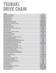
DRIVE CHAINS - Tsubaki
DRIVE CHAINS - Tsubaki
DRIVE CHAINS - Tsubaki

Create successful ePaper yourself
Turn your PDF publications into a flip-book with our unique Google optimized e-Paper software.
Before Use For Safe UseStandard Roller Chains Lube-Free Roller Chains Heavy Duty Roller Chains Corrosion Resistant Roller Chains Specialty Roller Chains Accessories Selection HandlingStep 26. Allowable Load Selection MethodStep 1Calculate from loadCheck the mass M(weight W) of the loadService factor: KsRPM: KnNumber of teeth factor: KzCalculate designchain tension: F’wProceduresConfirm data required for selectionStep 2Check motor characteristicsStart frequencyOver 6 times/day (8h)With cushionedstart and stopCalculate from loadStep 3Calculate fromacceleration/deceleration timeAcceleration time: tsCalculate chaintension: FsRPM: KnDeceleration time: tbCalculate chaintension: FbUse the larger valueNumber of teeth factor: KzCalculate designchain tension: F’s (F’b)Use the larger valueCalculate from inertia ratio RStarting torque: TsCalculate chaintension: FmsDecide the chain size so that the larger of F’w,F’s (F’b) and F’ms (F’mb) maximum allowable tensionDecide small sprocket: Z’, and large sprocket: ZCheck distance between shaftsCheck maximum shaft hole diameterDecide chain and sprocketCalculate chain length (number of links) LDecide on lubrication method from the smallsprocket rotation speed, referring to the kilowattratings table of a chain with identical pitchEndShock factor: KUse the larger valueStep 4Stalling torque: TbCalculate chaintension: FmbCalculate designchain tension: F’ms (Fmb)Selection Speed LimitPitch mmSpeed limitm/minThe following selection methoduses maximum allowable loadfor products with no kilowattratings tables, or for productsoperated under low speeds withfrequent stops.(1)For transmission with large shocksand other extreme conditions, inparticular large-load transmissionand transmission where a thrustload may operate, use F-typeconnecting links or two-pitchoffset links.(2)When using a one-pitch offset link,or a Super Chain 4 pitch offset link,make the following allowances forstrength with respect to themaximum allowable loadM-type CL*: 100%F-type CL: 100%Two-pitch offset link: 100%(Reference)One-pitch offset link: 65%4 pitch offset link: 90%(Super Chain single strand)One and two-pitch offset link: 60%(BS/DIN Chain)(3)There is a possibility that the rimor boss of commercially availablecast iron sprockets are notstrong enough for the hightension of SUPER Chain, SUPER-H Roller Chain, and ULTRASUPER Chain. A type, B type,and C type RS sprockets aresuitably strong.(Use SS400, S35C, SC450, etc.)(4)For high-speed sprockets, use asprocket with hardened toothtips.(5)Be sure to lubricate roller chain,as the bearing pressure risesvery high.* Allow an 80% reductionfor M type connectinglinks for RS15, 25, 37,38, 41, BF25-H, 05B,06B, 48B, 56B andCorrosion Resistant rollerchain RS-KT.141The speed limit for PolySteel Chain is 70 m/min.