DRIVE CHAINS - Tsubaki
DRIVE CHAINS - Tsubaki
DRIVE CHAINS - Tsubaki

Create successful ePaper yourself
Turn your PDF publications into a flip-book with our unique Google optimized e-Paper software.
<strong>Tsubaki</strong>: RecognizedProvider forBasic Environmental Policy of the <strong>Tsubaki</strong> Chain GroupThe <strong>Tsubaki</strong> Chain Group recognizes that theprotection of the global environment is one of the chiefresponsibilities of all mankind. It is our goal to showconsideration for the environment in all of ourbusiness activities in order to contribute to a bettertomorrow.1PhilosophyPolicyAlways be aware of the environmental effects ofbusiness activities, products and services, andstrive to reduce the related environmental load fromthe perspective of global environmental protection.Streamline our organization for environmentalprotection and continually improve our environmentalmanagement systems.Comply with environmental laws, regulations andagreements.Help the entire workforce understand our basicenvironmental policy, and enhance their awarenessof global environmental protection via environmentaleducation, internal publication activities, etc.
T S U B A K I D R I V E C H A I NWorldwide as a SolutionsManufacturing EnvironmentsKyotanabe Plant ConceptsKind consideration towards the global environmentHarmony and coexistence with the global environmentPursuit of high efficiency and high qualityInternationally Accredited Plant<strong>Tsubaki</strong>moto Chain aims to make products that are people-friendly,environmentally friendly, and reliable. The Chain Division acquiredISO9001 accreditation in 1995 and ISO14001 accreditation in2003.Courage to look to the future<strong>Tsubaki</strong>moto Chain’s Kyotanabe Plant is astate-of-the-art facility outfitted with thelatest environmental systems to produceenvironment-friendly products that meetthe needs of the times and our customers.ISO 9001 ISO 14001JQA-0911Chain DivisionJQA-EM3392Kyotanabe PlantKyotanabe Plant2
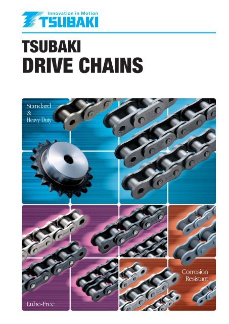
RThe Powerful <strong>Tsubaki</strong> LineBecause it’s <strong>Tsubaki</strong>, customers can select the best products for theirproduction environment from amongst our powerful lineup. Companieslooking to improve their productivity shouldn’t miss trying <strong>Tsubaki</strong>’s drivechains.RS Roller Chain "G7"General PurposeStandard Roller Chains<strong>Tsubaki</strong>’s roller chains greatly improve transmissionpower and deliver performance tailored to size.Lube-FreeLube-Free Drive Chains<strong>Tsubaki</strong>’s lube-free drive chains contribute to lowermaintenance, cleaner work environments, andincreased productivity.* Lambda Chains are also available for conveyor applications.Lambda ChainX-Lambda ChainSurface Treated Lambda ChainHeavy Duty Lambda ChainCurved Lambda ChainBS Lambda ChainRS Roller ChainBS/DIN Standard RS Roller ChainHeavy DutyHeavy Duty Drive Chains<strong>Tsubaki</strong>’s heavy-duty drive chains offer highertransmission capacity and greater allowable loadand tensile strength than RS Roller Chains, thusenabling the use of chains 1 or 2 sizes smaller.Heavy Duty Roller ChainSUPER Roller ChainSUPER-H Roller ChainULTRA SUPER Roller Chain3
T S U B A K I D R I V E C H A I Nfor Boosting ProductivityCorrosion ResistantCorrosion Resistant Drive Chains<strong>Tsubaki</strong>’s corrosion resistant drive chains can beused in a variety of environments.Stainless Steel Drive ChainsSS SpecificationNS SpecificationAS SpecificationSpecialty ChainSpecialty Chains<strong>Tsubaki</strong> also has chains for special applications.Curved Roller ChainCurved Roller ChainStainless Steel Roller ChainSS SpecificationStainless Steel Roller ChainAS SpecificationLeaf ChainLeaf ChainPin Gear Attachment ChainSurface Treated Drive ChainsSurface Treated Drive Chain (NEP)NP SpecificationNEP SpecificationAPP SpecificationTitanium Roller ChainPoly Steel ChainLow Noise Roller ChainCold Resistant Roller ChainAccessoriesChain Elongation ScaleAccessories<strong>Tsubaki</strong>’s chain accessories meet user demands forchain maintenance.Chain TensionerChain Cutting ToolsChain Coupling ToolsEnd FittingsChain Elongation ScalePoly Steel ChainLow Noise Roller Chain4
ContentsBefore UseNotes on Using Roller Chains P7General Comparison of Transmission Elements P8Features and Precautions of P8Roller Chain TransmissionGlossaryRoller Chain ConstructionRoller Chain and SpecialtyChain Line-upSafetyP7P9P11P13P15Ordering RS Roller Chain P16Introduction to RS Roller Chain ’G7’ P19Drive Chain Dimensions / SpecificationsStandard Roller ChainsP19Old-New Chain Number Comparison P21RS Roller Chain P23BS/DIN Standard RS Roller Chain P53P61Lube-Free Roller ChainsOld-New Chain Number Comparison P63Lambda Chain P65Surface Treated Lambda Chain P66X-Lambda Chain P67Lambda Chain KF Series P68Heavy Duty Lambda Chain P71Heavy Duty Lambda Chain NP Specification P72Curved Lambda Chain P73BS Lambda Chain P74Heavy Duty Roller ChainsP77Old-New Chain Number Comparison P79RS-HT Chain P81SUPER Roller Chain P89SUPER-H Roller Chain P96ULTRA SUPER Roller Chain P97Corrosion Resistant Roller ChainsOld-New Chain Number ComparisonP100P102Stainless Steel Roller Chain(SS, NS, AS Specification)Surface Treated Roller Chain P104(NP, NEP, APP Specification)Titanium Roller Chain P107Poly Steel Chain (RS / BS) P107P108Low Noise Roller ChainCold Resistant Roller Chain P112Curved Stainless Steel Roller Chain P112Specialty Roller ChainsP98P113Curved Roller Chain P113Leaf Chain P114Pin Gear Attachment Chain P119RollerCHAIN5
T S U B A K I D R I V E C H A I NAccessories (peripheral instruments) P122Handling Roller Chains and SprocketsP158Old-New Chain Number Comparison P123Chain TensionerP124Chain Cutting Tools P127Chain Connecting Tools P127End FixturesP128Chain Elongation Scale P129Roller Chain SelectionP1301. Selection Guide P1312. Service Factors P1333. Provisional Selection Graph P1344. Selection Formulae P1365. General Selection P1396. Allowable Load Selection P1417. Example of Lifting Transmissions P1468. Calculating Moment of Inertia P1489. Example of Shuttle TractionP14910.Pin Gear Drive Selection P15011.Temperature Selection P15612.Special Selection Method for P156Corrosion-Resistant Roller Chain13.Anti-corrosion Reference Guide for P157Corrosion Resistant Drive Chains and Sprockets1. How to Cut Roller Chain P1582. How to Connect Roller ChainP1593. Roller Chain Lubrication P1604. Layout and Installation P1625. Sprockets P1646. Chain Test Run P1657. Roller Chain Inspection P1658. Cautions on Use in Special Environments P1699. Troubleshooting P170Roller Chain Inquiry SheetP174WARNINGJapan Chain AssociationThe chains, sprockets and other products appearing in this catalog are manufactured with care. However, ifnot properly selected, handled, or maintained, chains may break, resulting in serious accident. Use designmaterials, selection criteria, and instruction manuals as reference for selecting, handling, and maintainingchains and sprockets, and confirm any uncertainties with the manufacturer before proceeding.1.The specifications, dimensions and other particulars specified in this catalog are subject to change for improvement. Before designing your system, please consult with <strong>Tsubaki</strong>moto Chain Co.2. C The contents of this catalog are copyrighted by <strong>Tsubaki</strong>moto Chain Co. with all rights reserved. No part of it may be copied without the written consent of <strong>Tsubaki</strong>moto Chain Co.3.The logos, brand or product names in this catalog are trademarks or registered trademarks of <strong>Tsubaki</strong>moto Chain Co. in Japan and other countries.LINE-UP6
Before UseT S U B A K I D R I V E C H A I NBefore Use For Safe UseStandard Roller Chains Lube-Free Roller Chains Heavy Duty Roller Chains Corrosion Resistant Roller Chains Specialty Roller Chains Accessories Selection HandlingNOTEWith the exception ofendless chains, thetransmission power tablesin this catalog are basedon use with connectingparts (connecting links oroffset links).See page 12 for details onconnecting parts.NOTEThis drive chain catalog explains how to select, install and maintain all listed <strong>Tsubaki</strong> RollerChains. Numerical figures are indicated in both SI and gravimetric units.Read through this catalog before use to ensure proper selection and usage. Also, carefullyinform persons involved in installation and maintenance of all pertinent matters.Ordinary TransmissionShuttle TractionPin Gear DriveNotes on Using Roller ChainsLifting ApplicationsDrumPin gearattachment chainPin gearsprocketWhen using a roller chain in lifting applications, keep clear from underneath the load.If there is the possibility of serious accident or death in the event of roller chainbreakage during lifting or other applications, install reliable safety devices to preventaccidents.Inspect and replace worn roller chain periodically.Roller chains can break and climb up on the sprocket from wear elongation.(Lubrication can extend service life against wear elongation. <strong>Tsubaki</strong> also offers lubefreedrive chains that deliver long-lasting service without lubrication.)Overload may cause roller chain to break. (Avoid breakage by properly selectingproducts with consideration to inertia, etc. <strong>Tsubaki</strong> offers heavy-duty drive chains inidentical sizes that deliver the high strength of larger chains.)Roller chains can break due to corrosion and other environmental conditions. (Avoidbreakage superior by preventing exposure to corrosive liquids, atmospheres, etc.<strong>Tsubaki</strong> offers corrosion-resistant drive chains.)Correctly install roller chain to avoid misalignment or uneven wear and possible breakage.7
T S U B A K I D R I V E C H A I NGeneral Comparison of Transmission ElementsThe following table compares roller chains to other power transmission mechanisms such astoothed belts, V-belts and gears. Generally speaking, roller chains are often used aseconomical power transmission suited to low speed and high loads. However, it is alsopossible to use chain in high-speed applications such as camshaft drives for automobiles.TransmissionMechanismSynchronicityTransmissionEfficiencyAnti-shockNoise & VibrationAmbient ConditionsSpaceWeightHigh speed,light loadLow speed,heavy loadLubricationLayout FreedomExcess Loadon ShaftRoller Chain Avoid water and dust.(Corrosion-resistantdrive chains available.)Compact,lightweightAvoid heat, oil,water and dust.Avoid heat, oil,water and dust. Slightly heavypulleysRequiredExcellentGoodFairPoorFeatures and Precautions of Roller Chain Transmissions1.2.3.4.5.6.7.8.9.1.2.3.4.FeaturesWide with heavypulleysAccommodetes large speed reductions/increases (usually up to 1:7).Chain can accommodate long shaft center distances (normally less than 4 m), and is more versatile.It is possible to use chain with multiple shafts or drives with both sides of the chain.Easy installation and replacement (easy to cut and connect chains).Drive use is possible even when shafts are vertical, as long as the chain receives support in shortdistances between the shafts.Standardization of chains under the American National Standards Institute (ANSI), the InternationalStandardization Organization (ISO), and the Japanese Industrial Standards (JIS) allow ease ofselection.The sprocket diameter for a chain system may be smaller than a belt pulley while transmitting thesame torque.Sprockets are subject to less wear than gears because sprockets distribute the load over their manyteeth.High shock absorbency compared with gears.PrecautionsToothed Belt V-belt GearNot requiredNot required Chain has speed variation, called chordal action, which is caused by the polygonal effect of thesprockets.(Shock can be reduced under the same speed ratio by either reducing the chain pitch orincreasing the number of sprocket teeth.)During transmission, a method of lubrication suitable to the chain’s speed is necessary.Chain wears and elongates. Measures for adjusting chain slack need to be considered.Chain is weak when subjected to loads from the side. It needs proper alignment.Avoid waterand dust.Needs high strengthdue to low numberof engaging teeth.RequiredBefore Use For Safe Use Standard Roller Chains Lube-Free Roller Chains Heavy Duty Roller Chains Corrosion Resistant Roller Chains Specialty Roller Chains Accessories Selection Handling8
GlossaryT S U B A K I D R I V E C H A I NBefore Use For Safe UseStandard Roller Chains Lube-Free Roller Chains Heavy Duty Roller Chains Corrosion Resistant Roller Chains Specialty Roller Chains Accessories Selection Handling1. ANSI Standard Minimum Tensile Strength (Tensile Breakage Strength)2. <strong>Tsubaki</strong> Average Tensile Strength3. <strong>Tsubaki</strong> Minimum Tensile Strength4.Maximum Allowable LoadThis is the minimum tensile strength determined by ANSI Standard. If a roller chain breaksfrom a tensile load below this value, then it is non-compliant. In the case of multi-strand rollerchain, the single strand value is multiplied by the number of strands. (ANSI B 29.100)This is a fracture load reading obtained after a long period of actual tensile strength testing ofa large number of chain strands. Naturally, a roller chain may actually break at a higher orlower value than this, so it does not represent a guaranteed value. This value variesdepending on the manufacturer.This is a minimum value determined bystatistical processing at <strong>Tsubaki</strong>. If anyroller chain fractures by a tensile loadbelow this value, then it is noncompliant.This value varies dependingon the manufacturer.Testing MethodAs shown in Fig. 2, roller chain with over five links is fixed at both ends by clevises and isstretched until breakage occurs (JIS B 1801-2009). The type of fracture is indicated bybreakage of the roller chain or failure of its parts (Fig. 3.)Fig. 2 Tensile strength testThe maximum allowable load of roller chain (excluding Stainless Steel Chain and EngineeringPlastic Chain*) is the value derived from the lowest fatigue limit. When a load lower than thisvalue is repetitively applied to the roller chain, fatigue failure will never occur.According to the former JIS B 1801-1997, the maximum allowable load indicates abreakage load of Pmax = (Pm + Pa) = 2.2Pa at a frequency of 5 10 6 , when a newroller chain with over five links receives a repetitive load in linear operation. (Fig. 4)<strong>Tsubaki</strong> standards and catalog values are for 10 7 repetitions, or 2Pa. In other words, if<strong>Tsubaki</strong>’s maximum allowable load is indicated as maximum load (Pmax), then values in thiscatalog would increase 10%.Fig. 4 Summary chart of repetitive loadLoadFig. 1 Relationship between three tensile strengthsJIS minimum tensile strength<strong>Tsubaki</strong> minimum tensile strengthFrequencyFig. 3 Shape of fractureAverage tensile strengthTensile strength* Stainless steel and engineered plastic chains:Maximum allowable load is determined from specifying the surfacepressure between pins and bushes based on wear performance.Note that strength of offset links may belower than the chain itself.(Refer to each product page for details.)Time9
T S U B A K I D R I V E C H A I N5. Kilowatt Ratings Table6. Moment of Inertia (I / J / GD 2 )7. Total Length Tolerance of Roller Chain8. Elastic Elongation of Chain under LoadRS Roller Chain, SUPER Roller Chain, Heavy Duty Chain, and Low Noise Drive Chainkilowatt ratings tables show kW values for 15,000 hours of operation using a two-shaft driveand 100 pitches of roller chain under conditions 1 - 5 below.The kW ratings table of Lambda Chain is based on conditions 1 - 4 and shows kW ratingvalues when Lambda Chain is used with two shafts. Lambda Chain has more than seventimes the wear elongation of Standard RS Roller Chain operated without lubrication (#120 and#140 are over 2.5 times). X-LAMBDA has more than five times the wear elongation life ofLambda Roller Chain.1) The chains are operated under ordinary conditions where the ambient temperature is -10 - +60(+14F - +140F) and there is no abrasive dust.2) There are no negative effects from corrosive gasses or high humidity.3) The two shafts are level and the chains are properly installed. (See item 4 on pg. 162.)4) There is minimal fluctuation in load during transmission.5) The recommended lubrication system and lubricant shown in the kW ratings tables is used for RS RollerChain and SUPER Roller Chain. (See pgs. 160 - 161.)Moment of inertia is used to show the degree of inertia in rotational movement; in other words,"rotation difficulty", or "rotation ease." This is equivalent to the mass (weight) of the objectbeing used for straight-line transmission.Moment of inertia is shown in the SI units table as:I = mk 2 (kgm 2 m: mass of rotating body k: turning radius)It is shown in the Gravimetric units table as:J = GK 2(kgfms 2 G: mass of rotating body G: gravitational acceleration).GAlthough, GD 2 = 4GJ (D: diameter of rotating body) is generally being used now in place ofmoment of inertia.Length test method and length tolerance are specified in JIS B 1801-2009. The lengthtolerance of any individual size when subjected to a measured load (e.g. 500 N [50.99 kgf] forRS 80) specified in JIS is 0 to +0.15% of the reference length. The reference length iscalculated by multiplying the reference pitch (P) by the number of links. (Applicable toproducts bearing a JIS identification number.)An elastic elongation curve of a chain under load looks as shown below. Values shown hereare the standard references for single-strand RS Roller Chains. Actual values may slightlydiffer. Do not apply loads greater than the maximum allowable load to roller chains.Load: Maximum allowable loadLoad: Maximum allowable loadBefore Use For Safe Use Standard Roller Chains Lube-Free Roller Chains Heavy Duty Roller Chains Corrosion Resistant Roller Chains Specialty Roller Chains Accessories Selection HandlingElongation of 1 m chain (mm)Elongation of 1 m chain (mm)10
T S U B A K I D R I V E C H A I NRoller Chain ConstructionBefore Use For Safe UseStandard Roller Chains Lube-Free Roller Chains Heavy Duty Roller Chains Corrosion Resistant Roller Chains Specialty Roller Chains Accessories Selection Handling1. Basic Structure (Photo: RS Roller Chain)Offset pinBasic Three DimensionsThe pitch, roller diameter, andinner width of the inner linkare considered the basic threedimensions of a roller chain.When these dimensions areidentical, a roller chain andsprocket are dimensionallycompatible.Cotter pinSpring clips, cotter pins andspring pins are essential partsthat prevent connecting platesfrom falling off, maintainingthe strength of the chain itself.Always install these parts.*Slip FitWhen the shafts and holes arefitted together, there is acontinuous loose fit. This is afit where the range of tolerancefor the hole is larger than therange of tolerance for the shaft(pin or bush).*Press FitWhen the shafts and holes arefitted together, there is acontinuous interferential fit. Thisis a fit where the range oftolerance for the hole is smallerthan the range of tolerance forthe shaft (pin or bush).Slip fitPlateOuter linkRollerdiameterOffset linkInner linkPitchConnecting linkChainWidth between inner link platesThe plate bears the tension placed on the chain. Usually this is a repetitive load, butsometimes it is accompanied by shock. Therefore, the plate must have not only great statictensile strength, but also must hold up to the dynamic forces of load and shock.PinPress fitPress fit*2Press fitSlip fit*1The pin is subject to shearing and bending forces transmitted by the plate. At the same time, itforms a load-bearing part, together with the bush, when the chain flexes during sprocketengagement. Therefore, the pin needs high tensile and shear strength, resistance to bending,and sufficient endurance against shock and wear.BushPinRollerBushConnecting link plateSpring clipInner linkInner plateOuter plateMiddle plateSingle-strandouter linkMulti-strand outer link(Double-strand shown here)chainThe bush is subject to complex forces from all parts, especially from the repetition of shockloads when the chain engages the sprocket. Therefore, the bush needs extremely high shockresistance. In addition, the bush forms a load-bearing part together with the pin, and as suchrequires great wear resistance.RollerThe roller is subject to impact load as it strikes the sprocket teeth during chain engagementwith the sprocket. After engagement, the roller changes its point of contact and balance. It isheld between the sprocket teeth and bush, and moves on the tooth face while receiving acompression load. Therefore, it must be resistant to wear and still have strength againstshock, fatigue and compression. RS11 / 15 / 25 / 35 do not have rollers.Roller LinkTwo bushes are press fit into two inner plates, and rollers are inserted to allow rotation aroundthe outside of the bush. This is the same for single-strand and multi-strand chain.Outer Link and Middle PlateThe pin link consists of two pins that have been press fit into two outer plates. With multistrandroller chain, a middle plate is added to the pin link. The middle plate is slip fit forStandard RS Roller Chain and press fit for SUPER Roller Chain.11
T S U B A K I D R I V E C H A I N2. Assembly PartsRoller Chains are usually made up of a number of connected links in an endless formation, or used by fixing the chain ends, butthe need for connecting links will eventually arise. Although offset links can be used when there are an odd number of links inthe roller chain, please use a design that requires an even number of links as much as possible.2.1 Connecting LinksM-type Connecting linkClip typeOuter plateConnecting link plate(RC-processing)Cotter pin typeCotter pin typeMulti-strand (Double-strand shown)Outer plateConnecting link plate(RC-processing)Spring pin type(RS240 only)Connecting link plate(RC-processing)F-type Connecting linkPin Pin Middle platePin Pin PinClipCotter pin1-Pitch Offset Link (OL)Single-strandOffset link plateMulti-strand(double-strand shown)Cotter pinSpring pin2-Pitch Offset LinkSingle-strandMulti-strand(double-strand shown)Offset link plateSpring clipOuter platePin / Connecting ConnectingChain type Connecting link type Notelink plate fitting link plate fasteningRS Roller ChainLambda ChainSUPERRoller ChainSUPER-HRoller ChainHeavy DutyRoller ChainOther rollerchains in catalog2.2 Offset Link1-Pitch Offset LinkFor RS35 to RS60 offset links, allow for a20% reduction in kW (35% less for RS80 toRS240) and 35% less maximum allowableload (same for RS80 to RS240).M-type connecting linkCode: CLF-type connecting link *Code: FCLM-type connecting linkCode: CLM-type connecting linkCode: MCLF-type connecting linkCode: FCLF-type connecting linkCode: CLF-type connecting linkCode: CL M-type connecting linkCode: CL2-Pitch Offset LinksThe pin and offset link plate of a 2POL is pressfit and is fastened by a rivet. They can be usedin accordance with the kW ratings tables.4-Pitch Offset Link4POL can be used with (single-strand) SUPERRoller Chains. Allow for a 10% reduction inmaximum allowable load and kW ratings.Slip fit(M)Press fitSlip fit(M)Slip fit(M)Press fitPress fitPress fitSlip fit(M)PinSpring clipCotter pinSpring pinSpring clip, Cotter pinSpring pinT-pinSpring clipCotter pinSpring pinSpring pinSpring pinCotter pinSpring pinCotter pin, Spring clipSpring pinT-pin, Z-pinPinConnecting link plateSingle-strandCotter pinFor multi-strand chain, make sure the platewith *RC processing is on the outermost sidewhen assembling.Operating speed is indicated by the white areain the kW ratings table.Make sure to use the chain according to the specifiedapplications on page 131 and within the speed regionof the colored area in the kW rating tables.Can be used in all areas of the kW ratingstable for Lambda Chain.Connecting plates are RC-processed.Connecting plates are RC-processed.Use under extreme conditions (e.g., high shock,very high load, possible side force, etc.).Use exclusive connecting link.Use exclusive connecting link.Refer to individual dimension diagrams.Only NP, NEP and Low Noise Roller Chainsuse RC-processed connecting link plates.Note 1. The connecting link plate fastening method for each chain size is indicated in the dimension tables and the table notes.2. The color of F-type connecting links for RS Roller Chain and RS-HT Roller Chain marked with * is black.Remark: Ring Coin (RC) ProcessingThis <strong>Tsubaki</strong> original processing adds an area of plastic deformation around pin holes to generate residual stress around the holes.4-Pitch Offset LinkNote: See the dimensional tables for roller chain types and sizes suitable for offset links.Before Use For Safe Use Standard Roller Chains Lube-Free Roller Chains Heavy Duty Roller Chains Corrosion Resistant Roller Chains Specialty Roller Chains Accessories Selection Handling See the notes for BS/DIN Standard RS Roller Chains section.12
T S U B A K I D R I V E C H A I NRoller Chain and Specialty Chain LineupBefore Use For Safe UseStandard Roller Chains Lube-Free Roller Chains Heavy Duty Roller Chains Corrosion Resistant Roller Chains Specialty Roller Chains Accessories Selection HandlingSeriesStandardRoller ChainsLube-FreeRoller ChainsHeavy DutyRoller ChainsCorrosionResistantRoller ChainsSpecialtyRoller ChainsProductRS Roller ChainBS/DIN StandardRS Roller ChainLambda ChainSurface TreatedLambda ChainX-Lambda ChainLambda ChainKF SeriesHeavy DutyLambda ChainCurvedLambda ChainBSLambda ChainHeavy DutyRoller ChainSUPERRoller ChainSUPER-HRoller ChainULTRA SUPERRoller ChainStainless SteelRoller ChainSurface TreatedRoller ChainFeatures/ApplicationsJIS-, ISO-compliantISO-compliant seriesLube-free, long-life (Special oil-impregnated bush)Lube-free, long-life (Special oil-impregnated bush)Surface treated (NP and NEP)Operatingtemperaturerange ()—10 to + 60 *1—10 to +150—10 to +230—10 to +150Titanium Roller Chain Made of nonmagnetic titanium, high corrosion resistance —10 to +60Cold Resistant Roller Chain Cold resistance specification —40 to +60Low Noise Roller Chain Spring rollers, low noise —10 to +60Poly Steel Chain Corrosion resistance, wear resistance, low noise, lightweight —10 to +80Curved Roller Chain Side-flexing chain, curved transmissions —10 to +60Curved Stainless Steel Stainless steel, curved transmissionsRoller ChainLeaf ChainPin Gear Attachment ChainSuper long-life via special oil-impregnatedbush and felt sealLube-free, long-life (Special oil-impregnated bush), forhigh temperatures and food processing equipment.Lube-free, long-life (Special oil-impregnated bush),heavy-duty, double-strand onlyLube-free, long-life (Special oil-impregnated bush),for curved linesLube-free, long-life (Special oil-impregnated bush),ISO-compliant BS SeriesHigh tensile strength(Approx. 19% increase over RS)High tensile strength(Approx. 30% increase over RS)High fatigue strength, high tensile strength,for heavy-duty transmissionsMaximum fatigue strength, maximum tensilestrength, for super heavy-duty transmissionsSSNSASNPNEPAPPHigh corrosion resistance, high heat resistanceHigher corrosion resistance and higher heatresistance than SS1.5x maximum allowable load of SS, slightlyless corrosion resistanceLow corrosion resistance, special nickel platingHigh corrosion resistanceAnti-pittingPlate and pin construction, for lifting applications,AL-type, BL-type (AL ), (BL )Used in anchored configuration, gear transmission—10 to +60—20 to +400—10 to +60—20 to +400—10 to +6013
SizesT S U B A K I D R I V E C H A I N111525354050Chain No. (Pitch: mm) *260803.7465 4.7625 6.359.52512.70 15.875 19.05 25.40 31.75 38.10 44.45 50.80 57.15 63.50 76.20 100RF06B RS08B RS10B RS12B RS16B RS20B RS24B RS28B RS32B RS40B RS48B*3 *3 120 140160 180200240 RF06B RS08B RS10B RS12B RS16B RS20B RS24B RS28B RS32B RS40B 4 5 6 8 10 12 14 16Ref. page21617798113Before Use For Safe Use Standard Roller Chains Lube-Free Roller Chains Heavy Duty Roller Chains Corrosion Resistant Roller Chains Specialty Roller Chains Accessories Selection Handling*1: The operating temperature range of pre-lubricated chains (those coated with oil when delivered) is -10 to +60 (-40 to +60 for KT specification).Chain kW ratings do not decrease until 150. To use in +60 to 150environments, apply a high temperature lubrication. For details and precautions inusage, see "Temperature Selection Method" (page 156) and "Roller Chain Lubrication" (page 160).*2: Sizes marked with are standard products shown in this catalog. For details, see the corresponding section. Blank cells are specialty items and may bespecially ordered. Contact <strong>Tsubaki</strong> for details.*3: RS05B (pitch 8.00) and RS56B (pitch 88.9) are also available.14
Before Use For Safe UseStandard Roller Chains Lube-Free Roller Chains Heavy Duty Roller Chains Corrosion Resistant Roller Chains Specialty Roller Chains Accessories Selection HandlingFor Safe UseWARNING Obey the following points in order to prevent hazardous situations.Do not use chains and accessories (accessories and parts) for anything other than their original purpose.Never perform additional processing on the chain.. Do not anneal the various parts of the chain.. Do not clean the chain with either acid or alkali, as they may cause cracking.. Do not electroplate the chain or its parts, as it may cause cracking due to hydrogen embrittlement.. Do not weld the chain, as the heat may cause cracking or a reduction in strength.. When heating or cutting the chain with a torch, remove the links immediately adjacent and do not use them again.When there is need to replace a lost or damaged portion of a chain, always replace the whole chain witha new product rather than replacing only the lost or damaged portion.When using a chain on suspension equipment, establish a safety perimeter and strictly prevent entry tothe area directly below the suspended object.Always employ hazard protection devices for the chain and sprocket (safety cover, etc.).If a substance that can cause embrittlement cracking (acid, strong alkali, battery fluid, etc.) adheres to thechain, stop using the chain immediately and replace it with a new one.During installation, removal, maintenance inspection and lubrication of the chain:. Perform the operation according to the instruction manual or this catalog.. Always turn off the power switch to the device and make sure that it cannot be turned on accidentally.. Anchor the chain and parts so that they cannot move freely.. Perform cutting and connecting procedures properly using a press or other special tool.. Wear clothing and employ protective devices that are appropriate to the job (safety glasses, gloves, safety shoes, etc.).. Only allow experienced personnel to perform chain replacement procedures.A fail safe back up system is suggested whenever using Leaf Chain to safely support the load in the eventof a chain failure.CAUTIONObey the following points in order to prevent accidents.Only handle the chain after thoroughly understanding its structure and specifications.When installing a chain, inspect it in advance to confirm that it has not been damaged in transport.Be sure to perform regular maintenance inspections on the chain and sprocket.Chain strength varies according to manufacturer. When selecting a chain based on a <strong>Tsubaki</strong> catalog,always use the corresponding <strong>Tsubaki</strong> product.Minimum tensile strength refers to the failure point when the corresponding load is applied to the chain onceand does not refer to the allowable operational load.Warranty1. LIMITED WARRANTYProducts manufactured by Seller: (a) conform to the design andspecifications, if any, expressly agreed to in writing by Seller; and(b) are free of defects in workmanship and materials at the timeof shipment. The warranties set forth in the preceding sentenceare exclusive of all other warranties, express or implied, andextend only to Buyer and to no other person. ALL WARRANTIESOF MERCHANTABILITY OR FITNESS FOR A PARTICULARPURPOSE ARE HEREBY EXCLUDED.2. NON-RELIANCEBuyer is not relying upon any advice, representations orwarranties (except the warranties expressly set forth above) ofSeller, or upon Seller's skill or judgment regarding the Seller'sproducts.Buyer is solely responsible for the design and specifications ofthe products, including without limitation, the determination ofsuitability for Buyer's application of the products.3. CLAIMS(a) Any claim relating to quantity or type shall be made to Seller inwriting within 7 days after receipt of the products; any suchclaim made thereafter shall be barred.(b) Any claim under the above-stated Limited Warranty shall bemade to Seller in writing within three (3) months after receipt ofthe products; any such claim made thereafter shall be barred.(c) Seller's liability for breach of warranty or otherwise is limited torepair or replacement, at Seller's option, of non-conforming ordefective products. Buyer waives all other remedies, including,but not limited to, all rights to consequential, special orincidental damages, including, but not limited to, damagesresulting from personal injury, death or damage to or loss ofuse of property.(d) Repair, alteration, neglect or misuse of the products shall voidall applicable warranties.4. INDEMNIFICATIONBuyer will indemnify, defend and hold Seller harmless from allloss, liability, damage and expense, including attorneys' fees,arising out of any claim (a) for infringement of any patent,trademark, copyright, misappropriation of trade secrets, unfaircompetition or similar charge by any products supplied by Sellerin accordance with the design or specifications furnished byBuyer, or (b) arising out of or connected with the products or anyitems into which the products are incorporated, including, but notlimited to, any claim for product liability (whether or not based onnegligence or strict liability of Seller), breach of warranty, breachof contract or otherwise.5. ENTIRE AGREEMENTThese terms and conditions constitute the entire agreementbetween Buyer and Seller and supersede any inconsistent termsand conditions, whether contained in Buyer's purchase order orotherwise, and whether made heretofore or hereafter.No statement or writing subsequent to the date hereof whichpurports to modify or add to the terms and conditions hereof shallbe binding unless consented to in writing, which makes specificreference hereto, and which has been signed by the partyagainst which enforcement thereof is sought. Seller reserves theright to change these terms and conditions without prior notice.15
Ordering RS Roller ChainT S U B A K I D R I V E C H A I NBefore Use For Safe UseStandard Roller Chains Lube-Free Roller Chains Heavy Duty Roller Chains Corrosion Resistant Roller Chains Specialty Roller Chains Accessories Selection Handling3. Ordering an odd number of linksBe sure to indicate "configuration specification". If no specification is made for an oddnumber of links, both end links will be inner links (both RL) as in [4].1 9 links (including CL and OL)2 9 links (specified to include 2POL)3 9 links (both ends with CL)4 9 links (both ends inner links)5 9 links (both ends outer links)After installing the equipment, use a riveting punch (see theaccessories section) to fasten the pin ends of the rivets inthe outer links on both ends.Product codeA110018 RS50-1-RP 7A115018 RS50-1-CL 1A116013 RS50-1-OL 1Configuration specificationProduct codeA110018 RS50-1-RP 5A115018 RS50-1-CL 2A116080 RS50-1-2POL 1Configuration specification9LX1H CL,OLLKK9LX1H2POL,CLNote: To specify that parts be installed, an assembly specificationsuch as CL - OL (2POL) is required.Product codeChainnumberCountA110018 RS50-1-RP 7A115018 RS50-1-CL 2Configuration specificationProduct codeChainnumberChainnumberCountCountUnits9LX1H CL-CLNote: To specify that parts be installed, an assembly specificationsuch as CL - OL (2POL) is required.A110018 RS50-1-RP 9 LConfiguration specificationProduct codeChainnumberChainnumberCountLKKUnitsUnitsLKUnits9LX1HRL-RLCountUnitsA110018 RS50-1-RP 9 LConfiguration specificationNote: To specify that parts be installed, an assembly specificationsuch as CL - OL (2POL) is required.9LX1HPL-PLThe photograph in each example order shows CL and OL assembled. In an actual order, CL and OL aredelivered unassembled. If you wish parts to be assembled, a configuration specification is necessary.17
T S U B A K I D R I V E C H A I N4. Matched and tagged chainDeviations in chain length exist due to the manufacturingtolerances of the parts. When chains are to be used in paralleland minimizing the relative difference in the lengths is necessary,request a "matched and tagged" chain.Note: A separate charge is required for a length matching.5. Long length formation6. Reel chainSingle-strand RS25 to RS80 chain (see table below) is available on long-length reels.7. Replacement precautionsWhen you do not know the roller chain numberFor example, if you need three sets of two single-strand,120-link RS80 chains, the entry should be:When a chain s total length exceeds 3.048m (10ft), it is called a long length formation. Please consult a <strong>Tsubaki</strong> representativefor information regarding chains exceeding the lengths below. A separate super long length formation fee and wooden box feeapplies.Example orderOrdering one reel of RS50-1-RP Roller ChainProduct codeChainnumberCount UnitsA110089 RS50-1-RP-10UR 1 RProduct codeA110083A110084A110085A110086A110087A110088A110089A110090A110091Chain number Units per reel Number of links (unit: L)Number of accessory CL(M-type connecting links)RS25-1-RP-150UR 15023999 150RS35-1-RP-20UR 206399 20RS37-1-RP-20UR 20479920RS38-1-RP-20UR 20479920RS41-1-RP-20UR 20479920RS40-1-RP-15UR 15359915RS50-1-RP-10UR 10191910RS60-1-RP-10UR 10159910RS80-1-RP-5UR 559951 2 3Verification of theroller chain specifications(strength type, material, etc.)is important. Check with themanufacturer.Check the roller chainsize and specifications thatare engraved on the rollerchain plate.Example entry in special mention columnRS80-1-RP 720 linksMatched and tagged chain: 120 L x 2 H x 3 DMeasure the pitch,roller diameter, inner widthof inner link, and platethickness of the roller chain.Before Use For Safe Use Standard Roller Chains Lube-Free Roller Chains Heavy Duty Roller Chains Corrosion Resistant Roller Chains Specialty Roller Chains Accessories Selection Handling18
groovebushesTwo timesthe wear lifeing oil between the pin and bush longer than theWith G7, our newly-developed LG solid bushwith seamless bush for lastingFour times betterthe wear lifeLG Solid BushIncreasesuperior
"World’s No. 1"kilowatt ratings by 25%."World’s No.1kW ratingsgroove, the connecting link achieves the same strength as thechain itself.
Before Use For Safe UseStandard Roller Chains Lube-Free Roller Chains Heavy Duty Roller Chains Corrosion Resistant Roller Chains Specialty Roller Chains Accessories Selection HandlingStandard Roller Chains Old-New Chain Number ComparisonProduct codes have been assigned to all products (except customized products) and chain numbers have been rewritten.The following clarifies the differences between old and new chain numbers.RS Roller ChainOld chain numbers for single-strand chains indicated size only. Add "-1" to all new chain numbers.Double-and higher multi-strand chains will still use the current numbering.RP and CP type needs to be stated with new chain numbers.RPA chain that uses rivets to connect RL and RL with PL.RS80 -1 -RP -UApplicable sizesChain number with connecting link (CL)Chain number with OL/2POLRS11-SS-1RF320-T-1RF400-T-1New chain number15, 25, 37, 38, 41, 40, 50,60, 80, 100, 120, 140,160, 180, 200, 240BF25-H-1-RP-UBF25-H-1-RPor CPRequired for standardstocked products (units).Not required for linksonly.Note: RS11SS, RF320T and RF400T numbers are as follows.New chain numberNote: BF25H numbers are as follows.New chain numberRS80Applicable sizes15, 25, 37, 38, 41, 40, 50, 60,80, 100, 120, 140, 160, 180,200, 240RS80-1-CLFor FCL: RS80-1-FCLRS80-1-OL, RS80-1-2POLOld chain numberRS11SSRF320TRF400TOld chain numberBF25HCPA chain that uses cotter pins to connect RL and RL with PL.Old chain number21
Standard Roller ChainsOld-New Chain Number ComparisonBS Roller Chain (ISO606-compliant B Series)RF06B-1New chain numberRS 08B -1RS Roller ChainOld chain numbers for single-strand chains indicated size only. Add "-1" to all new chain numbers.For double and higher multi-strand chains, confirm size and then simply change the strand listing.Chain number with connecting link (CL)Chain number with OL/2POLApplicable sizes08B, 10B, 12B, 16B, 20B,24B, 28B, 32B, 40BRF06BRS08BRS08B-1-CLRS08B-1-OL, RS08B-1-2POLOld chain numberApplicable sizes08B, 10B, 12B, 16B, 20B,24B, 28B, 32B, 40BBefore Use For Safe Use Standard Roller Chains Lube-Free Roller Chains Heavy Duty Roller Chains Corrosion Resistant Roller Chains Specialty Roller Chains Accessories Selection Handling22
Standard Roller Chains RS Roller ChainRS11-SS-1Before Use For Safe UseStandard Roller Chains Lube-Free Roller Chains Heavy Duty Roller Chains Corrosion Resistant Roller Chains Specialty Roller Chains Accessories Selection HandlingTSUBAKIChain Number3.345 2.2750.383.5RS11-SS-1 780{80} 50{5} 52 134Standard Roller ChainsRS11SS SprocketSprocket NumberTypeChain numberAverageTensile StrengthN{kf}Stainless steelNumber of teeth1.57MaximumAllowable LoadN{kf}Note: 1. Made of SUS 304 stainless steel. 2. No offset links available.3. Bushed chain.3.7465 3.7465Non-stepped teeth1B typeNumber ofteethTypeApproximateMass/mPitch circulardiameter(DP )Stepped teethSprocket outerdiameter(DO)2.285Non-stepped teeth 1C type12 14.475 16.26 9.415 18.020 19.9 9 13416 B or C 19.204 21.1 9 14M30.518 (non-stepped 21.575 23.5 11 1620teeth)23.949 25.924 28.703 30.7 6 13 19 M40.728 33.462 35.530 35.842 37.934 B or C 40.604 42.736 (stepped 42.986 45.1 6 13 19 M40.740 teeth) 47.751 49.848 57.283 59.40.381.83Drawing Scale 2/1Number ofLinks Per UnitBore diameter (d )Min.Max.Hub Set screwdiameter hole(DH )Stepped teethApprox. weight ()1B type 1C type5.9 7.411.5 14.713.5 17.317.7 22.823.3 30.325.7 32.728.7 35.729.7 39.337.9 48.940.7 52.446.5 59.960.5 77.8MaterialStainlesssteelStainlesssteelNote: 1. Bore diameter is customizable within the above ranges. However, the finishing hole tolerance is H8 fordiameters of less than 8 and H7 for diameters of 8 and above.2. Unless bore diameter is specified, sprockets are made to the above minimum size with an H10 tolerance.23
Standard Roller ChainsRS25, BF25-H Sprocket HLRS37-1RS38-1RS41-191011121314151617181920212223242526283032354045d10 20.55 23.5 6H8 8H8 13 14 4 M3X6 1311 22.54 25.5 6H8 8H8 15 14 4 M3X8 1612 24.53 27.5 8H8 10H8 17 14 4 M4X8 2013 26.53 29.5 8H8 10H8 18 14 4 M4X8 2314 28.54 31.5 8H8 10H8 19 14 4 M4X8 2615 30.54 33.5 8H8 10H8 20 14 4 M4X10 3116 32.55 35.5 8H8 10H8 21 16 5 M4X10 3817 34.56 37.5 8H8 10H8 23 16 5 M4X10 4518 36.57 39.5 8H8 10H8 25 16 5 M4X12 5219 38.58 41.5 8H8 10H8 26 16 5 M4X12 6020 40.59 43.5 8H8 10H8 28 16 5 M4X14 6821 42.61 45.5 8H8 10H8 30 18 7 M4X14 8022 44.62 48.0 8H8 10H8 30 18 7 M4X14 8423 46.63 50.0 8H8 10H8 30 18 7 M4X14 8824 48.65 52.0 8H8 10H8 30 18 7 M4X14 9325 50.66 54.0 8H8 10H8 30 18 7 M4X14 9826 52.68 56.0 10H8 12H8 30 18 7 M4X14 9828 56.71 60.0 10H8 12H8 30 18 7 M4X14 10330 60.75 64.0 10H8 12H8 30 18 7 M4X14 11032 64.78 68.0 10H8 12H8 30 18 7 M4X14 117T1 T2 T3 D L1+L2 L1 L2 LRS37-1 12.70 7.80 3.40 1.0 1.0 1.2 3.63 11.0 5.1 5.9 12.45RS38-1 12.70 7.80 4.80 1.1 1.1 1.2 3.63 13.1 6.0 7.1 14.1RS41-1 12.70 7.77 6.38 1.251.251.253.59 14.7 6.757.9515.1RS37-1 8.14{ 830} 9.41{ 960} 1.67{170} 0.29 240RS38-1 8.14{ 830} 9.41{ 960} 1.67{170} 0.35 240RS41-1 7.4{755} 10.3{1050} 11.8{1200} 2.26{230} 0.41 24010 25 50 100 200 300 400 500 700 900 1000 1200 1400 1600 1800 2100 2400 2700 3000 3500 4000 5000 6000 7000 80000.020.030.030.030.030.040.040.040.050.050.050.050.060.060.060.070.070.070.080.080.090.100.120.13SD HD PD OSintered alloy specification (1B type)Sprocket NumberL1Small SprocketNo. of TeethChain numberL2T1T3DType0.050.060.070.070.080.080.090.100.100.110.120.120.130.140.140.150.160.170.180.190.210.230.260.30Notes:1. Bores are finishedand fittedwith a screw.0.100.110.120.140.150.160.170.180.190.210.220.230.240.260.270.280.300.310.330.360.380.430.490.560.180.200.230.250.270.290.320.340.360.390.410.430.460.480.500.530.550.570.620.670.720.790.921.04Bore diameter (d)Number of teethA B C0.340.380.430.470.510.550.590.630.680.720.760.810.850.890.940.981.031.071.161.251.341.481.711.94R0.490.550.610.670.730.790.850.910.981.041.101.161.231.291.351.421.481.541.671.801.932.132.462.792TW0.640.710.790.870.951.021.101.181.261.341.421.511.591.661.751.831.922.002.172.332.512.763.183.62Number ofTeethL0.780.870.971.061.161.251.351.451.551.641.741.841.942.042.142.242.342.452.652.853.063.373.894.42Pitch CircularDiameter(DP )Standard Roller Chains RS Roller Chain1.051.181.311.441.571.701.831.962.092.222.362.492.632.762.903.043.173.313.593.864.144.565.275.991.321.481.641.801.962.132.292.462.622.792.963.133.293.463.633.813.984.154.504.845.195.726.617.50Sprocket OuterDiameter(DO)RS41-1 Maximum Kilowatt Ratings Table (kW Ratings for Single Strand Chain)Lubrication Type1.251.471.691.932.162.342.522.702.883.073.253.443.623.814.004.184.374.564.945.325.716.297.268.250.951.111.281.451.641.842.042.252.452.682.903.163.403.643.894.154.414.685.235.806.397.318.569.72Cross-recessed HeadBore Diameter (d ) HubMachine ScrewDiameter Length Position1 type 2 typeS(DH) (L )(H )TSUBAKIChain NumberTSUBAKIChain Number0.750.881.011.161.311.451.621.781.952.132.312.482.682.873.073.273.483.694.124.575.045.767.048.430.610.720.830.951.071.191.321.451.601.741.892.042.192.352.512.682.843.023.373.744.124.725.766.87PitchPSmall Sprocket Max r/min0.510.600.690.790.901.001.111.221.331.451.581.711.831.972.102.252.392.532.833.133.453.954.835.76Roller Inner Width ofDiameter Inner LinkR W0.410.480.550.630.710.790.880.971.061.161.251.351.451.561.671.781.902.012.252.482.743.133.834.570.340.400.460.510.580.650.720.790.870.951.031.111.191.281.371.451.551.641.842.042.252.573.133.740.280.330.380.430.480.540.600.660.730.790.860.931.001.071.151.221.301.381.541.711.882.152.633.130.240.280.320.370.420.460.510.570.620.680.730.790.850.920.981.041.111.181.311.451.601.842.252.68PlatesANSI Standard <strong>Tsubaki</strong> Minimum <strong>Tsubaki</strong> AverageMin. Tensile Strength Tensile Strength Tensile StrengthkN{kf} kN{kf} kN{kf}0.190.220.250.290.330.370.410.450.490.540.580.630.680.720.780.830.880.931.041.161.281.451.782.13MaximumAllowable LoadkN{kf}0.160.180.210.240.270.300.340.370.400.440.480.510.550.600.630.680.720.760.850.951.041.191.451.740.110.130.150.170.190.220.240.260.290.310.340.370.400.430.460.480.510.540.610.680.750.851.040Approx.Mass()PinsApproximateMassk/m0.080.100.110.130.150.160.180.200.220.240.260.280.300.320.340.370.400.420.460.510000.070.080.090.100.120.130.140.160.170.190.210.220.240.250.28Material0.290000Sintered alloyMachine-structuralcarbon steelNumber of LinksPer UnitNote: 1. Maximum allowable load when using a one-pitch offset link (OL) is 65% of the above.2. Number of links per unit = 2400.050.060.070.080.100.100.120.130.140000000Before Use For Safe Use Standard Roller Chains Lube-Free Roller Chains Heavy Duty Roller Chains Corrosion Resistant Roller Chains Specialty Roller Chains Accessories Selection HandlingNote: 1. Please consult TSUBAKI prior to use of kW ratings in the colored area of the table.LubricationmethodABCManual lubrication or drip lubricationOil bath or slinger disc lubricationForced pump lubricationDetailsonPg. 16126
Standard Roller Chains RS Roller ChainRS35Before Use For Safe UseStandard Roller Chains Lube-Free Roller Chains Heavy Duty Roller Chains Corrosion Resistant Roller Chains Specialty Roller Chains Accessories Selection HandlingL11LSmall SprocketNo. of TeethL1L2RS35-1 1 12.7 5.85 6.85 13.58.7 {887} 9.81{1000} 11.3{1150} 2.16{220} 0.33RS35-2 2 22.8 10.9 11.9 24.5 10.1 Riveting 17.4{1774} 19.6{2000} 22.6{2300} 3.63{370} 0.69RS35-3 3 32.9 16.0 16.9 34.6 26.1{2661} 29.4{3000} 33.8{3450} 5.39{550} 1.05910111213141516171819202122232425262830323540451.257.83.5950 100 300 500 700 900 1200 1500 1800 2100 2500 3000 3500 4000 4500 5000 5500 6000 6500 7000 7500 8000 8500 9000 100000.090.100.120.130.140.150.160.170.190.200.210.220.230.240.260.270.280.290.320.340.370.400.470.530.170.190.220.240.260.280.300.320.350.370.390.410.430.460.480.500.520.550.590.640.680.750.870.99Single strand9.525 9.5250.470.520.580.640.700.750.810.870.930.991.051.111.171.231.291.351.411.471.591.721.842.032.342.66A B C0.740.830.921.011.101.191.281.381.471.561.661.751.851.942.042.132.232.332.522.722.913.213.714.21L1.001.121.241.371.491.611.741.861.992.122.252.372.502.632.762.893.023.153.413.683.944.345.025.701.261.411.561.711.872.022.182.342.502.662.812.983.143.303.463.623.793.954.284.614.945.456.297.141.631.822.022.222.422.622.833.033.233.443.653.854.064.274.484.694.905.125.545.976.407.058.159.255.089.01.254.781.992.232.472.712.963.213.453.703.954.214.464.714.975.225.485.746.006.266.787.307.838.629.9611.32.342.632.913.203.493.784.074.364.664.955.255.555.856.156.466.767.077.377.988.609.2210.211.713.3L12LC2.693.023.343.674.014.344.675.015.355.696.036.386.727.077.427.778.128.479.179.8810.611.713.515.32.112.502.883.283.704.144.595.055.536.036.547.067.608.158.689.099.509.9110.711.612.413.715.817.91.621.902.182.502.803.143.473.804.174.544.925.325.726.206.627.067.517.968.909.8710.912.415.218.1Double strandRS35-1 Maximum Kilowatt Ratings Table (kW Ratings for Single Strand Chain)Lubrication TypeSmall Sprocket Max r/min1.291.511.731.982.232.492.763.043.333.633.944.254.574.915.265.595.966.317.077.838.589.8512.014.41.051.231.421.621.832.032.262.492.732.973.223.483.744.014.304.574.885.165.786.397.048.059.8511.80.881.041.181.361.531.711.892.092.282.492.702.913.143.363.603.844.094.334.845.355.906.768.289.850.750.881.011.161.301.461.621.781.952.122.302.492.682.873.083.273.493.704.144.585.045.767.058.430.660.770.881.011.121.271.401.541.691.842.002.162.322.492.672.833.023.213.593.974.375.006.117.30L12LC C0.570.670.770.880.991.111.231.361.481.621.751.892.032.182.342.492.662.813.153.483.834.385.366.410.510.600.680.780.870.981.091.201.321.431.561.681.801.942.082.212.362.492.793.093.403.894.755.690.460.530.610.700.780.880.981.071.181.281.391.501.621.741.861.972.102.232.502.763.043.484.255.09Triple strandOffset Pin TransverseANSI Standard <strong>Tsubaki</strong> Minimum <strong>Tsubaki</strong> Average Maximum ApproximateTSUBAKI Number Pin Length Dimensions DimensionsLength Pitch Pin Type Min. Tensile Strength Tensile Strength Tensile Strength Allowable Load MassChain Number of Strands L1+L2 L1 L2L CkN{kf} kN{kf} kN{kf} kN{kf} k/mNote: 1. Maximum allowable load when using a one-pitch offset link (OL) is 65% of the above.2. Number of links per unit = 320 3. Bushed chain.Note: 1. KW rating when using a one-pitch offset link (OL) is 80% of the above.2. Please consult TSUBAKI prior to use of kW ratings in the colored area of the table.0.410.480.550.630.700.790.880.971.061.151.251.361.461.561.681.781.902.012.252.492.743.143.830Drawing Scale 1/1.20.370.430.500.570.640.720.800.880.961.051.141.231.321.421.521.621.721.832.042.262.492.853.480.340.400.450.520.580.650.730.800.880.961.031.121.211.301.391.481.571.671.872.062.272.6000.310.370.420.480.540.600.670.740.800.880.951.031.111.191.281.361.451.531.721.892.092.390.270.310.360.410.460.510.570.620.690.750.810.880.951.011.091.151.231.301.461.6200Multi-strandfactorNumber of chain strandsDouble strandTriple strandQuadruple strandMulti-strand factor Number of chain strands Multi-strand factor1.7 Quintuple strand 3.92.5 Sextuple strand 4.63.3 LubricationmethodABCManual lubrication or drip lubricationOil bath or slinger disc lubricationForced pump lubricationDetailsonPg. 16127
Standard Roller ChainsRS35 Sprocket LdMechanically machined(1B type)DHDPDOSprocket Number1B typePitch CircularNumber ofSprocket OuterNumberDiameterBore Diameter (dTeethDiameter)Hub Approx.of(DP )(DO)MassPilot BoreMaterial TeethDiameterMaximum Diameter (DH ) Length (L ) (k)9 27.85 32 8 11 22 20 0.06 910 30.82 34 8 12 25 20 0.08 1011 33.81 38 8 14 27 20 0.09 1112 36.80 40 8 16.5 31 20 0.12 1213 39.80 44 9.5 18 32 20 0.12 1314 42.80 46 9.5 16.5 30 20 0.12 1415 45.81 51 9.5 19 35 20 0.16 1516 48.82 53 9.5 20 37 20 0.19 1617 51.84 57 9.5 24 41 20 0.22 1718 54.85 60 12.7 24.5 44 20 0.25 1819 57.87 63 12.7 28.5 47 20 0.28 1920 60.89 66 12.7 30 50 20 0.32 2021 63.91 69 12.7 32 53 20 0.36 2122 66.93 72 12.7 32 53 20 0.37 2223 69.95 75 12.7 32 53 20 0.40 2324 72.97 78 12.7 32 53 22 0.43 2425 76.00 81 12.7 32 53 22 0.44 2526 79.02 83 12.7 32 53 22 0.45 2627 82.05 87 12.7 32 53 22 0.46 2728 85.07 90 12.7 32 53 22 0.48 2830 91.12 96 12.7 32 53 22 0.51 3032 97.18 102 12.7 32 53 22 0.54 3234 103.23 109 12.7 32 53 22 0.57 3435 106.26 112 12.7 32 53 22 0.59 3536 109.29 115 12.7 32 53 22 0.61 3638 115.34 121 13 42 63 25 0.82 3840 121.40 127 13 42 63 25 0.854042 127.46 133 13 42 63 25 0.914245 136.55 142 13 42 63 25 0.95 4548 145.64 151 13 42 63 25 1.04850 151.69 157 13 42 63 25 1.15054 163.82 169 13 42 63 25 1.2 5460 182.00 187 13 42 63 25 1.36065 197.15 203 16 45 68 25 1.56570 212.30 218 16 45 68 25 1.7 7075 227.46 233 16 45 68 25 1.8 75Note: 1. Maximum bore diameter is the typical range. Determine bore diameter and keybearing pressure based on general mechanical design.2. Models in shaded areas have hardened teeth.3. Sprockets marked with an * have an outer groove around the hub. Groove outer diameter is 16 for9T, 22 for 10T, 24 for 12T and 28 for 13T.4. Sprockets with 42 or more teeth do not have hardened teeth, but the Strong Series ofsprocket with hardened teeth can be made-to-order.Mechanically machined: machine-structural carbon steelNumber of teethTypeChain numberExample ofgrooved sprocketBefore Use For Safe Use Standard Roller Chains Lube-Free Roller Chains Heavy Duty Roller Chains Corrosion Resistant Roller Chains Specialty Roller Chains Accessories Selection Handling28
Standard Roller Chains RS Roller ChainRS40Before Use For Safe UseStandard Roller Chains Lube-Free Roller Chains Heavy Duty Roller Chains Corrosion Resistant Roller Chains Specialty Roller Chains Accessories Selection Handling1 L1LRS40-1 1 18.2 8.25 9.95 18.215.2 {1550} 17.7 {1800} 19.1 {1950} 3.63 {370} 0.64RS40-2 2 32.6 15.45 17.15 33.5 30.4 {3100} 35.3 {3600} 38.2 {3900} 6.18 {630} 1.27RS40-3 3 46.8 22.65 24.15 47.9 45.6 {4650} 53.0 {5400} 57.4 {5850} 9.12 {930} 1.9014.4 RivetingRS40-4 4 61.2 29.9 31.3 62.3 70.6 {7200} 76.5 {7800} 12.0 {1220} 2.53RS40-5 5 75.7 37.1 38.6 76.8 88.3 {9000} 95.6 {9750} 14.1 {1440} 3.16RS40-6 6 90.1 44.3 45.8 91.2 106 {10800} 115 {11700} 16.7 {1700} 3.7991011121314151617181920212223242526283032354045L1L21.510.4TSUBAKIChain NumberSmall SprocketNo. of Teeth10 25 50 100 200 300 400 500 700 900 1000 1200 1400 1600 1800 2100 2400 2700 3000 3500 4000 5000 6000 7000 80000.050.050.060.070.070.080.080.090.100.100.110.120.120.130.130.140.150.150.170.180.190.210.240.283.970.110.120.140.150.170.180.190.210.220.230.250.260.280.290.310.320.330.350.380.410.440.480.560.630.210.230.260.280.310.330.360.390.410.440.460.490.520.540.570.600.620.650.710.760.810.901.041.18Single strand12.70 12.700.390.430.480.530.570.620.670.720.770.820.870.920.961.011.061.111.161.211.321.421.521.671.932.20LA B C0.720.810.900.981.071.161.251.341.431.521.621.711.801.891.992.082.172.272.462.652.843.133.614.101.041.161.291.421.541.671.801.932.062.202.332.462.592.732.863.003.133.273.543.814.094.505.205.911.351.511.671.842.002.172.342.502.672.843.023.193.363.533.713.884.064.234.584.945.295.836.747.6512.01.57.927.951.641.842.042.242.452.652.863.063.273.483.693.904.114.324.534.744.965.175.606.046.477.138.249.352.232.492.763.043.313.593.874.144.424.714.995.275.565.856.136.426.717.007.588.178.769.6511.112.7L1L2C2.793.133.473.814.154.504.855.205.555.906.266.616.977.337.698.058.418.789.5110.211.012.114.015.93.073.443.814.194.574.955.335.716.106.496.887.277.668.068.458.859.259.6510.511.312.113.315.417.5Double strandRS40-1 Maximum Kilowatt Ratings Table (kW Ratings for Single Strand Chain)Lubrication TypeNumberof StrandsNote: 1. Maximum allowable load when using a one-pitch offset link (OL) is 65% of the above.2. Number of links per unit = 240Small Sprocket Max r/min3.624.054.494.935.385.836.286.737.197.648.108.579.039.499.9610.410.911.412.313.314.215.718.120.63.764.405.085.676.186.697.217.738.268.789.319.8410.410.911.412.012.513.114.215.216.318.020.823.63.073.624.164.745.345.976.627.307.998.709.4410.211.011.812.613.414.114.716.017.218.420.323.526.62.573.013.483.964.475.005.546.106.697.287.838.289.249.8610.511.211.912.714.215.717.319.824.228.82.042.392.763.153.553.964.394.845.305.786.276.777.287.838.368.889.4810.111.212.513.715.719.222.81.671.962.262.572.903.253.603.964.344.735.135.545.966.396.837.287.768.219.1810.111.212.815.718.7L1L2C C1.401.641.902.162.432.723.013.323.643.964.304.645.005.365.736.106.496.897.688.519.4010.713.115.71.191.401.601.842.082.322.572.843.113.393.673.964.274.574.895.225.545.886.577.288.069.1811.213.40.951.111.281.461.651.842.042.252.472.692.923.153.393.633.884.134.394.665.225.786.377.288.8810.6Triple strand0.780.911.051.191.351.511.671.842.022.212.392.572.772.973.183.393.603.824.274.735.225.967.288.73Drawing Scale 1/1.6Offset Pin TransverseANSI Standard <strong>Tsubaki</strong> Minimum <strong>Tsubaki</strong> Average Maximum ApproximatePin Length Dimensions DimensionsLength Pitch Pin Type Min. Tensile Strength Tensile Strength Tensile Strength Allowable Load MassL1+L2 L1 L2L CkN{kf} kN{kf} kN{kf} kN{kf} k/m0.560.650.750.850.961.081.191.321.451.571.711.841.982.132.282.422.572.733.053.393.734.275.2200.430.490.570.650.730.820.911.001.101.191.301.401.511.621.731.841.962.062.322.570000.340.400.460.510.580.650.720.800.870.951.031.111.191.281.371.4600000.280.320.370.430.480.530.590.650.720000000Note: 1. KW rating when using a one-pitch offset link (OL) is 80% of the above.2. Please consult TSUBAKI prior to use of kW ratings in the colored area of the table.Multi-strandfactorNumber of chain strandsDouble strandTriple strandQuadruple strandMulti-strand factor Number of chain strands Multi-strand factor1.7 Quintuple strand 3.92.5 Sextuple strand 4.63.3 LubricationmethodABCManual lubrication or drip lubricationOil bath or slinger disc lubricationForced pump lubricationDetailsonPg. 16129
Standard Roller ChainsRS40 Sprocket LdDHDPDOMechanically machined1B typeLWelded construction1C typedDHDPDOLdDHDPDO20 81.18 88 12.7 45.5 67 25 0.76 12.7 46 67 40 1.3 16 0.2621 85.21 92 12.7 45.5 71 25 0.85 12.7 47 71 40 1.4 16 0.2922 89.24 96 12.7 50 75 25 0.95 12.7 50 75 40 1.6 16 0.3223 93.27 98 12.7 50 77 25 1.0 12.7 50 77 40 1.716 0.35222324 97.30 104 12.7 42 63 25 0.84 12.7 55 83 40 1.9 16 0.38 2425 101.33 108 12.7 42 63 25 0.88 12.7 59 87 40 2.1 16 0.41 2526 105.36 112 12.7 42 63 25 0.92 12.7 62 91 40 2.316 0.45 2627 109.40 116 12.7 42 63 25 0.9612.7 65 95 40 2.416 0.52 2728 113.43 120 12.7 42 63 25 1.0 16 48 73 45 1.8 12.7 67 99 40 2.616 0.56 2830 121.50 128 12.7 42 63 25 1.1 16 48 73 45 1.9 12.7 73 106 40 3.016 0.60 3032 129.57 137 16 45 68 28 1.3 16 48 73 45 2.0 12.7 55 115 50 4.316 0.68 3234 137.64 145 16 45 68 28 1.3 16 48 73 45 2.0 12.7 55 124 50 5.016 0.77 3435 141.68 149 16 45 68 28 1.4 16 48 73 45 2.1 16 63 93 50 3.9 16 63 93 70 4.9 16 0.82 3536 145.72 153 16 45 68 28 1.4 16 48 73 45 2.2 16 63 93 50 4.0 16 63 93 70 5.1 16 0.87 3638 153.79 161 16 45 68 28 1.5 16 48 73 45 2.3 16 63 93 50 4.3 16 63 93 70 5.4 16 0.96 3840 161.87 169 16 45 68 28 1.6 16 48 73 45 2.4 16 63 93 50 4.7 16 63 93 70 5.7 16 1.1 4042 169.94 177 18 48 73 32 2.0 18 48 73 45 2.4 16 63 93 50 5.0 16 63 93 70 6.0 18 1.2 4245 182.06 189 18 48 73 32 2.1 18 48 73 45 2.6 18 63 93 50 5.5 18 63 93 70 6.6 18 1.4 4548 194.18 201 18 48 73 32 2.3 18 48 73 45 2.8 18 63 93 50 6.1 18 63 93 70 7.2 18 1.5 4850 202.26 209 18 48 73 32 2.5 18 48 73 45 2.9 18 63 93 50 6.7 18 63 93 70 7.8 18 1.7 5054 218.42 226 18 48 73 32 2.8 18 48 73 45 3.3 18 63 93 50 7.4 18 63 93 70 8.4 18 2.0 5460 242.66 250 18 48 73 32 3.2 18 48 73 45 3.8 18 63 93 50 8.9 18 63 93 70 9.9 18 2.4 6065 262.87 270 23 55 83 32 3.9 23 55 83 50 4.723 2.8 6570 283.07 290 23 55 83 32 4.3 23 55 83 50 5.2 23 3.2 7075 303.28 311 23 55 83 32 4.8 23 55 83 50 5.723 3.7 75LMechanically machined Welded construction2B typedDHDPDOLWelded construction2C typedDHDPDO dDPDO1B type1C type2B type2C type1A typeBore Diameter(d ) Hub Approx. Bore Diameter(d ) Hub Approx. Bore DiameterBore DiameterApprox.(d ) Hub Approx.(d ) Hub Approx.PilotDiameter LengthMassPilotDiameter LengthMassPilotDiameter LengthMassPilotDiameter LengthMassMassBore MaximumDiameter (DH ) (L ) (k)Bore MaximumDiameter (DH ) (L ) (k)Bore Maximum Bore MaximumDiameter (DH ) (L ) (k)Diameter (DH ) (L ) (k)(k)9 37.13 42 9.5 15 28 22 0.11 910 41.10 46 9.5 16.5 32 22 0.14 1011 45.08 51 9.5 20 37 22 0.19 1112 49.07 53 9.5 22 40 22 0.22 9.5 18 32 35 0.3416 0.10 1213 53.07 58 12.7 20 37 22 0.23 12.7 20 37 35 0.3916 0.11 1314 57.07 63 12.7 24 42 22 0.28 12.7 24 42 35 0.47 16 0.13 1415 61.08 67 12.7 28.5 46 22 0.34 12.7 29 46 35 0.56 16 0.14 1516 65.10 71 12.7 30 50 22 0.40 12.7 30 50 35 0.65 16 0.16 1617 69.12 75 12.7 32 54 22 0.46 12.7 32 54 35 0.75 16 0.19 1718 73.14 78 12.7 35 57 22 0.51 12.7 35 57 35 0.85 16 0.21 1819 77.16 83 12.7 39.5 62 22 0.59 12.7 40 62 35 0.98 16 0.24 19Number ofTeeth(DP )Pitch CircularDiameterSprocket Outer Diameter(DO)MaterialMechanically machined: machine-structural carbon steelNote: 1. Maximum bore diameter is the typical range. Determine bore diameter and key bearing pressure based on general mechanical design.2. Models in shaded areas have hardened teeth.3. The outer diameters above are given for the 1B type. Diameters vary slightly for all other types.4. 1B-type sprockets marked with an * have an outer groove around the hub. Groove outer diameter is 21 for 9T, 25 for 10T, 30 for 11T and 32 for 12T.5. For single-strand sprockets without hardened teeth, the Strong Series of sprocket with hardened teeth can be made-to-order.MaterialWelded specification: machine-structuralcarbon steel (teeth) and structural rolled steel (hub)MaterialPrecut specification: machine-structural carbon steelWelded specification: machine-structuralcarbon steel (teeth) and structural rolled steel (hub)MaterialWelded specification: structural rolled steelPilot BoreDiameterdMaterialMachine-structural carbon steelNumber ofTeeth2021Before Use For Safe Use Standard Roller Chains Lube-Free Roller Chains Heavy Duty Roller Chains Corrosion Resistant Roller Chains Specialty Roller Chains Accessories Selection HandlingSprocket NumberNumber of teethTypeChain number30
Standard Roller Chains RS Roller ChainRS50Before Use For Safe UseStandard Roller Chains Lube-Free Roller Chains Heavy Duty Roller Chains Corrosion Resistant Roller Chains Specialty Roller Chains Accessories Selection HandlingL1L1RS50-1 1 22.2 10.3 11.9 22.624 {2447} 28.4 {2900} 31.4 {3200} 6.37{650} 1.04RS50-2 2 40.5 19.35 21.15 41.8 48 {4895} 56.9 {5800} 62.8 {6400} 10.7{1100} 2.07RS50-3 3 58.6 28.4 30.2 59.9 72 {7342} 85.3 {8700} 94.1 {9600} 16.0{1630} 3.0918.1 RivetingRS50-4 4 76.7 37.45 39.25 78.1 114 {11600} 126 {12800} 21.1{2150} 4.11RS50-5 5 94.8 46.5 48.3 96.2 142 {14500} 157 {16000} 24.9{2540} 5.14RS50-6 6 113.0 55.6 57.4 114.4 171 {17400} 188 {19200} 29.3{2990} 6.1691011121314151617181920212223242526283032354045L1L22.013.0TSUBAKIChain NumberSmall SprocketNo. of Teeth5.0910 25 50 100 200 300 400 500 700 900 1000 1200 1400 1600 1800 2100 2400 2700 3000 3500 4000 4500 5000 5500 60000.100.110.120.140.150.160.170.190.200.210.230.240.250.260.280.290.300.320.340.370.400.440.500.570.230.260.280.310.340.370.400.430.460.490.510.540.570.600.630.660.690.720.780.840.900.991.151.300.430.480.530.580.640.690.740.800.850.910.961.011.071.121.181.241.291.351.461.571.691.862.142.44Single strand15.875 15.8750.800.900.991.091.191.291.391.491.591.691.791.892.002.102.202.302.412.512.722.933.143.464.004.54LA B C1.491.671.852.032.222.402.592.782.963.153.343.533.723.914.114.304.494.695.085.475.876.467.478.482.152.412.672.933.193.463.734.004.274.544.815.095.365.645.926.196.476.757.327.888.459.3110.812.215.02.783.123.463.804.144.484.835.185.535.886.246.596.957.317.668.038.398.759.4810.210.912.113.915.82.010.169.533.403.814.224.645.065.485.916.336.767.197.628.068.498.939.379.8110.310.711.612.513.414.717.019.34.605.165.726.286.857.427.998.579.159.7310.310.911.512.112.713.313.914.515.716.918.120.023.126.2L1L2C5.776.477.177.888.599.3010.010.711.512.212.913.714.415.215.916.717.418.219.721.222.725.028.932.86.357.117.888.669.4410.211.011.812.613.414.215.015.816.717.518.319.120.021.623.325.027.531.836.1Double strandRS50-1 Maximum Kilowatt Ratings Table (kW Ratings for Single Strand Chain)Lubrication TypeNumberof StrandsNote: 1. Maximum allowable load when using a one-pitch offset link (OL) is 65% of the above.2. Number of links per unit = 192Small Sprocket Max r/min5.666.637.658.729.8311.012.213.414.715.816.817.718.719.620.621.622.523.525.527.429.432.437.542.54.495.266.076.917.768.739.7210.711.712.713.814.916.017.218.419.620.822.124.727.430.134.542.148.93.674.304.965.666.387.137.918.739.5510.411.312.213.114.015.016.017.018.120.122.424.828.434.641.13.083.604.164.745.345.986.637.307.988.739.4810.211.011.812.613.414.315.116.918.720.723.628.934.42.442.873.303.764.254.745.265.796.346.917.468.068.739.3310.010.711.312.013.414.816.418.722.927.32.002.342.703.083.473.884.304.745.195.666.136.637.147.618.218.739.259.8511.012.213.415.418.722.4L1L2C C1.681.962.272.582.913.253.603.974.354.745.145.555.986.416.857.307.768.219.1810.211.312.815.718.71.431.681.932.202.482.783.083.393.724.044.394.745.105.475.856.236.637.037.838.739.6211.013.416.01.131.331.541.751.972.202.442.692.953.213.483.764.044.344.644.955.265.576.236.917.618.7310.70Triple strand0.931.091.251.431.611.812.002.202.412.632.853.083.313.553.804.044.304.575.105.666.237.1300.780.911.051.201.351.511.681.842.022.202.392.582.782.983.193.393.603.834.28000Drawing Scale 1/2Offset Pin TransverseANSI Standard <strong>Tsubaki</strong> Minimum <strong>Tsubaki</strong> Average Maximum ApproximatePin Length Dimensions DimensionsLength Pitch Pin Type Min. Tensile Strength Tensile Strength Tensile Strength Allowable Load MassL1+L2 L1 L2L CkN{kf} kN{kf} kN{kf} kN{kf} k/m0.660.780.901.021.161.291.431.571.721.882.042.202.372.54000000.570.670.780.891.001.121.241.371.50000000.510.590.690.7800000Note: 1. KW rating when using a one-pitch offset link (OL) is 80% of the above.2. Please consult TSUBAKI prior to use of kW ratings in the colored area of the table.Multi-strandfactorNumber of chain strandsDouble strandTriple strandQuadruple strandMulti-strand factor Number of chain strands Multi-strand factor1.7 Quintuple strand 3.92.5 Sextuple strand 4.63.3 LubricationmethodABCManual lubrication or drip lubricationOil bath or slinger disc lubricationForced pump lubricationDetailsonPg. 16131
Standard Roller ChainsRS50 Sprocket LdDHDPDOLMechanically machined Welded construction1B type dDHDPDOLWelded construction1C typeMechanically machined: machine-structural carbon steeldDHDPDOLdDHDPDOMechanically machined Welded construction2B type25 126.66 135 15.9 47.5 73 28 1.5 15.9 75 109 50 4.0 18 0.78 2526 131.70 140 18 48 73 28 1.5 18 63 93 50 3.7 18 63 93 75 5.3 18 0.84 2627 136.74 145 18 48 73 28 1.5 18 63 93 50 3.9 18 63 93 75 5.5 18 0.91 2728 141.79 150 18 48 73 28 1.6 18 55 83 50 2.7 18 63 93 50 4.1 18 66 98 80 5.7 18 0.98 2830 151.87 161 18 48 73 28 1.8 18 55 83 50 2.9 18 63 93 50 4.6 18 66 98 80 6.1 18 1.1 3032 161.96 171 18 48 73 28 1.9 18 55 83 50 3.1 18 63 93 50 5.1 18 66 98 80 6.6 18 1.3 3234 172.05 181 18 48 73 28 2.1 18 55 83 50 3.2 18 63 93 50 5.6 18 66 98 80 7.2 18 1.4 3435 177.10 186 18 48 73 28 2.2 18 55 83 50 3.3 18 63 93 50 5.9 18 66 98 80 7.4 18 1.5 3536 182.15 191 23 55 83 35 2.7 23 55 83 50 3.4 18 63 93 50 6.2 18 66 98 80 7.7 23 1.6 3638 192.24 201 23 55 83 35 2.9 23 55 83 50 3.6 18 63 93 50 6.8 18 66 98 80 8.3 23 1.8 3840 202.33 211 23 55 83 35 3.1 23 55 83 50 3.8 23 66 98 56 7.8 23 66 98 80 9.1 23 2.0 4042 212.43 221 23 55 83 35 3.3 23 55 83 50 4.0 23 66 98 56 8.5 23 66 98 80 9.8 23 2.2 4245 227.58 237 23 55 83 35 3.6 23 55 83 50 4.4 23 66 98 56 9.5 23 66 98 80 10.9 23 2.5 4548 242.73 252 23 55 83 35 4.0 23 55 83 50 4.8 23 66 98 56 10.7 23 66 98 80 12.0 23 2.9 4850 252.82 262 23 55 83 35 4.3 23 55 83 50 5.0 23 66 98 56 11.5 23 66 98 80 12.8 23 3.1 5054 273.03 282 23 55 83 35 4.8 23 55 83 50 5.6 23 66 98 63 13.5 23 66 98 80 14.5 23 3.6 5460 303.33 312 23 55 83 35 5.6 23 63 93 60 7.5 23 66 98 63 16.3 23 66 98 80 17.3 23 4.6 6065 328.58 338 23 63 93 40 6.9 23 63 93 60 8.323 5.3 6570 353.84 363 23 63 93 40 7.7 23 63 93 60 9.3 23 6.1 7075 379.10 388 23 63 93 40 8.6 23 63 93 60 10.323 7.1 75Note 7LdDHDPDOLWelded construction2C type1B type1C type2B type2C type1A typeBore Diameter(d ) Hub Approx. Bore Diameter(d ) Hub Approx. Bore DiameterBore DiameterApprox.(d ) Hub Approx.(d ) Hub Approx.PilotDiameter LengthMassPilotDiameter LengthMassPilotDiameter LengthMassPilotDiameter LengthMassMassBore MaximumDiameter (DH ) (L ) (k)Bore MaximumDiameter (DH ) (L ) (k)Bore Maximum Bore MaximumDiameter (DH ) (L ) (k)Diameter (DH ) (L ) (k)(k)9 46.42 53 9.5 19 34 25 0.20 910 51.37 58 9.5 22 40 25 0.27 1011 56.35 63 12.7 25 46 25 0.33 1112 61.34 68 12.7 32 51 25 0.41 12.7 24 42 40 0.60 18 0.18 1213 66.33 73 12.7 32 51 25 0.46 12.7 28.5 47 40 0.73 18 0.22 1314 71.34 79 12.7 32 52 25 0.52 12.7 32 52 40 0.87 18 0.24 1415 76.35 84 12.7 35 57 25 0.62 12.7 35 57 40 1.0 18 0.27 1516 81.37 89 12.7 40 62 25 0.72 12.7 40 62 45 1.3 18 0.31 1617 86.39 94 12.7 45.5 67 25 0.83 12.7 45.5 67 45 1.5 18 0.35 1718 91.42 100 12.7 47.5 72 28 1.0 12.7 47.5 72 45 1.7 18 0.40 1819 96.45 105 15.9 47.5 73 28 1.1 15.9 52 79 45 2.0 18 0.44 1920 101.48 110 15.9 47.5 73 28 1.2 15.9 55 82 45 2.2 18 0.49 2021 106.51 115 15.9 47.5 73 28 1.2 15.9 60 89 45 2.5 18 0.54 2122 111.55 120 15.9 47.5 73 28 1.3 15.9 63 92 50 2.9 18 0.60 2223 116.59 125 15.9 47.5 73 28 1.3 15.9 67 99 50 3.318 0.66 2324 121.62 130 15.9 47.5 73 28 1.4 15.9 70 102 50 3.6 18 0.71 24Number ofTeeth(DP )Pitch CircularDiameterSprocket Outer Diameter(DO)MaterialNote: 1. Maximum bore diameter is the typical range. Determine bore diameter and key bearing pressure based on general mechanical design.2. Models in shaded areas have hardened teeth.3. The outer diameters above are given for the 1B type. Diameters vary slightly for all other types.4. 1B-type sprockets marked with an * have an outer groove around the hub. Groove outer diameter is 27 for 9T, 37 for 11T, 42 for 12T and 47 for 13T.5. For single-strand sprockets without hardened teeth, the Strong Series of sprocket with hardened teeth can be made-to-order.6. Welded specifications, machine-structural carbon steel (teeth) and structural rolled steel (hub).MaterialWelded construction: machine-structuralcarbon steel (teeth) and structural rolled steel (hub)MaterialMechanically machined: machine-structural carbon steelWelded construction: machine-structuralcarbon steel (teeth) and structural rolled steel (hub)dDHMaterialWelded construction: machine-structuralcarbon steel (teeth) and structural rolled steel (hub)DPDOPilot BoreDiameterddDP1A typeMaterialMachine-structural carbon steelDONumber ofTeethBefore Use For Safe Use Standard Roller Chains Lube-Free Roller Chains Heavy Duty Roller Chains Corrosion Resistant Roller Chains Specialty Roller Chains Accessories Selection HandlingSprocket NumberNumber of teethTypeChain number32
Standard Roller Chains RS Roller ChainRS60Before Use For Safe UseStandard Roller Chains Lube-Free Roller Chains Heavy Duty Roller Chains Corrosion Resistant Roller Chains Specialty Roller Chains Accessories Selection HandlingL1L1LRS60-1 1 27.6 12.85 14.75 28.2L1L2CRS60-3 3 73.8 35.65 38.15 75.5 102.6{10462} 121 {12300} 132 {13500} 22.1 {2250} 4.5422.8RS60-4 4 96.6 47.05 49.55 98.3 Riveting 161 {16400} 177 {18000} 29.1 {2970} 6.04RS60-5 5 119.5 58.5 61.0 121.2 201 {20500} 221 {22500} 34.4 {3510} 7.54RS60-6 6 142.4 69.9 72.5 144.0 241 {24600} 265 {27000} 40.6 {4140} 9.05L1L2CC34.2 {3487} 40.2 {4100} 44.1 {4500} 8.83 {900} 1.53RS60-2 2 50.5 24.25 26.25 52.6 68.4 {6975} 80.4 {8200} 88.3 {9000} 15.0 {1530} 3.0491011121314151617181920212223242526283032354045L1L22.415.6TSUBAKIChain NumberSmall SprocketNo. of Teeth10 25 50 100 150 200 300 400 500 600 700 800 900 1000 1100 1200 1400 1600 1800 2000 2500 3000 3500 4000 45000.180.200.220.240.260.290.310.330.350.380.400.420.440.470.490.510.540.560.610.650.700.770.891.015.960.410.450.500.550.600.650.700.750.810.860.910.961.011.061.121.171.221.281.381.491.601.762.032.310.760.850.941.031.131.221.311.411.501.601.701.791.891.992.082.182.282.382.582.782.983.283.794.30Single strand19.05 19.05A B C1.411.581.751.932.102.282.452.632.812.983.163.343.533.713.894.074.264.444.815.185.566.127.078.032.032.282.532.773.033.283.533.794.044.304.564.825.085.345.605.876.136.406.937.468.008.8210.211.62.632.953.273.593.924.254.574.905.245.575.906.246.586.927.267.607.948.298.989.6710.411.413.215.03.794.254.715.185.656.126.597.067.548.028.518.999.489.9610.510.911.411.912.913.914.916.519.021.62.411.9118.112.704.925.516.116.717.317.928.549.159.7710.411.011.612.312.913.514.214.815.516.718.019.321.324.628.06.016.737.468.208.949.6910.411.211.912.713.514.215.015.816.617.318.118.920.522.123.726.130.134.27.087.948.809.6610.511.412.313.214.115.015.916.817.718.619.520.421.322.324.126.027.930.735.540.38.149.1210.111.112.113.114.115.116.217.218.219.320.321.422.423.524.525.627.729.932.035.340.746.3Double strandRS60-1 Maximum Kilowatt Ratings Table (kW Ratings for Single Strand Chain)Lubrication TypeNumberof StrandsSmall Sprocket Max r/min9.1710.311.412.513.614.815.917.118.219.420.621.722.924.125.326.527.728.931.333.736.139.845.952.210.111.412.713.915.216.417.719.020.321.622.924.225.526.828.129.430.732.134.837.440.144.251.158.08.6210.111.613.315.016.718.520.422.323.725.126.628.029.430.932.333.835.338.241.244.148.656.263.87.458.7910.111.613.014.516.117.719.421.122.924.726.628.530.532.534.636.741.044.948.153.061.269.56.547.688.8810.111.312.714.015.617.118.620.221.823.525.226.928.530.332.236.039.943.950.361.473.35.196.087.027.989.0310.111.212.313.514.716.017.218.519.821.222.624.025.528.531.634.839.849.058.54.254.985.746.547.388.289.1810.111.012.013.114.115.116.317.418.519.720.923.425.928.532.639.947.53.574.174.815.486.196.917.688.439.2510.110.911.812.713.614.515.516.517.519.521.723.927.333.439.8Triple strandOffset Pin TransverseANSI Standard <strong>Tsubaki</strong> Minimum <strong>Tsubaki</strong> Average Maximum ApproximatePin Length Dimensions DimensionsLength Pitch Pin Type Min. Tensile Strength Tensile Strength Tensile Strength Allowable Load MassL1+L2 L1 L2L C kN{kf} kN{kf} kN{kf} kN{kf} k/mRivetingCotter pinNote: 1. Maximum allowable load when using a one-pitch offset link (OL) is 65% of the above.2. Number of links per unit = 1603.043.564.114.695.285.906.547.217.918.589.3310.110.811.612.513.314.114.916.718.520.423.428.534.02.182.552.943.353.784.224.695.165.656.166.687.217.768.288.889.4810.110.711.913.314.616.720.424.3Drawing Scale 1/2.41.661.942.242.552.873.223.563.924.304.695.085.485.906.336.777.217.688.139.1010.111.112.7001.311.541.782.022.282.552.833.113.413.724.034.354.695.025.365.726.086.4500001.071.261.451.661.872.092.312.552.793.043.3000000000.901.051.221.390000000Note: 1. KW rating when using a one-pitch offset link (OL) is 80% of the above.2. Please consult TSUBAKI prior to use of kW ratings in the colored area of the table.Multi-strandfactorNumber of chain strandsDouble strandTriple strandQuadruple strandMulti-strand factor Number of chain strands Multi-strand factor1.7 Quintuple strand 3.92.5 Sextuple strand 4.63.3 LubricationmethodABCManual lubrication or drip lubricationOil bath or slinger disc lubricationForced pump lubricationDetailsonPg. 16133
Standard Roller ChainsRS60 SprocketLdDHDPDOLdDHDPDOMechanically machined Welded construction1B typeLWelded construction1C typedDHDPDO LdDHDPDO14 85.61 95 15.9 39.5 62 32 0.96 15.9 39.5 62 56 1.7 18 0.48 1415 91.63 101 15.9 45.5 68 32 1.1 15.9 45.5 68 56 2.0 18 0.56 1516 97.65 107 15.9 47.5 73 32 1.3 15.9 50 76 56 2.4 18 0.64 1617 103.67 113 15.9 47.5 73 32 1.4 15.9 55 82 56 2.8 18 0.72 1718 109.70 119 15.9 55 83 40 2.0 15.9 59 87 56 3.1 18 0.81 1819 115.74 126 15.9 55 83 40 2.1 15.9 63 95 56 3.6 18 0.90 1920 121.78 132 15.9 55 83 40 2.2 15.9 69 101 56 4.1 18 1.0 2021 127.82 138 15.9 55 83 40 2.3 15.9 75 107 56 4.5 18 1.1 2122 133.86 144 15.9 55 83 40 2.5 15.9 78 113 56 5.0 18 1.2 2223 139.90 150 18 55 83 40 2.5 18 66 98 56 4.9 18 66 98 80 6.7 18 1.3 2324 145.95 156 18 55 83 40 2.6 18 66 98 56 5.2 18 66 98 80 7.1 18 1.4 2425 151.99 162 18 55 83 40 2.7 18 66 98 56 5.6 18 66 98 80 7.5 18 1.6 2526 158.04 168 18 55 83 40 2.9 18 66 98 56 6.0 18 66 98 80 7.8 18 1.7 2627 164.09 174 18 55 83 40 3.0 18 66 98 56 6.3 18 66 98 80 8.3 18 1.8 2728 170.14 180 18 55 83 40 3.1 18 55 83 50 3.6 18 66 98 56 6.8 18 66 98 80 8.7 18 1.9 2830 182.25 193 18 55 83 40 3.4 18 55 83 50 3.9 18 66 98 56 7.6 18 66 98 80 9.6 18 2.3 3032 194.35 205 18 55 83 40 3.7 18 55 83 50 4.3 18 66 98 56 8.5 18 66 98 80 10.6 18 2.6 3234 206.46 217 18 55 83 40 4.0 18 55 83 50 4.6 18 66 98 56 9.5 18 66 98 80 11.6 18 2.8 3435 212.52 223 18 55 83 40 4.2 18 55 83 50 4.8 18 66 98 56 10.0 18 75 107 85 13.0 18 3.1 3536 218.57 229 18 55 83 40 4.4 18 55 83 50 5.0 18 66 98 56 10.6 18 75 107 85 13.5 18 3.3 36Mechanically machined: machine-structural carbon steel38 230.69 241 18 55 83 40 4.8 18 63 93 55 6.1 18 66 98 56 11.7 18 75 107 85 14.7 18 3.6 3840 242.80 253 18 55 83 40 5.1 18 63 93 55 6.5 18 66 98 56 12.8 18 75 107 85 15.9 18 4.0 4042 254.92 266 23 63 93 45 6.0 23 63 93 55 6.8 23 75 107 71 15.2 23 75 107 85 17.1 23 4.3 4245 273.09 284 23 63 93 45 6.7 23 63 93 55 7.5 23 75 107 71 17.2 23 75 107 85 19.1 23 5.1 4548 291.27 302 23 63 93 45 7.4 23 63 93 55 8.3 23 75 107 71 19.3 23 75 107 85 21.3 23 5.8 4850 303.39 314 23 63 93 45 8.0 23 63 93 55 8.7 23 75 107 71 20.8 23 75 107 85 22.8 23 6.3 5054 327.63 338 23 63 93 45 8.9 23 63 93 55 9.9 23 75 107 71 23.9 23 75 107 85 26.1 23 7.4 5460 363.99 375 23 63 93 45 10.6 23 75 107 70 13.4 23 75 107 71 29.1 23 75 107 90 31.8 23 9.1 6065 394.30 405 28 75 107 45 12.8 28 75 107 70 15.023 10 6570 424.61 436 28 75 107 45 14.4 28 75 107 70 16.8 23 10 7075 454.92 466 28 75 107 45 16.3 28 75 107 70 18.723 14 75Welded construction: machine-structuralcarbon steel (teeth) and structural rolled steel (hub)L Mechanically machined Welded construction2B typeWelded construction: machine-structuralcarbon steel (teeth) and structural rolled steel (hub)dDHDPDONote: 1. Maximum bore diameter is the typical range. Determine bore diameter and key bearing pressure based on general mechanical design.2. Models in shaded areas have hardened teeth.3. Outer diameters above are given for the 1B type. Diameters vary slightly for all other types.4. 1B-type sprockets marked with an * have an outer groove around the hub. Groove outer diameter is 32 for 9T, 37 for 10T and 45 for 11T.5. For single-strand sprockets without hardened teeth, the Strong Series of sprocket with hardened teeth can be made-to-order.6. Models with approximate masses in bold typeface have one punched hole for lifting.Mechanically machined: machine-structural carbon steelWelded construction: machine-structuralcarbon steel (teeth) and structural rolled steel (hub)L Welded construction2C type1B type1C type2B type2C type1A typeBore Diameter(d ) Hub Approx. Bore Diameter(d ) Hub Approx. Bore DiameterBore DiameterApprox.(d ) Hub Approx.(d ) Hub Approx.PilotDiameter LengthMassPilotDiameter LengthMassPilotDiameter LengthMassPilotDiameter LengthMassMassBore MaximumDiameter (DH ) (L ) (k)Bore MaximumDiameter (DH ) (L ) (k)Bore Maximum Bore MaximumDiameter (DH ) (L ) (k)Diameter (DH ) (L ) (k)(k)9 55.70 63 9.5 24.5 43 32 0.40 910 61.65 68 12.7 30 49 32 0.49 1011 67.62 76 12.7 32 51 32 0.60 1112 73.60 82 12.7 32 51 32 0.69 12.7 32 51 50 1.1 18 0.37 1213 79.60 89 15.9 35 57 32 0.81 15.9 35 57 50 1.3 18 0.42 13Number ofTeeth(DP )Pitch CircularDiameterSprocket Outer Diameter(DO)MaterialMaterialMaterialdDHMaterialWelded construction: machine-structuralcarbon steel (teeth) and structural rolled steel (hub)DPDOPilot BoreDiameterddDP1A typeMaterialMachine-structural carbon steelDONumber ofTeethBefore Use For Safe Use Standard Roller Chains Lube-Free Roller Chains Heavy Duty Roller Chains Corrosion Resistant Roller Chains Specialty Roller Chains Accessories Selection HandlingSprocket NumberNumber of teethTypeChain number34
Standard Roller Chains RS Roller ChainRS80Before Use For Safe UseStandard Roller Chains Lube-Free Roller Chains Heavy Duty Roller Chains Corrosion Resistant Roller Chains Specialty Roller Chains Accessories Selection HandlingL1L1L1L23.220.87.94TSUBAKIChain NumberSmall SprocketNo. of Teeth25.40 25.40L3.215.88RS80-1 1 35.5 16.25 19.25 36.624.115.88L1L2CRS80-3 3 94.1 45.6 48.5 96.9 183.6{18722} 215 {21900} 235 {24000} 36.8{3750} 7.8929.3RS80-4 4 123.5 60.25 63.25 126.3 Riveting 286 {29200} 314 {32000} 48.5{4950} 10.50RS80-5 5 152.9 74.95 77.95 155.6 358 {36500} 392 {40000} 57.4{5850} 13.11RS80-6 6 182.1 89.6 92.5 184.9 430 {43800} 471 {48000} 67.7{6900} 15.73L1L2CC61.2 {6241} 71.6{7300} 78.5{8000} 14.7{1500} 2.66RS80-2 2 64.8 30.9 33.9 67.5 122.4{12481} 143 {14600} 157 {16000} 25.0{2550} 5.279101112131415161718192021222324252628303235404510 25 50 100 150 200 300 400 500 600 700 800 900 1000 1100 1200 1400 1600 1800 2000 2200 2400 2700 3000 34000.530.590.660.720.790.850.920.991.051.121.191.261.321.391.461.531.601.671.811.952.092.302.663.021.211.361.501.651.801.952.102.252.402.562.712.873.023.183.333.493.653.804.124.444.765.246.066.88Single strand2.262.532.803.083.363.643.924.204.494.775.065.355.645.936.226.516.817.107.698.298.889.7911.312.8A B C4.214.725.235.756.276.797.317.848.378.919.449.9810.511.111.612.212.713.214.415.516.618.321.124.06.076.807.548.289.039.7810.511.312.112.813.614.415.215.916.717.518.319.120.722.323.926.330.434.57.868.819.7610.711.712.713.614.615.616.617.618.619.620.621.722.723.724.726.828.930.934.139.444.711.312.714.115.416.818.219.721.122.523.925.426.828.329.731.232.734.135.638.641.644.649.156.764.414.716.418.220.021.823.625.527.329.231.032.934.836.638.540.442.344.246.150.053.857.763.673.583.417.920.122.324.526.728.931.133.435.637.940.242.544.847.149.451.754.156.461.165.870.677.789.810218.220.422.624.927.129.432.635.939.342.846.048.751.353.956.659.361.964.670.077.283.291.610612018.220.422.624.927.129.432.635.939.342.846.048.751.353.956.659.361.964.670.077.285.097.3114130Double strandRS80-1 Maximum Kilowatt Ratings Table (kW Ratings for Single Strand Chain)Lubrication TypeNumberof StrandsSmall Sprocket Max r/min15.117.720.423.326.329.432.635.939.342.846.048.751.353.956.659.361.964.670.077.285.097.311413012.714.917.119.522.024.627.330.132.935.938.942.045.248.551.855.258.762.369.677.285.097.311413010.812.714.616.718.821.023.325.728.130.633.235.938.641.444.247.250.153.259.465.972.683.01011219.3911.012.714.516.318.220.222.224.426.528.831.133.535.938.340.943.546.151.557.162.972.087.91058.249.6511.112.714.316.017.719.521.423.325.327.329.431.533.735.938.140.545.250.155.263.277.292.16.547.668.8310.111.312.714.115.517.018.520.121.723.325.026.728.530.332.135.939.843.850.161.373.15.356.277.238.249.2910.411.512.713.915.116.417.719.120.421.923.324.826.329.432.635.941.050.159.84.485.256.066.907.788.709.6510.611.612.713.814.916.017.118.319.520.822.024.627.330.134.442.050.13.834.485.175.896.657.438.249.089.9410.811.712.713.614.615.616.717.718.821.023.325.729.435.940.4Triple strandOffset Pin TransverseANSI Standard <strong>Tsubaki</strong> Minimum <strong>Tsubaki</strong> Average Maximum ApproximatePin Length Dimensions DimensionsLength Pitch Pin Type Min. Tensile Strength Tensile Strength Tensile Strength Allowable Load MassL1+L2 L1 L2L C kN{kf} kN{kf} kN{kf} kN{kf} k/mRivetingCotter pinNote: 1. Maximum allowable load when using a one-pitch offset link (OL) is 65% of the above.2. Number of links per unit = 1203.323.894.485.115.766.447.147.878.629.3910.211.011.812.713.614.515.416.318.220.222.225.514.9Drawing Scale 1/3.22.913.413.944.485.065.656.276.907.568.248.939.6510.411.111.912.713.514.316.017.719.52.442.863.303.764.244.745.255.796.346.907.498.098.709.339.9710.611.312.02.082.442.823.213.624.044.484.945.415.896.391.732.021.27Note: 1. KW rating when using a one-pitch offset link (OL) is 65% of the above.2. Please consult TSUBAKI prior to use of kW ratings in the colored area of the table.Multi-strandfactorNumber of chain strandsDouble strandTriple strandQuadruple strandMulti-strand factor Number of chain strands Multi-strand factor1.7 Quintuple strand 3.92.5 Sextuple strand 4.63.3 LubricationmethodABCManual lubrication or drip lubricationOil bath or slinger disc lubricationForced pump lubricationDetailsonPg. 16135
Standard Roller ChainsRS80 SprocketLdDHDPDOLdDHDPDOMechanically machined Welded construction1B typeLWelded construction1C typeMechanically machined: machine-structural carbon steelWelded construction: machine-structuralcarbon steel (teeth) and structural rolled steel (hub)dDHDPDOLdDHDPDOLMechanically machined Welded construction2B typeWelded construction: machine-structuralcarbon steel (teeth) and structural rolled steel (hub)dDHDPDONote: 1. Maximum bore diameter is the typical range. Determine bore diameter and key bearing pressure based on general mechanical design.2. Models in shaded areas have hardened teeth.3. Outer diameters above are given for the 1B type. Diameters vary slightly for all other types.4. 1B-type sprockets marked with an * have an outer groove around the hub. Groove outer diameter is 44 for 9T.5. For single-strand sprockets without hardened teeth, the Strong Series of sprocket with hardened teeth can be made-to-order.6. Models with approximate masses in bold typeface have one punched hole for lifting.7. Welded specifications, structural rolled steel (teeth and hub).Mechanically machined:machine-structural carbon steelWelded construction: machine-structuralcarbon steel (teeth) and structural rolled steel (hub)L Welded construction2C type1B type1C type2B type2C type1A typeBore Diameter(d ) Hub Approx. Bore Diameter(d ) Hub Approx. Bore DiameterBore DiameterApprox.(d ) Hub Approx.(d ) Hub Approx.PilotBore Maximum Diameter LengthMassPilotDiameter LengthMassPilotPilotDiameter LengthMassMassDiameter(DH ) (L ) (k)Bore MaximumDiameter (DH ) (L ) (k)Bore Maximum Diameter LengthMassBore MaximumDiameter(DH ) (L ) (k)Diameter (DH ) (L ) (k)(k)9 74.26 85 15.9 35 58 40 0.87 910 82.20 93 15.9 32 52 40 0.971011 90.16 101 15.9 38 60 40 1.21112 98.14 108 19 45 67 40 1.5 19 46 67 63 2.5 23 0.82 1213 106.14 118 19 50 77 40 1.9 19 50 77 63 3.1 23 0.93 1314 114.15 127 19 50 77 40 2.0 19 58 86 63 3.7 23 1.1 1415 122.17 135 19 63 93 40 2.6 19 64 94 63 4.3 23 1.2 1516 130.20 143 19 63 93 40 2.8 19 70 102 71 5.5 23 1.4 1617 138.23 151 19 63 93 40 3.0 19 76 110 71 6.4 23 1.6 1718 146.27 159 19 63 93 40 3.2 23 66 98 71 6.4 23 75 98 89 7.8 23 1.8 1819 154.32 167 23 63 93 40 3.4 23 66 98 71 7.0 23 75 107 94 8.5 23 2.0 1920 162.37 176 23 63 93 40 3.6 23 75 107 71 7.9 23 75 107 94 10.7 23 2.2 2021 170.42 184 23 63 93 40 3.8 23 75 107 71 8.6 23 75 107 94 11.4 23 2.5 2122 178.48 192 28 75 107 45 4.8 28 75 107 60 5.8 28 80 117 71 9.6 28 80 117 100 11.9 28 2.7 2223 186.54 200 28 75 107 45 5.1 28 75 107 60 6.1 28 80 117 71 10.3 28 80 117 100 12.7 28 2.9 2324 194.60 208 28 75 107 45 5.4 28 75 107 60 6.4 28 80 117 80 11.8 28 80 117 100 13.4 28 3.2 2425 202.66 216 28 75 107 45 5.6 28 75 107 60 6.7 28 80 117 80 12.6 28 80 117 100 14.2 28 3.5 2526 210.72 224 28 75 107 45 5.9 28 75 107 60 7.0 28 80 117 80 13.5 28 80 117 100 15.1 28 3.8 2627 218.79 233 28 75 107 45 6.1 28 75 107 60 7.3 28 80 117 80 14.4 28 80 117 100 16.0 28 4.0 2728 226.86 241 28 75 107 45 6.5 28 75 107 65 8.0 28 80 117 80 15.3 28 80 117 100 16.9 28 4.3 2830 243.00 257 28 75 107 45 7.1 28 75 107 65 8.7 28 80 117 80 17.2 28 80 117 100 18.8 28 5.0 3032 259.14 273 28 75 107 45 7.8 28 75 107 65 9.4 28 80 117 80 19.3 28 80 117 100 20.9 28 5.8 3234 275.28 289 28 75 107 45 8.5 28 75 107 65 10.2 28 80 117 80 21.5 28 80 117 100 23.1 28 6.4 3435 283.36 297 28 75 107 45 8.9 28 75 107 65 10.7 28 80 117 80 22.7 28 89 127 105 25.6 28 6.9 3536 291.43 306 33 80 117 50 10.1 33 80 117 65 11.6 28 80 117 80 23.9 28 89 127 105 26.8 33 7.3 3638 307.58 322 33 80 117 50 10.9 33 80 117 80 13.7 28 80 117 80 26.4 28 89 127 105 29.3 33 8.0 3840 323.74 338 33 80 117 50 11.8 33 80 117 80 14.6 33 89 127 90 30.4 33 89 127 105 31.8 33 9.0 4042 339.89 354 33 80 117 50 12.7 33 80 117 80 15.6 33 89 127 90 33.2 33 89 127 105 34.6 33 9.8 4245 364.12 378 33 80 117 50 14.2 33 80 117 80 17.2 33 89 127 90 37.6 33 89 127 105 39.0 33 11.0 4548 388.36 403 33 80 117 50 15.8 33 80 117 80 18.9 33 89 127 90 42.3 33 89 127 105 43.7 33 13.0 4850 404.52 419 33 80 117 50 16.8 33 80 117 80 20.1 33 89 127 90 45.7 33 89 127 105 47.1 33 14.0 5054 436.84 451 33 80 117 50 19.2 33 80 117 80 22.6 33 89 127 90 52.8 33 89 127 105 54.2 33 16.0 5460 485.33 500 33 80 117 50 23.1 33 80 117 80 26.7 33 89 127 90 64.5 33 89 127 105 65.9 33 20.0 6065 525.73 540 33 89 127 63 28.5 33 89 127 90 32.433 24.6 6570 566.15 581 33 89 127 63 32.1 33 89 127 90 36.5 33 28.5 7075 606.56 621 33 89 127 63 36.2 33 89 127 90 40.933 32.8 75Number ofTeeth(DP )Pitch CircularDiameterSprocket Outer Diameter(DO)MaterialMaterialMaterialdDHMaterialWelded construction: machine-structuralcarbon steel (teeth) and structural rolled steel (hub)Note 8DPDOPilot BoreDiameterddDP1A typeMaterialMachine-structural carbon steelDONumber ofTeethBefore Use For Safe Use Standard Roller Chains Lube-Free Roller Chains Heavy Duty Roller Chains Corrosion Resistant Roller Chains Specialty Roller Chains Accessories Selection HandlingSprocket NumberNumber of teethTypeChain number36
Standard Roller Chains RS Roller ChainRS100Before Use For Safe UseStandard Roller Chains Lube-Free Roller Chains Heavy Duty Roller Chains Corrosion Resistant Roller Chains Specialty Roller Chains Accessories Selection HandlingL1L1L1L24.026.09.54TSUBAKIChain NumberSmall SprocketNo. of Teeth31.75 31.75L4.019.05RS100-1 1 42.6 19.75 22.85 43.730.119.05L1L2CRS100-2 2 78.5 37.7 40.8 81.5 190.8{19456} 214{21800} 235{24000} 38.3 {3910} 7.85Cotter pinRS100-3 3 114.4 55.65 58.75 117.3 286.2{29184} 321{32700} 353{36000} 56.4 {5750} 11.7735.8RS100-4 4 150.2 73.55 76.65 153.1 428{43600} 471{48000} 74.4 {7590} 15.70RS100-5 5 186.1 91.5 94.6 188.9 Riveting 534{54500} 588{60000} 88.0 {8970} 19.53RS100-6 6 222.0 109.45 112.55 224.7 641{65400} 706{72000} 104{10580} 23.4891011121314151617181920212223242526283032354045L1L2CC95.4 {9728} 107{10900} 118{12000} 22.6 {2300} 3.9910 25 50 100 150 200 300 400 500 600 700 800 900 1000 1100 1200 1300 1400 1600 1800 2000 2200 2400 26001.021.141.271.391.521.641.771.902.032.152.282.412.552.682.812.943.073.213.473.744.014.425.105.802.332.612.893.173.463.754.044.334.624.925.215.515.816.106.406.717.017.317.928.539.1510.111.613.2Single strandA B C4.344.865.395.926.456.997.538.088.629.179.7210.310.811.412.012.513.113.614.815.917.118.821.724.78.109.0710.111.012.013.014.115.116.117.118.119.220.221.322.323.424.425.527.629.731.935.140.546.011.713.114.515.917.318.820.221.723.224.726.127.629.130.632.133.635.236.739.742.845.950.658.466.315.116.918.820.622.524.326.228.130.031.933.935.837.739.741.643.645.547.551.555.559.565.575.785.921.824.427.029.732.435.137.840.543.346.048.851.554.357.159.962.865.668.474.179.985.694.310912426.429.632.836.139.342.947.652.456.059.663.266.870.474.077.781.385.088.796.010311112214116026.429.632.836.139.342.947.652.457.462.567.871.975.879.783.787.691.595.510311112113917019626.429.632.836.139.342.947.652.457.462.567.871.975.879.783.787.691.595.510311112113917019622.125.929.934.038.442.947.652.457.462.567.871.975.879.783.687.691.595.5103111121139170196Double strandRS100-1 Maximum Kilowatt Ratings Table (kW Ratings for Single Strand Chain)Lubrication TypeNumberof StrandsSmall Sprocket Max r/min18.121.224.427.931.435.138.942.947.051.255.559.964.569.173.978.883.888.899.311012113917019515.217.820.523.326.329.432.635.939.442.946.550.254.057.961.966.070.274.483.292.310211614217012.915.217.519.922.525.127.930.733.636.639.742.946.149.552.956.459.963.671.078.886.899.312114511.213.115.217.319.521.824.126.629.131.734.437.240.042.945.848.951.955.161.668.375.286.11051259.8511.513.315.217.119.121.223.325.627.930.232.635.137.640.242.945.648.454.059.966.075.592.31108.7310.211.813.415.216.918.820.722.724.726.828.931.133.435.738.040.442.947.953.258.667.081.897.67.829.1510.612.013.615.216.818.520.322.124.025.927.929.931.934.036.238.442.947.652.459.973.287.46.407.498.649.8511.112.413.815.216.618.119.621.222.824.426.127.929.631.435.138.942.949.159.933.85.366.287.248.259.3110.411.512.713.915.216.417.819.120.521.923.324.826.329.432.633.741.1Triple strandOffset Pin TransverseANSI Standard <strong>Tsubaki</strong> Minimum <strong>Tsubaki</strong> Average Maximum ApproximatePin Length Dimensions DimensionsLength Pitch Pin Type Min. Tensile Strength Tensile Strength Tensile Strength Allowable Load MassL1+L2 L1 L2L C kN{kf} kN{kf} kN{kf} kN{kf} k/mCotter pinRivetingNote: 1. Maximum allowable load when using a one-pitch offset link (OL) is 65% of the above.2. Number of links per unit = 964.585.366.187.057.958.889.8510.811.912.914.015.216.317.518.719.921.222.525.17.5Drawing Scale 1/43.974.655.366.116.897.708.549.4010.311.212.213.114.115.25.773.484.084.705.366.046.767.498.253.093.620.96Note: 1. KW rating when using a one-pitch offset link (OL) is 65% of the above.2. Please consult TSUBAKI prior to use of kW ratings in the colored area of the table.Multi-strandfactorNumber of chain strandsDouble strandTriple strandQuadruple strandMulti-strand factor Number of chain strands Multi-strand factor1.7 Quintuple strand 3.92.5 Sextuple strand 4.63.3 LubricationmethodABCManual lubrication or drip lubricationOil bath or slinger disc lubricationForced pump lubricationDetailsonPg. 16137
Standard Roller ChainsRS100 SprocketLdDHDPDOLdDHDPDOMechanically machined Welded construction1B typeNumber ofTeethPitch CircularDiameterLWelded construction1C typeMechanically machined: machine-structural carbon steeldDHDPDO LdDHDPDO25 253.32 270 33 80 117 56 9.3 33 80 117 80 11.7 33 95 137 90 22.6 33 95 137 110 24.8 33 6.3 2526 263.41 281 33 80 117 56 9.8 33 80 117 80 12.3 33 95 137 90 24.2 33 95 137 110 26.4 33 7.2 2627 273.49 291 33 80 117 56 10.4 33 80 117 80 12.8 33 95 137 90 25.9 33 95 137 110 28.1 33 7.6 2728 283.57 301 33 80 117 56 10.9 33 80 117 80 13.5 33 95 137 90 27.6 33 95 137 110 29.8 33 8.0 2830 303.75 321 33 80 117 56 12.4 33 80 117 80 14.7 33 95 137 90 31.4 33 95 137 110 33.5 33 9.6 3032 323.92 341 33 80 117 56 13.4 33 89 127 90 18.0 33 95 137 90 35.3 33 95 137 110 37.5 33 10.0 3234 344.10 362 33 89 127 63 16.0 33 89 127 90 19.4 33 95 137 90 39.5 33 95 137 110 41.7 33 11.5 3435 354.20 372 33 89 127 63 16.6 33 89 127 90 20.2 33 95 137 90 41.7 33 95 137 110 43.9 33 12.0 3536 364.29 382 33 89 127 63 17.7 33 89 127 90 21.0 33 95 137 90 44.0 33 95 137 110 46.2 33 13.0 3638 384.48 402 33 89 127 63 19.2 33 89 127 90 22.6 33 103 137 90 48.8 33 103 147 120 51.0 33 14.5 3840 404.67 422 33 89 127 63 20.4 33 89 127 90 24.4 33 103 147 100 55.7 33 103 147 120 58.3 33 16.0 4042 424.86 443 33 89 127 63 23.7 33 89 127 90 26.2 33 103 147 100 61.0 33 103 147 120 63.5 33 19.0 4245 455.15 473 33 89 127 63 24.7 33 89 127 90 29.1 33 103 147 100 69.5 33 103 147 120 72.0 33 21.0 4548 485.45 503 33 89 127 63 27.5 33 89 127 90 31.9 33 103 147 115 81.0 33 103 147 120 81.0 33 24.0 4850 505.65 524 33 89 127 63 31.8 33 89 127 90 34.3 33 103 147 115 87.4 33 103 147 120 87.3 33 27.0 5054 546.05 564 33 103 147 80 37.4 33 103 147 90 41.1 33 103 147 115 101.0 33 103 147 120 100.9 33 30.0 5460 606.66 625 33 103 147 80 44.3 33 103 147 100 49.9 33 103 147 115 123.0 33 103 147 120 123.1 33 38.0 6065 657.17 675 33 103 147 80 55.3 38 103 147 100 57.038 46.7 6570 707.68 726 33 103 147 80 62.9 38 103 147 100 64.0 38 53.7 7075 758.20 777 33 103 147 80 72.1 38 103 147 100 72.1 38 61.8 75Welded construction: machine-structuralcarbon steel (teeth) and structural rolled steel (hub)L Mechanically machined Welded construction2B typeWelded construction: machine-structuralcarbon steel (teeth) and structural rolled steel (hub)2B typeBore Diameter(d ) HubdDHDPDOMechanically machined:machine-structural carbon steelWelded construction: machine-structuralcarbon steel (teeth) and structural rolled steel (hub)Welded construction:structural rolled steel (teeth and hub)L Welded construction2C typeBore Diameter(d ) Hub Approx. Bore Diameter(d ) Hub Approx.Approx. Bore DiameterApprox.(d ) Hub Approx.PilotBore Maximum Diameter LengthMassPilotDiameter LengthMassPilotPilotDiameter LengthMassMassDiameter(DH ) (L ) (k)Bore MaximumDiameter (DH ) (L ) (k)Bore Maximum Diameter LengthMassBore MaximumDiameter(DH ) (L ) (k)Diameter (DH ) (L ) (k)(k)10 102.75 117 18 43 65 50 1.9 1011 112.70 127 23 50 75 50 2.3 1112 122.67 138 23 57 86 50 2.9 23 58 86 80 5.0 28 1.5 1213 132.67 148 23 59 88 50 3.1 23 65 95 80 6.0 28 1.7 1314 142.68 158 23 59 88 50 3.6 23 72 105 80 7.1 28 2.0 1415 152.71 168 28 66 98 50 4.2 28 66 98 80 7.6 28 66 98 99 8.8 28 2.3 1516 162.75 179 28 66 98 50 4.6 28 66 98 80 8.6 28 75 107 104 9.7 28 2.6 1617 172.79 189 28 75 107 50 5.3 28 75 107 80 9.9 28 75 107 104 11.6 28 3.0 1718 182.84 199 28 75 107 50 5.7 28 75 107 80 11.0 28 75 107 104 12.7 28 3.4 1819 192.90 209 28 75 107 50 6.1 28 89 127 90 13.9 28 89 127 115 16.8 28 3.7 1920 202.96 220 28 75 107 50 6.5 28 89 127 90 15.1 28 89 127 115 18.0 28 4.1 2021 213.03 230 28 75 107 50 7.0 28 89 127 90 16.4 28 89 127 115 19.3 28 4.6 2122 223.10 240 33 80 117 56 7.9 33 80 117 80 10.1 33 95 137 90 18.1 33 95 137 110 20.3 33 5.1 2223 233.17 250 33 80 117 56 8.4 33 80 117 80 10.6 33 95 137 90 19.6 33 95 137 110 21.8 33 5.6 2324 243.25 260 33 80 117 56 8.8 33 80 117 80 11.2 33 95 137 90 21.1 33 95 137 110 23.3 33 6.1 24(DP )Sprocket Outer Diameter(DO)1B typeMaterial1C typeNote: 1. Maximum bore diameter is the typical range. Determine bore diameter and key bearing pressure based on general mechanical design.2. Models in shaded areas have hardened teeth.3. Outer diameters above are given for the 1B type. Diameters vary slightly for all other types.4. For single-strand sprockets without hardened teeth, the Strong Series of sprocket with hardened teeth can be made-to-order.5. Models with approximate masses in bold typeface have one punched hole for lifting.MaterialMaterial2C typedDHMaterialWelded construction: machine-structuralcarbon steel (teeth) and structural rolled steel (hub)Welded construction:structural rolled steel (teeth and hub)DPDOPilot BoreDiameterd1A typedDP1A typeMaterialMachine-structural carbon steelDONumber ofTeethBefore Use For Safe Use Standard Roller Chains Lube-Free Roller Chains Heavy Duty Roller Chains Corrosion Resistant Roller Chains Specialty Roller Chains Accessories Selection HandlingSprocket NumberNumber of teethTypeChain number38
Standard Roller Chains RS Roller ChainRS120Before Use For Safe UseStandard Roller Chains Lube-Free Roller Chains Heavy Duty Roller Chains Corrosion Resistant Roller Chains Specialty Roller Chains Accessories Selection HandlingL1L1L1L24.811.1131.2TSUBAKIChain NumberSmall SprocketNo. of Teeth38.10 38.10L36.24.822.23RS120-1 1 53.8 24.9 28.9 55.025.40L1L2CRS120-2 2 99.2 47.6 51.6 103.2 274.2{27961} 296{30200} 333 {34000} 51.7 {5270} 11.70Cotter pinRS120-3 3 144.8 70.4 74.4 148.6 411.3{41941} 444{45300} 500 {51000} 76.0 {7750} 17.5345.4RS120-4 4 190.2 93.1 97.1 194.0 592{60400} 667 {68000} 100{10230} 23.36RS120-5 5 235.7 115.85 119.85 239.4 Riveting 740{75500} 834 {85000} 119{12090} 29.16RS120-6 6 281.1 138.55 142.55 284.8 888{90600} 1000{102000} 140{14260} 34.9691011121314151617181920212223242526283032354045L1L2CC137.1{13980} 148{15100} 167 {17000} 30.4 {3100} 5.9310 25 50 100 150 200 300 400 500 600 700 800 900 1000 1100 1200 1300 1400 1500 1600 1700 1800 1900 2000 21001.651.842.042.242.452.652.863.063.273.483.693.904.114.324.534.754.965.175.616.046.477.138.249.363.754.214.665.125.586.056.526.997.467.938.418.899.379.8510.310.811.311.812.813.814.816.318.821.3Single strandA B C7.007.858.709.5610.411.312.213.013.914.815.716.617.518.419.320.221.122.023.925.727.630.435.139.813.114.616.217.819.421.122.724.326.027.629.331.032.634.336.037.739.441.144.548.051.456.765.474.318.821.123.425.728.030.332.735.037.439.842.244.647.049.451.954.356.759.264.169.174.181.694.310724.427.330.333.336.339.342.345.448.551.654.757.860.964.067.270.373.576.783.189.596.010612213935.139.443.647.952.356.661.065.469.874.378.783.287.792.296.810110611012012913815217620041.146.151.056.161.166.271.376.583.791.298.910711411912513113714315516717919722825941.146.051.056.161.166.271.376.583.791.298.910711512313214014615216517819121024228632.237.743.549.655.962.569.376.483.791.298.910711512313214014615216517819121024228625.630.034.639.444.449.655.060.666.472.378.484.791.297.7104111118126140156171196240286Double strandRS120-1 Maximum Kilowatt Ratings Table (kW Ratings for Single Strand Chain)Lubrication TypeNumberof StrandsSmall Sprocket Max r/min20.924.528.332.236.340.645.049.654.359.264.269.374.680.085.591.296.910311512714016119623417.520.523.727.030.534.037.741.645.549.653.858.162.567.071.776.481.286.196.310711813516419615.017.520.223.126.029.132.235.538.942.445.949.653.457.261.265.269.373.582.291.210011514016713.015.217.520.022.525.227.930.833.736.739.843.046.349.653.056.560.163.771.279.087.099.612214511.413.315.417.519.822.124.527.029.632.235.037.740.643.546.649.652.855.962.569.376.487.410712710.111.813.715.617.519.621.724.026.228.631.033.536.038.641.344.046.849.655.561.567.877.594.759.79.0410.612.213.915.717.519.521.423.525.627.730.032.234.636.939.441.944.449.655.060.669.344.48.159.5511.012.614.215.817.519.321.223.125.027.029.131.233.335.537.740.044.749.654.735.67.408.6710.011.412.814.415.917.519.220.922.724.526.428.330.232.234.336.340.631.6Triple strandOffset Pin TransverseANSI Standard <strong>Tsubaki</strong> Minimum <strong>Tsubaki</strong> Average Maximum ApproximatePin Length Dimensions DimensionsLength Pitch Pin Type Min. Tensile Strength Tensile Strength Tensile Strength Allowable Load MassL1+L2 L1 L2L C kN{kf} kN{kf} kN{kf} kN{kf} k/mCotter pinRivetingNote: 1. Maximum allowable load when using a one-pitch offset link (OL) is 65% of the above.2. Number of links per unit = 806.767.919.1310.411.713.114.516.017.519.120.722.424.125.827.629.430.819.8Drawing Scale 1/4.86.207.268.389.5510.812.013.314.716.117.519.020.522.112.45.726.707.738.819.9311.112.313.614.88.435.306.207.168.159.196.674.925.76Note: 1. KW rating when using a one-pitch offset link (OL) is 65% of the above.2. Please consult TSUBAKI prior to use of kW ratings in the colored area of the table.Multi-strandfactorNumber of chain strandsDouble strandTriple strandQuadruple strandMulti-strand factor Number of chain strands Multi-strand factor1.7 Quintuple strand 3.92.5 Sextuple strand 4.63.3 LubricationmethodABCManual lubrication or drip lubricationOil bath or slinger disc lubricationForced pump lubricationDetailsonPg. 16139
Standard Roller ChainsRS120 SprocketLdDHDPDOLdDHDPDOMechanically machined Welded construction1B typeNumber ofTeethLWelded construction1C typeMechanically machined:machine-structural carbon steelWelded construction: machine-structuralcarbon steel (teeth) and structural rolled steel (hub)dDHDPDOL dDHDPDOL dDHDPDOMechanically machined Welded construction2B typeWelded construction: machine-structuralcarbon steel (teeth) and structural rolled steel (hub)2B typeBore Diameter(d ) HubMechanically machined:machine-structural carbon steelWelded construction: machine-structuralcarbon steel (teeth) and structural rolled steel (hub)Welded construction:structural rolled steel (teeth and hub)L Welded construction2C typeBore Diameter(d ) Hub Approx. Bore Diameter(d ) Hub Approx.Approx. Bore DiameterApprox.(d ) Hub Approx.PilotBore Maximum Diameter LengthMassPilotDiameter LengthMassPilotPilotDiameter LengthMassMassDiameter(DH ) (L ) (k)Bore MaximumDiameter (DH ) (L ) (k)Bore Maximum Diameter LengthMassBore MaximumDiameter(DH ) (L ) (k)Diameter (DH ) (L ) (k)(k)10 123.29 140 23 51 78 56 3.2 1011 135.23 153 28 60 91 56 4.0 1112 147.21 165 28 66 98 56 4.8 28 71 103 100 9.2 28 3.0 1213 159.20 177 28 66 98 56 5.3 28 80 115 100 11.1 28 3.3 1314 171.22 190 28 75 107 56 6.3 28 75 107 100 12.2 28 75 107 114 13.3 28 3.9 1415 183.25 202 33 80 117 63 7.8 33 80 117 100 14.1 33 80 117 119 15.7 33 4.5 1516 195.29 214 33 80 117 63 8.4 33 80 117 100 15.9 33 80 117 119 17.5 33 5.1 1617 207.35 227 33 80 117 63 9.1 33 80 117 100 17.8 33 80 117 119 19.4 33 5.8 1718 219.41 239 33 80 117 63 9.9 33 89 127 100 20.3 33 89 127 125 22.8 33 6.5 1819 231.48 251 33 80 117 63 10.7 33 89 127 100 22.4 33 89 127 125 25.0 33 7.3 1920 243.55 263 33 89 127 63 12.1 33 89 127 100 24.7 33 89 127 125 27.2 33 8.1 2021 255.63 276 33 89 127 63 13.0 33 89 127 100 27.1 33 89 127 125 29.7 33 9.0 2122 267.72 288 33 89 127 63 13.4 33 89 127 80 15.5 33 110 157 100 31.3 33 110 157 135 36.3 33 9.7 2223 279.80 300 33 89 127 63 14.8 33 89 127 80 16.4 33 110 157 100 33.9 33 110 157 135 39.0 33 10.4 2324 291.90 312 33 89 127 63 15.2 33 89 127 80 17.4 33 110 157 100 36.7 33 110 157 135 41.8 33 11.0 2425 303.99 324 33 89 127 63 16.2 33 89 127 80 18.5 33 110 157 100 39.6 33 110 157 135 44.7 33 12.0 2526 316.09 337 33 89 127 63 17.2 33 89 127 80 19.6 33 110 157 100 42.8 33 110 157 135 48.1 33 13.0 2627 328.19 349 33 89 127 63 19.1 33 89 127 80 20.7 33 110 157 100 45.9 33 110 157 135 51.2 33 14.0 2728 340.29 361 33 103 147 71 20.9 33 95 137 100 25.0 33 110 157 100 49.1 33 110 157 135 54.5 33 15.0 2830 364.49 385 33 103 147 71 23.2 33 95 137 100 27.4 33 110 157 100 55.9 33 110 157 135 61.4 33 18.0 3032 388.71 410 33 103 147 71 25.7 33 95 137 100 29.7 33 110 157 100 63.4 33 110 157 135 68.8 33 21.0 3234 412.93 434 33 103 147 71 28.5 33 95 137 100 32.9 33 110 157 100 71.3 33 110 157 135 76.6 33 24.0 3435 425.04 446 33 103 147 71 29.7 33 95 137 100 33.9 33 110 157 100 75.2 33 110 157 135 80.7 33 25.0 3536 437.15 458 33 103 147 71 31.3 33 95 137 100 35.5 38 110 157 100 79.9 33 110 157 135 84.6 33 26.0 3638 461.37 483 38 103 147 80 37.0 38 103 147 100 41.4 38 110 157 100 88.9 33 110 157 135 93.4 38 30.6 3840 485.60 507 38 103 147 80 38.2 38 103 147 100 43.1 38 120 177 110 101.0 38 120 177 160 109.8 38 32.0 4042 509.83 531 38 103 147 80 44.5 38 103 147 110 48.2 38 120 177 110 111.0 38 120 177 160 119.7 38 37.5 4245 546.19 568 38 103 147 80 47.6 38 103 147 110 53.5 38 120 177 110 127.0 38 120 177 160 136.2 38 41.0 4548 582.54 604 38 103 147 80 53.0 38 103 147 110 59.3 38 120 177 110 144.0 38 120 177 160 152.9 38 48.6 4850 606.78 628 38 103 147 80 60.2 38 103 147 110 63.9 38 120 177 110 156.0 38 120 177 160 164.9 38 53.1 5054 655.26 677 38 110 157 90 71.5 38 103 147 110 72.4 38 120 177 110 181.0 38 120 177 160 189.9 38 61.6 5460 727.99 750 38 110 157 90 86.1 38 118 167 120 91.8 38 120 177 110 223.0 38 120 177 160 231.3 38 74.0 6065 788.60 811 38 118 167 94 103.0 38 118 167 120 105.638 89.9 6570 849.22 871 38 118 167 94 117.0 38 118 167 120 119.638 103.6 7075 909.84 932 38 118 167 94 133.0 38 118 167 120 134.2 38 119.0 75(DP )Pitch CircularDiameterSprocket Outer Diameter(DO)1B typeMaterial1C typeNote: 1. Maximum bore diameter is the typical range. Determine bore diameter and key bearing pressure based on general mechanical design.2. Models in shaded areas have hardened teeth.3. Outer diameters above are given for the 1B type. Diameters vary slightly for all other types.4. For sprockets without hardened teeth, the Strong Series of sprocket with hardened teeth can be made-to-order.5. Models with approximate masses in bold typeface have one punched hole for lifting.MaterialMaterial2C typedDHMaterialWelded construction: machine-structuralcarbon steel (teeth) and structural rolled steel (hub)Welded construction:structural rolled steel (teeth and hub)DPDOPilot BoreDiameterd1A typedDP1A typeMaterialMachine-structural carbon steelDONumber ofTeethBefore Use For Safe Use Standard Roller Chains Lube-Free Roller Chains Heavy Duty Roller Chains Corrosion Resistant Roller Chains Specialty Roller Chains Accessories Selection HandlingSprocket NumberNumber of teethTypeChain number40
Standard Roller Chains RS Roller ChainRS140Before Use For Safe UseStandard Roller Chains Lube-Free Roller Chains Heavy Duty Roller Chains Corrosion Resistant Roller Chains Specialty Roller Chains Accessories Selection HandlingL1L1L1L25.612.7136.4TSUBAKIChain NumberSmall SprocketNo. of Teeth44.45 44.45L42.25.625.40RS140-1 1 58.6 26.9 31.7 59.525.40L1L2CRS140-3 3 156.6 75.85 80.75 161.3 557.7{56870} 580 {59100} 647 {66000} 101{10250} 22.2048.9RS140-4 4 205.5 100.3 105.2 210.2 773 {78800} 863 {88000} 133{13530} 28.52RS140-5 5 254.4 124.8 129.6 259.1 Riveting 966 {98500} 1080{110000} 157{15990} 36.97RS140-6 6 303.5 149.3 154.2 308.0 1160{118200} 1290{132000} 185{18860} 44.30L1L2CC185.9{18957} 193 {19700} 216 {22000} 40.2 {4100} 7.49RS140-2 2 107.5 51.35 56.15 112.3 Cotter pin 371.8{37913} 386 {39400} 431 {44000} 68.4 {6970} 14.839101112131415161718192021222324252628303235404510 25 50 100 150 200 250 300 350 400 450 500 550 600 700 800 900 1000 1100 1200 1300 1400 1500 1600 17002.542.843.153.463.784.094.414.725.045.375.696.016.346.666.997.327.657.988.659.329.9911.012.714.4A B C5.796.497.197.908.619.3310.110.811.512.213.013.714.515.215.916.717.518.219.721.322.825.129.032.9Single strand10.812.113.414.716.117.418.820.121.522.824.225.627.028.429.831.232.634.036.839.742.546.854.161.420.222.625.027.530.032.535.037.540.142.645.247.850.352.955.558.260.863.468.774.079.387.410111529.032.536.139.643.246.850.454.157.761.465.168.872.576.380.083.887.591.398.910711412614516537.642.246.751.356.060.665.370.074.879.584.389.193.998.810410911311812813814816318821446.051.557.162.768.474.179.885.691.497.210310911512112713313914515716918119923026254.260.767.373.980.687.394.110110811512112813514214915616317018519921323527130856.165.672.779.987.194.410311412413214014715516317218018819621222924527031235456.165.672.779.987.194.410311412413614415216116917718619420422825327630435139956.165.672.779.987.194.410311412413614415216116917718619420422825327630435140847.956.164.873.883.293.0103114124136144152161169177186194204228253276304351408Double strandRS140-1 Maximum Kilowatt Ratings Table (kW Ratings for Single Strand Chain)Lubrication TypeNumberof StrandsSmall Sprocket Max r/min41.548.756.164.072.180.689.498.510811712713814815917018119220422825327630435140836.542.749.356.163.370.778.486.494.610311212113013914915916917920022224428034240828.933.939.144.550.256.162.368.675.181.888.795.810311111812613414215917619422227132323.727.732.036.541.145.951.056.161.567.072.678.484.490.596.710311011613014415918222226519.823.226.830.634.538.542.747.051.556.160.965.770.775.881.186.491.997.410912113315218622216.919.822.926.129.432.936.540.244.047.952.056.160.464.869.273.878.483.293.010311413015917714.717.219.822.625.528.531.634.838.141.545.148.752.356.160.064.068.072.180.689.498.511313369.212.915.117.419.822.425.027.730.633.536.539.542.745.949.352.756.159.763.370.778.486.498.911.413.415.417.619.822.224.627.129.732.335.137.940.743.746.749.852.956.162.769.6Triple strandOffset Pin TransverseANSI Standard <strong>Tsubaki</strong> Minimum <strong>Tsubaki</strong> Average Maximum ApproximatePin Length Dimensions DimensionsLength Pitch Pin Type Min. Tensile Strength Tensile Strength Tensile Strength Allowable Load MassL1+L2 L1 L2L C kN{kf} kN{kf} kN{kf} kN{kf} k/mNote: 1. Maximum allowable load when using a one-pitch offset link (OL) is 65% of the above.2. Number of links per unit = 80Drawing Scale 1/5.610.212.013.815.717.819.822.024.226.628.931.433.936.539.141.844.547.49.2210.812.514.216.017.919.821.923.926.128.38.379.8111.312.914.516.27.64Note: 1. KW rating when using a one-pitch offset link (OL) is 65% of the above.2. Please consult TSUBAKI prior to use of kW ratings in the colored area of the table.Multi-strandfactorNumber of chain strandsDouble strandTriple strandQuadruple strandMulti-strand factor Number of chain strands Multi-strand factor1.7 Quintuple strand 3.92.5 Sextuple strand 4.63.3 LubricationmethodABCManual lubrication or drip lubricationOil bath or slinger disc lubricationForced pump lubricationDetailsonPg. 16141
Standard Roller ChainsRS140 SprocketNumber ofTeethPitch CircularDiameter(DP ) LdDHDPDOLdDHDPDOMechanically machined Welded construction1B typeSprocket Outer Diameter(DO)1B typeBore DiameterApprox.(d ) Hub Approx. Bore Diameter(d Mass) Hub Approx.MassMassPilot Bore Diameter LengthPilot Bore Diameter LengthDiameter Maximum(DH )(L )(k)Diameter Maximum(DH )(L )(k)(k)10 143.84 163 28 60 91 56 4.4 28 2.8 1011 157.77 178 33 73 106 56 5.5 33 3.3 11Mechanically machined:machine-structural carbon steel12 171.74 193 33 80 117 56 6.6 33 4.0 1213 185.74 207 33 80 117 63 7.9 33 4.6 1314 199.76 221 33 89 127 63 9.3 33 5.4 1415 213.79 236 33 89 127 63 10.1 33 6.2 1516 227.84 250 33 89 127 63 11.0 33 7.0 1617 241.91 264 33 89 127 63 12.0 33 8.0 1718 255.98 279 33 95 137 63 13.0 33 8.9 1819 270.06 293 33 95 137 71 15.6 33 10.0 1920 284.14 307 33 95 137 71 16.7 33 11.0 2021 298.24 322 33 95 137 71 18.4 33 12.2 2122 312.34 336 33 103 147 71 20.533 103 147 115 24.033 13.4 2223 326.44 350 33 103 147 71 20.933 103 147 115 25.333 14.6 2324 340.54 364 33 103 147 71 24.1 33 103 147 115 26.6 33 15.9 2425 354.65 379 38 103 147 80 25.5 38 103 147 115 29.4 38 17.2 2526 368.77 393 38 103 147 80 28.138 103 147 115 30.538 19.3 2627 382.88 407 38 103 147 80 29.738 103 147 115 32.438 21.0 2728 397.00 421 38 103 147 80 31.538 103 147 115 34.038 22.6 2830 425.24 450 38 103 147 80 36.638 103 147 115 37.0 38 25.8 3032 453.49 478 38 103 147 80 40.438 103 147 115 41.038 29.6 3234 481.75 506 38 103 147 80 42.938 103 147 115 44.838 33.4 3435 495.88 521 38 110 157 90 47.038 110 157 125 49.5 38 35.1 3536 510.01 535 38 110 157 90 51.338 110 157 125 52.038 37.5 3638 538.27 563 38 110 157 90 53.138 110 157 125 56.338 41.8 3840 566.54 591 38 110 157 90 56.438 118 167 130 61.1 38 45.9 4042 594.81 620 38 118 167 94 63.238 118 167 130 66.338 51.1 4245 637.22 662 38 118 167 94 70.838 118 167 130 76.0 38 58.2 4548 679.63 705 38 118 167 94 79.038 118 167 130 83.738 66.2 4850 707.91 733 38 118 167 94 84.838 118 167 130 89.838 72.4 5054 764.47 790 38 118 167 94 97.138 118 167 130 101.838 84.5 5460 849.32 875 38 118 167 94 117.038 118 167 155 125.238 103.6 60Welded construction: machine-structuralcarbon steel (teeth) and structural rolled steel (hub)LdDHWelded construction1C typeDPDO1C typedDP1A typeNote: 1. Maximum bore diameter is the typical range. Determine bore diameter and key bearing pressure based on general mechanical design.2. Models in shaded areas have hardened teeth.3. For sprockets without hardened teeth, the Strong Series of sprocket with hardened teeth can be made-to-order.4. Models with approximate masses in bold typeface have one punched hole for lifting.MaterialMaterialWelded construction: machine-structuralcarbon steel (teeth) and structural rolled steel (hub)DOPilot BoreDiameter(d )1A typeMaterialMachine-structural carbon steelNumber ofTeethBefore Use For Safe Use Standard Roller Chains Lube-Free Roller Chains Heavy Duty Roller Chains Corrosion Resistant Roller Chains Specialty Roller Chains Accessories Selection HandlingSprocket NumberNumber of teethTypeChain number42
Standard Roller ChainsRS160 SprocketNumber ofTeethPitch CircularDiameter(DP ) LdDHDPDO LdDHDPDOMechanically machined Welded construction1B typeSprocket Outer Diameter(DO)1B typeBore DiameterApprox.(d ) Hub Approx. Bore Diameter(dMass) Hub Approx.MassMassPilot Bore Diameter LengthPilot Bore Diameter LengthDiameter Maximum(DH )(L )(k)Diameter Maximum(DH )(L )(k)(k)10 164.39 187 33 70 105 63 6.8 33 4.6 1011 180.31 204 33 80 117 63 8.3 33 5.5 1112 196.28 220 33 89 127 63 9.9 33 6.6 1213 212.27 237 33 95 137 71 12.5 33 7.7 1314 228.29 253 33 95 137 71 13.8 33 8.9 1415 244.33 269 33 95 137 71 15.2 33 10.3 1516 260.39 286 33 103 147 71 17.4 33 11.7 1617 276.46 302 33 103 147 71 18.9 33 13.2 1718 292.55 319 33 103 147 71 20.6 33 14.8 1819 308.64 335 33 103 147 71 22.3 33 16.5 1920 324.74 351 33 103 147 71 24.2 33 18.2 2021 340.84 368 33 103 147 71 26.1 33 20.1 2122 356.96 384 38 118 167 80 30.238 118 167 125 37.838 22.6 2223 373.07 400 38 118 167 80 33.238 118 167 125 40.638 25.0 2324 389.19 416 38 118 167 80 34.4 38 118 167 125 42.2 38 27.0 2425 405.32 433 38 118 167 80 36.6 38 118 167 125 44.5 38 29.3 2526 421.45 449 38 118 167 80 38.938 118 167 125 46.938 31.7 2627 437.58 465 38 118 167 80 42.738 118 167 125 50.038 34.4 2728 453.72 481 38 118 167 80 45.338 118 167 125 52.638 37.1 2830 485.99 514 38 118 167 100 52.338 118 167 125 57.538 42.2 3032 518.28 546 38 118 167 100 59.938 118 167 125 64.038 48.4 3234 550.57 579 38 118 167 100 66.238 118 167 125 70.338 54.7 3435 566.72 595 38 118 167 100 68.038 118 167 135 74.838 57.2 3536 582.86 611 38 118 167 100 71.838 118 167 135 78.538 61.3 3638 615.17 644 38 118 167 100 78.738 118 167 135 85.638 68.3 3840 647.47 676 38 132 187 121 93.438 132 187 150 94.8 38 75.2 4042 679.78 708 38 132 187 121 101.038 132 187 150 103.238 83.5 4245 728.25 757 38 132 187 121 113.238 132 187 150 120.338 95.2 4548 776.72 806 38 132 187 121 126.338 132 187 150 133.538 108.34850 809.04 838 38 132 187 121 135.438 132 187 150 143.338 118.45054 873.68 903 38 132 187 121 154.938 132 187 150 163.038 138.15460 970.65 1000 38 132 187 121 186.838 132 187 160 196.6 38 169.4 60Mechanically machined:machine-structural carbon steelWelded construction: machine-structuralcarbon steel (teeth) and structural rolled steel (hub)LdDHWelded construction1C typeDPDO1C typedDP1A typeNote: 1. Maximum bore diameter is the typical range. Determine bore diameter and key bearing pressure based on general mechanical design.2. Models in shaded areas have hardened teeth.3. For sprockets without hardened teeth, the Strong Series of sprocket with hardened teeth can be made-to-order.4. Models with approximate masses in bold typeface have one punched hole for lifting.MaterialMaterialWelded construction: machine-structuralcarbon steel (teeth) and structural rolled steel (hub)DOPilot BoreDiameter(d )1A typeMaterialMachine-structural carbon steelNumber ofTeethBefore Use For Safe Use Standard Roller Chains Lube-Free Roller Chains Heavy Duty Roller Chains Corrosion Resistant Roller Chains Specialty Roller Chains Accessories Selection HandlingSprocket NumberNumber of teethTypeChain number44
Standard Roller Chains RS Roller ChainRS180Before Use For Safe UseStandard Roller Chains Lube-Free Roller Chains Heavy Duty Roller Chains Corrosion Resistant Roller Chains Specialty Roller Chains Accessories Selection HandlingL1L1L1L27.1517.4646.8TSUBAKIChain Number57.15 57.15L54.27.1535.7135.72L1L2CRS180-1 1 78.1 35.65 42.45 80.6308.2{31428} 336 {34300} 370 {37700} 60.8{6200} 13.45Cotter pinRS180-2 2 144.1 68.75 75.35 151.1 616.4{62885} 673 {68600} 739 {75400} 103{10540} 26.52RS180-3 3 210.2 101.7 108.5 216.9 924.6{94283} 1010{102900} 1110{113100} 152{15500} 38.2265.8RS180-4 4 276.1 134.65 141.45 282.8 1350{137200} 1480{150800} 201{20460} 50.90RivetingRS180-5 5 342.0 167.6 174.4 348.6 1680{171500} 1850{188500} 237{24180} 63.59RS180-6 6 407.9 200.55 207.35 414.4 2020{205800} 2180{226200} 280{28520} 76.279101112131415161718192021222324252628303235404510 25 50 100 150 200 250 300 350 400 450 500 550 600 650 700 750 800 850 900 950 1000 1050 11004.945.536.136.737.347.958.579.199.8110.411.111.712.313.013.614.214.915.516.818.119.421.424.728.1A B C11.312.614.015.416.718.119.521.022.423.825.226.728.129.631.032.533.935.438.441.344.348.856.464.0Single strand21.023.526.128.731.333.936.539.141.844.447.149.852.555.257.960.663.366.171.677.182.791.110511939.243.948.753.558.363.268.173.077.982.987.992.997.910310811311812313414415417019622356.563.370.177.084.091.098.010511211912713414114815616317017819220722224528332173.282.090.910010911812713614515516417318319220221122123024926928831736641689.410011112213314415516617818920021222323524625827028130532835238844850990.810211312614215917619120121622924325626928229931833135938741545750455190.810211312614215917619120121622924325626928229931833737741844849450455181.995.911112614215917619120121622924325626928229931833737741844849450455168.680.492.7106119133148163178194211227245262280299318337377418448494504507Double strandNote: 1. Maximum allowable load when using a one-pitch offset link (OL) is 65% of the above.2. Number of links per unit = 54RS180-1 Maximum Kilowatt Ratings Table (kW Ratings for Single Strand Chain)Small SprocketNo. of TeethLubrication TypeNumberof StrandsSmall Sprocket Max r/min58.668.679.290.210211412613915216618019420922423925527128832235739344946347150.859.568.678.288.298.510912013214415616818119420822123524927930934139042943144.652.260.268.677.486.595.910611612613714815917018219420621924527129934239138339.546.353.460.968.676.785.193.710311212113114115116217218319421724126530334732935.441.447.854.561.468.676.183.991.810010911712613514515416417419421523727129726931.937.443.149.155.461.968.675.682.890.297.8106114122130139148157175194214245242202L1L2CC29.033.939.144.650.356.262.368.675.281.988.895.910311111812613414215917619421718226.431.035.740.745.951.356.962.768.674.881.187.694.210110811512213014516117716424.328.432.837.442.147.152.257.563.068.674.480.486.592.799.1106112119133148Triple strandOffset Pin TransverseANSI Standard <strong>Tsubaki</strong> Minimum <strong>Tsubaki</strong> Average Maximum ApproximatePin Length Dimensions DimensionsLength Pitch Pin Type Min. Tensile Strength Tensile Strength Tensile Strength Allowable Load MassL1+L2 L1 L2L C kN{kf} kN{kf} kN{kf} kN{kf} k/m22.426.230.234.438.843.448.153.058.163.368.674.179.785.591.497.4104Drawing Scale 1/7.220.724.328.031.936.040.244.649.153.858.663.568.673.819.322.626.029.633.437.441.445.618.021.024.327.6Note: 1. KW rating when using a one-pitch offset link (OL) is 65% of the above.2. Please consult TSUBAKI prior to use of kW ratings in the colored area of the table.Multi-strandfactorNumber of chain strandsDouble strandTriple strandQuadruple strandMulti-strand factor Number of chain strands Multi-strand factor1.7 Quintuple strand 3.92.5 Sextuple strand 4.63.3 LubricationmethodABCManual lubrication or drip lubricationOil bath or slinger disc lubricationForced pump lubricationDetailsonPg. 16145
Standard Roller ChainsRS180 SprocketNumber ofTeethPitch CircularDiameter(DP ) LdDHDPDOWelded construction1B typeSprocket Outer Diameter(DO)LBore DiameterApprox.(d ) Hub Approx. Bore Diameter(d Mass) Hub Approx.MassMassPilot Bore Diameter LengthPilot Bore Diameter LengthDiameter Maximum(DH )(L )(k)Diameter Maximum(DH )(L )(k)(k)11 202.85 229 43 75 110 55 9.3 43 7.8 1112 220.81 248 43 85 130 65 12.6 43 9.3 1213 238.81 266 43 95 150 75 16.6 43 10.9 1314 256.83 285 43 105 170 80 20.9 43 12.6 1415 274.87 303 43 110 180 80 23.8 43 14.5 1516 292.94 322 43 110 180 80 25.9 43 16.5 1617 311.02 340 43 115 180 80 28.1 43 18.7 1718 329.12 358 43 115 180 80 29.9 43 21.5 1819 347.21 377 43 115 180 80 32.4 43 23.9 1920 365.33 395 43 115 180 80 35.0 43 26.6 2021 383.45 413 63 120 190 85 38.8 63 28.9 2122 401.57 43263 120 190 85 41.763 31.7 2223 419.70 45063 120 200 90 47.863 35.0 2324 437.84 468 63 125 200 90 50.2 63 37.9 2425 455.99 487 63 125 200 90 53.5 63 41.2 2526 474.13 50563 125 200 90 56.863 44.6 2627 492.28 52363 125 200 90 61.363 48.5 2728 510.43 54263 125 200 90 65.063 52.2 2830 546.74 57863 135 220 110 81.163 59.6 3032 583.06 61563 135 220 110 89.663 68.4 3234 619.39 65163 135 220 110 98.563 77.2 3435 637.55 66963 135 220 110 102.963 81.3 3536 655.72 68863 135 220 110 108.063 86.7 3638 692.06 72463 135 220 110 118.063 96.6 3840 728.41 76063 150 240 125 137.5 63 106.4 4042 764.75 79763 150 240 125 148.963 118.2 4245 819.28 852 63 150 240 125 166.1 63 134.8 4548 873.81 90663 150 240 125 184.963 153.5 4850 910.17 94363 150 240 125 198.663 167.7 5054 982.89 101663 150 240 125 226.763 195.7 5460 1091.98 112563 150 240 125 272.2 63 240.2 60dDHWelded construction1C typeWelded construction: machine-structuralcarbon steel (teeth) and structural rolled steel (hub)DPDOdDP1A typeWelded construction: machine-structuralcarbon steel (teeth) and structural rolled steel (hub)DOWelded construction:structural rolled steel(teeth and hub)Note: 1. Maximum bore diameter is the typical range. Determine bore diameter and key bearing pressure based on general mechanical design.2. Models with approximate masses in bold typeface have one punched hole for lifting.Sprocket Number1B typeMaterial1C typeMaterialPilot BoreDiameter(d )1A typeMaterialMachine-structural carbon steelNumber ofTeethBefore Use For Safe Use Standard Roller Chains Lube-Free Roller Chains Heavy Duty Roller Chains Corrosion Resistant Roller Chains Specialty Roller Chains Accessories Selection HandlingNumber of teethTypeChain number46
Standard Roller Chains RS Roller ChainRS200Before Use For Safe UseStandard Roller Chains Lube-Free Roller Chains Heavy Duty Roller Chains Corrosion Resistant Roller Chains Specialty Roller Chains Accessories Selection HandlingL1L1L1L28.019.8552.0TSUBAKIChain Number63.50 63.50L60.38.039.6838.10L1L2CRS200-1 1 83.8 39.0 44.8 87.3381.7 {38923} 427 {43500} 471 {48000} 71.6{7300} 16.49Cotter pinRS200-2 2 155.5 74.85 80.65 161.2 763.4 {77845} 853 {87000} 941 {96000} 122{12410} 32.63RS200-3 3 227.2 110.75 116.45 233.0 1145.1{116768} 1280{130500} 1410{144000} 179{18250} 49.0271.6RS200-4 4 298.9 146.6 152.3 304.7 1710{174000} 1880{192000} 236{24090} 65.16RivetingRS200-5 5 370.6 182.4 188.2 376.3 2130{217500} 2350{240000} 279{28470} 81.32RS200-6 6 442.3 218.25 224.05 448.0 2560{261000} 2820{288000} 329{33580} 97.599101112131415161718192021222324252610 15 20 30 40 50 70 100 150 200 250 300 350 400 450 500 550 600 6506.467.248.028.819.6110.411.212.012.813.714.515.316.117.017.818.619.520.3Single strand9.3010.411.612.713.815.016.217.318.519.720.822.023.224.425.626.828.029.3A B C12.113.515.016.417.919.420.922.424.025.527.028.530.131.633.234.836.337.917.419.521.623.725.828.030.132.334.536.738.941.143.345.647.850.152.354.622.525.227.930.733.536.239.041.944.747.550.453.356.259.062.064.967.870.727.530.834.137.540.944.347.751.254.658.161.665.168.672.275.779.382.986.537.241.746.250.855.460.064.669.374.078.783.488.292.997.710310711211751.357.563.770.076.382.789.195.510210811512212813514114815516173.982.891.8101110119128138147156166175185194204213223232Double strandNote: 1. Maximum allowable load when using a one-pitch offset link (OL) is 65% of the above.2. Number of links per unit = 48RS200-1 Maximum Kilowatt Ratings Table (kW Ratings for Single Strand Chain)Small SprocketNo. of TeethLubrication TypeNumberof StrandsMulti-strandfactorSmall Sprocket Max r/min95.73107119131142154166178190202215227239251264276289301Number of chain strands Multi-strand factor Number of chain strands Multi-strand factorDouble strand 1.7 Quintuple strand 3.9Triple strand 2.5 Sextuple strand 4.6Quadruple strand 3.3 108122135148161175192211231247262277292307322338353368108122135148161175192211231252273290305321337353369385Lubricationmethod108122135148161175192211231252273290305321337353369385ABCL1L289.1104120137155173192211231252273290305321337353369385CC74.787.510111513014516117719421122924726628530532534636763.874.786.198.2111124137151166180196211227244260278295313Triple strandOffset Pin TransverseANSI Standard <strong>Tsubaki</strong> Minimum <strong>Tsubaki</strong> Average Maximum ApproximatePin Length Dimensions DimensionsLength Pitch Pin Type Min. Tensile Strength Tensile Strength Tensile Strength Allowable Load MassL1+L2 L1 L2L C kN{kf} kN{kf} kN{kf} kN{kf} k/mNote: 1. KW rating when using a one-pitch offset link (OL) is 65% of the above.2. Please consult TSUBAKI prior to use of kW ratings in the colored area of the table.55.364.774.785.195.9107119131143156170183197211226241256271Manual lubrication or drip lubricationOil bath or slinger disc lubricationForced pump lubricationDrawing Scale 1/848.556.865.574.784.294.110411512613714943.050.458.1DetailsonPg. 16147
Standard Roller ChainsRS200 SprocketNumber ofTeethPitch CircularDiameter(DP ) LdDHDPDOWelded construction1B typeSprocket Outer Diameter(DO)LWelded construction1C typedDHDPDOdDPDOBore DiameterApprox.(d ) Hub Approx. Bore Diameter(dMass) Hub Approx.MassMassPilot Bore Diameter LengthPilot Bore Diameter LengthDiameter Maximum(DH )(L )(k)Diameter Maximum(DH )(L )(k)(k)11 225.39 254 43 80 130 65 13.4 43 10.4 1112 245.34 275 43 90 150 75 17.8 43 12.3 1213 265.34 296 43 100 170 80 22.4 43 14.5 1314 285.37 316 43 110 180 80 25.7 43 16.8 1415 305.42 337 43 115 180 80 28.3 43 19.3 1516 325.49 357 43 115 180 80 30.3 43 22.5 1617 345.58 378 43 120 190 85 35.3 43 25.4 1718 365.68 398 43 120 190 85 38.4 43 28.5 1819 385.79 419 63 125 200 90 42.9 63 31.3 1920 405.92 439 63 125 200 90 46.4 63 34.7 2021 426.05 459 63 135 220 110 59.1 63 38.3 2122 446.20 48063 135 220 110 62.263 42.12223 466.34 50063 140 230 110 69.063 46.52324 486.49 520 63 140 230 110 73.1 63 50.3 2425 506.65 541 63 140 230 110 77.5 63 54.6 2526 526.81 56163 140 230 110 82.063 59.12627 546.98 58163 140 230 110 86.863 64.32728 567.14 60263 140 230 110 91.763 69.12830 607.49 64263 150 240 125 109.163 78.93032 647.85 68363 150 240 125 120.163 90.53234 688.21 72363 150 240 125 131.963 102.23435 708.39 74463 150 240 125 138.0 63 107.63536 728.58 76463 150 240 125 144.363 114.73638 768.96 80463 150 240 125 157.563 127.83840 809.34 84563 170 270 140 186.163 140.74042 849.73 88563 170 270 140 200.863 156.34245 910.31 946 63 170 270 140 223.9 63 178.3 4548 970.90 1007 68 170 270 140 248.268 202.84850 1011.30 104768 170 270 140 265.768 221.65054 1092.10 112868 170 270 140 302.668 258.65460 1213.31 125068 170 270 140 363.2 68 317.3 60Welded construction: machine-structuralcarbon steel (teeth) and structural rolled steel (hub)1A typeNote: 1. Maximum bore diameter is the typical range. Determine bore diameter and key bearing pressure based on general mechanical design.2. Models with approximate masses in bold typeface have one punched hole for lifting.Sprocket Number1B typeMaterial1C typeMaterialWelded construction:structural rolled steel (teeth and hub)Pilot BoreDiameter(d )1A typeMaterialMachine-structural carbon steelNumber ofTeethBefore Use For Safe Use Standard Roller Chains Lube-Free Roller Chains Heavy Duty Roller Chains Corrosion Resistant Roller Chains Specialty Roller Chains Accessories Selection HandlingNumber of teethTypeChain number48
Standard Roller Chains RS Roller ChainRS240Before Use For Safe UseStandard Roller Chains Lube-Free Roller Chains Heavy Duty Roller Chains Corrosion Resistant Roller Chains Specialty Roller Chains Accessories Selection HandlingL1L1L1L29.523.8162.4TSUBAKIChain Number76.20 76.20L72.49.547.63RS240-1 1 103.4 47.9 55.5 106.747.63L1L2CRS240-3 3 279.0 135.85 143.15 286.3 1651.2{168376} 1870{190500} 2060{210000} 248{25250} 71.687.8 RivetingRS240-4 4 367.1 179.8 187.3 374.2 2490{254000} 2750{280000} 327{33330} 95.1RS240-5 5 455.0 223.75 231.25 462.0 3110{317500} 3430{350000} 386{39390} 118.6RS240-6 6 542.8 267.7 275.1 550.1 3740{381000} 4120{420000} 456{46460} 142.1L1L2CC550.4{56125} 623 {63500} 686 {70000} 99.0{10100} 24.5RS240-2 2 191.3 91.9 99.4 198.4 1100.8{112250} 1250{127000} 1370{140000} 168{17170} 48.1910111213141516171819202122232425265 10 15 20 25 30 40 50 60 80 100 125 150 175 200 250 300 350 400 4505.746.437.137.838.549.259.9710.711.412.112.913.614.315.115.816.617.318.1Single strand10.712.013.314.615.917.318.619.921.322.724.025.426.828.129.530.932.333.715.417.319.221.123.024.926.828.730.732.634.636.638.540.542.544.546.548.5A B C20.022.424.827.329.732.234.737.239.742.344.847.449.952.555.157.760.362.924.427.430.433.436.439.442.445.548.651.754.857.961.064.267.370.573.776.928.832.335.839.342.846.450.053.657.260.964.668.271.975.679.383.186.890.637.341.846.350.955.560.164.869.574.278.983.688.493.298.010310811211745.651.156.762.267.973.579.284.990.796.410210811412012613213714353.760.266.873.380.086.693.3100107114120127134141148155162169Double strandNote: 1. Maximum allowable load when using a one-pitch offset link (OL) is 65% of the above.2. Number of links per unit = 40RS240-1 Maximum Kilowatt Ratings Table (kW Ratings for Single Strand Chain)Small SprocketNo. of TeethLubrication TypeNumberof StrandsMulti-strandfactorSmall Sprocket Max r/min69.678.086.595.0104112121130138147156165174183192201210219Number of chain strands Multi-strand factor Number of chain strands Multi-strand factorDouble strand 1.7 Quintuple strand 3.9Triple strand 2.5 Sextuple strand 4.6Quadruple strand 3.3 85.195.4106116127137148158169180191202213223234246257268104117129142155168181194207220233246260273287300314327123137152167182198213228244259275290306322338354370386Lubricationmethod141158175192210227245262280298316330345346370396410418ABC159178197217236256276296300303317330345346370396410418159183202222242263283299300303317330345346370396410418159183202222242263283299300303317330345342359376388397Triple strandOffset Pin TransverseANSI Standard <strong>Tsubaki</strong> Minimum <strong>Tsubaki</strong> Average Maximum ApproximatePin Length Dimensions DimensionsLength Pitch Pin Type Min. Tensile Strength Tensile Strength Tensile Strength Allowable Load MassL1+L2 L1 L2L C kN{kf} kN{kf} kN{kf} kN{kf} k/mNote: 1. KW rating when using a one-pitch offset link (OL) is 65% of the above.2. Please consult TSUBAKI prior to use of kW ratings in the colored area of the table.126148170194219245271269281291304316328339350360370380Manual lubrication or drip lubricationOil bath or slinger disc lubricationForced pump lubricationDrawing Scale 1/9.510312114015917920022224526828129330431431533486.5101116DetailsonPg. 16149
Standard Roller ChainsRS240 SprocketNumber ofTeethPitch CircularDiameter(DP ) LdDHDPDOWelded construction1B typeSprocket Outer Diameter(DO)LWelded construction1C typedDHDPDOdDPDOBore DiameterApprox.(d ) Hub Approx. Bore Diameter(dMass) Hub Approx.MassMassPilot Bore Diameter LengthPilot Bore Diameter LengthDiameter Maximum(DH )(L )(k)Diameter Maximum(DH )(L )(k)(k)11 270.47 305 43 90 150 75 23.4 43 18.9 1112 294.41 330 43 100 170 85 29.9 43 22.5 1213 318.41 355 43 120 200 100 39.2 43 26.8 1314 342.44 380 43 130 210 110 47.4 43 31.1 1415 366.50 404 63 140 230 110 54.2 63 35.2 1516 390.59 429 63 140 230 110 59.1 63 40.1 1617 414.70 453 63 145 230 110 64.4 63 45.3 1718 438.82 478 63 145 230 110 71.1 63 50.9 1819 462.95 502 63 150 240 120 82.2 63 56.8 1920 487.11 527 63 150 240 120 88.5 63 63.0 2021 511.26 551 63 155 240 120 95.0 63 69.5 2122 535.43 57663 155 240 120 101.963 76.3 2223 559.61 60063 160 260 140 121.763 84.1 2324 583.79 625 63 160 260 140 129.2 63 91.0 2425 607.98 649 63 160 260 140 137.0 63 98.7 2526 632.17 67363 160 260 140 145.263 106.8 2627 656.37 69863 160 260 140 153.763 116.1 2728 680.57 72263 160 260 140 162.563 124.9 2830 728.99 77163 165 260 140 181.063 142.4 3032 777.42 81963 165 260 140 200.963 163.2 3234 825.86 86863 165 260 140 222.063 184.4 3435 850.07 89263 165 260 140 233.063 194.1 3536 874.30 91763 165 260 140 244.463 206.8 3638 922.75 96563 165 260 140 268.163 230.4 3840 971.21 1014 68 170 270 140 295.568 253.5 4042 1019.67 106368 170 270 140 321.868 281.4 4245 1092.37 113568 170 270 140 363.5 68 321.1 4548 1165.08 1208 68 170 270 140 408.168 365.4 4850 1213.56 125768 170 270 140 439.568 399.2 5054 1310.52 135468 170 270 140 506.168 465.7 5460 1455.98 1500 68 170 270 140 615.4 68 571.4 60Welded construction: machine-structuralcarbon steel (teeth) and structural rolled steel (hub)1A typeNote: 1. Maximum bore diameter is the typical range. Determine bore diameter and key bearing pressure based on general mechanical design.2. Models with approximate masses in bold typeface have one punched hole for lifting.Sprocket Number1B typeMaterial1C typeMaterialWelded construction:structural rolled steel (teeth and hub)Pilot BoreDiameter(d )1A typeMaterialMachine-structural carbon steelNumber ofTeethBefore Use For Safe Use Standard Roller Chains Lube-Free Roller Chains Heavy Duty Roller Chains Corrosion Resistant Roller Chains Specialty Roller Chains Accessories Selection HandlingNumber of teethTypeChain number50
Standard Roller ChainsRF320-T, RF400-TBefore Use For Safe UseStandard Roller Chains Lube-Free Roller Chains Heavy Duty Roller Chains Corrosion Resistant Roller Chains Specialty Roller Chains Accessories Selection HandlingL1L2L1L212.716.031.7592TSUBAKIChain Number39.68120Single strand101.6 101.6127.0 127.063.512.763.6516.079.3879.3L1L2L1L2CRF320-T-1 1 141.4 63.8 77.6 1000{102000} 1150{117000} 123{12500} 47.6RF320-T-2 2 258.7 122.4 136.3 2000{204000} 2290{234000} 208{21250} 94.6117.1 RivetingRF320-T-3 3 375.9 181.05 194.85 3000{306000} 3440{351000} 306{31250} 141.5RF320-T-4 4 493.2 239.65 253.55 4000{408000} 4590{468000} 405{41250} 188.5Note 1. Number of links per unit = 30TSUBAKIChain NumberNumberof StrandsSingle strandNumberof StrandsPin LengthL1+L2Pin LengthL1+L2DimensionsL1DimensionsL1DimensionsL2DimensionsL2Offset PinLengthLCOffset PinLengthLTransversePitchCTransversePitchCDouble strandPin TypeDouble strandPin Type<strong>Tsubaki</strong> MinimumTensile StrengthRF400-T-1 1 172.3 79.65 92.65 1730{176000} 1950{199000} 188{19200} 83.9RF400-T-2 2 319.0 153.05 165.95 3450{352000} 3900{398000} 320{32640} 166.8146.8 RivetingRF400-T-3 3 465.7 226.45 239.25 5180{528000} 5850{597000} 471{48000} 249.7RF400-T-4 4 612.3 299.8 312.5 6900{704000} 7810{796000} 621{63360} 332.7L1L2L1L2CCCCTriple strandkN{kf} kN{kf} kN{kf}<strong>Tsubaki</strong> MinimumTensile Strength<strong>Tsubaki</strong> AverageTensile Strength<strong>Tsubaki</strong> AverageTensile StrengthDrawing Scale: 1/12.7MaximumAllowable LoadTriple strandkN{kf} kN{kf} kN{kf}ApproximateMassk/mDrawing Scale 1/16MaximumAllowable LoadApproximateMassk/mNote 1. Number of links per unit = 2451
MEMO52
Standard Roller ChainsBS/DIN Standard RS Roller ChainBefore Use For Safe UseStandard Roller Chains Lube-Free Roller Chains Heavy Duty Roller Chains Corrosion Resistant Roller Chains Specialty Roller Chains Accessories Selection Handling55L11L1L2 LT1hDPSingle strandPLRHT2W2 L1CLDouble strandNote: 1. RF06B plate is flat:2. Multi-strand RF06B and RS08B chains have one middle plate.3. Maximum allowable load when using 05B, 06B, 48B, 56B, connecting link(CL) is 80% of the above.4. Maximum allowable load when using one-pitch and two-pitch offset link(OL2POL) is 60% of the above.5. There is no offset link for 56B.L2 L1C CTriple strandConnecting linkRS20B to RS40B: Cotter pin typeRoller Inner Width ofTSUBAKIPitchPlatesPin DiameterJIS No.Diameter Inner LinkChain NumberPRWDThickness T1 Thickness T2 Height H Height hRS05B-1 05B 8.00 5.00 3.00 0.75 0.75 7.1 7.1 2.30RF06B-1 06B 9.525 6.35 5.72 1.0 1.38.2 8.2 3.28RS08B-1 08B 12.70 8.51 7.75 1.6 1.6 11.8 10.4 4.45RS10B-1 10B 15.875 10.16 9.65 1.5 1.5 14.7 13.7 5.08RS12B-1 12B 19.05 12.07 11.68 1.8 1.8 16.1 16.1 5.72RS16B-1 16B 25.40 15.88 17.02 3.2 4.0 21.0 21.0 8.28RS20B-1 20B 31.75 19.05 19.56 3.4 4.4 26.0 26.0 10.19RS24B-1 24B 38.10 25.40 25.40 5.6 6.0 33.4 31.2 14.63RS28B-1 28B 44.45 27.94 30.99 6.3 7.5 36.4 36.4 15.90RS32B-1 32B 50.80 29.21 30.99 6.3 7.0 42.2 41.6 17.81RS40B-1 40B 63.50 39.37 38.10 8.0 8.5 52.9 52.0 22.89RS48B-1 48B 76.2 48.26 45.72 10.0 12.1 63.8 59.8 29.23RS56B-1 56B 88.9 53.98 53.34 12.3 13.6 77.8 73.0 34.32Note: Outer plate thickness is given for single-strand chain. Outer plate thickness will vary for multi-strand chains due to their relation to the horizontal pitch.NumberOffset Pin Transverse <strong>Tsubaki</strong> Minimum ISO "B" Maximum ApproximateTSUBAKIof Pin Length Dimensions Dimensions Length Pitch Tensile Strength Tensile Strength Allowable Load MassChain NumberL1L2 L1StrandsL 2L C kN{kf} kN{kf} kN{kf} k/mRS05B-1 1 8.5 3.8 4.7 5.0 {510} 4.4 {449} 1.26{128} 0.18RF06B-1 1 13.8 6.1 7.7 15.19.0 {920} 8.90 {910} 1.95{199} 0.39RF06B-2 2 24.0 11.2 12.8 25.9 10.24 17.0 {1730} 16.9 {1720} 3.32{339} 0.75RF06B-3 3 34.3 16.4 17.9 36.124.9 {2540} 24.9 {2540} 4.88{498} 1.11RS08B-1 1 18.4 8.4 10.0 18.6 19.0 {1930} 17.8 {1820} 3.80{387} 0.70RS08B-2 2 32.2 15.3 16.9 34.5 13.92 32.0 {3260} 31.1 {3170} 6.46{659} 1.35RS08B-3 3 46.1 22.25 23.85 48.4 47.5 {4840} 44.5 {4540} 9.50{969} 2.00RS10B-1 1 20.8 9.55 11.25 20.8 23 {2340} 22.2 {2260} 4.52{461} 0.95RS10B-2 2 37.4 17.85 19.55 39.4 16.59 44.5 {4540} 44.5 {4540} 7.68{783} 1.85RS10B-3 3 54.0 26.15 27.85 56.0 66.8 {6810} 66.7 {6800} 11.3{1150} 2.80RS12B-1 1 24.1 11.1 13.0 24.4 31 {3160} 28.9 {2950} 5.28{538} 1.25RS12B-2 2 43.6 20.85 22.75 45.9 19.46 61 {6220} 57.8 {5890} 8.98{916} 2.50RS12B-3 3 63.1 30.6 32.5 65.4 92 {9400} 86.7 {8840} 13.2{1350} 3.80RS16B-1 1 37.7 17.75 19.95 39.3 70 {7100} 60 {6120} 13.1{1340} 2.70RS16B-2 2 69.3 33.55 35.75 73.4 31.88 128 {13000} 106 {10800} 22.3{2270} 5.40RS16B-3 3 101.2 49.5 51.7 105.3 192 {19600} 160 {16300} 32.8{3340} 8.00RS20B-1 1 43.0 19.9 23.1 46.6 98.1{10000} 95 {9690} 18.4{1880} 3.85RS20B-2 2 79.7 38.25 41.45 84.6 36.45 197 {20100} 170 {17300} 31.3{3190} 7.65RS20B-3 3 116.2 56.5 59.7 121.0 295 {30100} 250 {25500} 46.0{4690} 11.45RS24B-1 1 58.5 26.65 31.85 61.7 167 {17000} 160 {16300} 27.1{2760} 7.45RS24B-2 2 106.8 50.8 56.0 112.8 48.36 335 {34100} 280 {28600} 46.1{4700} 14.65RS24B-3 3 155.3 75.1 80.2 161.1 500 {51000} 425 {43300} 67.8{6910} 21.75RS28B-1 1 69.9 32.45 37.45 74.4 200 {20400} 200 {20400} 37.5{3820} 9.45RS28B-2 2 129.3 62.15 67.15 136.0 59.56 374 {38100} 360 {36700} 63.8{6510} 18.80RS28B-3 3 188.9 91.95 96.95 195.9 560 {57100} 530 {54000} 93.8{9570} 28.20RS32B-1 1 69.8 32.1 37.7 73.3 255 {26000} 250 {25500} 41.0{4180} 10.25RS32B-2 2 128.1 61.25 66.85 134.5 58.55 485 {49500} 450 {45900} 69.7{7110} 20.10RS32B-3 3 186.6 90.5 96.1 192.6 729 {74300} 670 {68300} 103 {10500} 29.90RS40B-1 1 84.3 39.25 45.05 88.6 373 {38000} 355 {36200} 51.0{5200} 16.35RS40B-2 2 156.6 75.4 81.2 163.2 72.29 716 {73000} 630 {64200} 86.7{8840} 32.00RS40B-3 3 228.8 111.5 117.3 235.3 1080 {110000} 950 {96900} 128 {13100} 47.75RS48B-1 1 108.1 49.3 58.8 117.7 565 {57600} 565 {57600} 77.0{7850} 25.00RS48B-2 2 199.4 95.0 104.4 209.0 91.21 1000 {102000} 1000 {102000} 131 {13400} 50.00RS48B-3 3 290.6 140.6 150.0 300.2 1520 {155000} 1500 {155000} 193 {19700} 75.00RS56B-1 1 126.3 57.3 69.0 851 {86800} 850 {86700} 103 {10500} 33.90RS56B-2 2 232.9 110.6 122.3 106.6 1700 {173000} 1600 {16300} 175 {17800} 67.18RS56B-3 3 339.5 163.9 175.6 2250 {229000} 2240 {228000} 257 {26200} 100.40
BS/DIN Standard RS Roller ChainsKilowatt Ratings Tables RS05BRS08BRS05B Maximum Kilowatt Ratings Table (kW Ratings for Single Strand Chain)Small SprocketNo. of TeethLubrication Type9101112131415161718192021222324252628303235404591011121314151617181920212223242526283032354045Small Sprocket Max r/min50 100 300 500 700 900 1200 1500 1800 2100 2500 3000 3500 4000 4500 5000 5500 6000 6500 7000 7500 8000 8500 9000 10000A AB C0.040.040.050.050.050.060.060.070.070.080.080.090.090.100.100.110.110.120.120.130.140.160.180.210.070.080.080.090.100.110.120.130.140.140.150.160.170.180.190.200.210.210.230.250.270.300.340.390.180.210.230.250.270.300.320.340.360.390.410.430.460.480.510.530.550.580.620.670.720.800.921.04Small Sprocket Max r/min10 25 50 100 200 300 400 500 700 900 1000 1200 1400 1600 1800 2100 2400 2700 3000 3500 4000 5000 6000 7000 8000A0.290.330.360.400.430.470.500.540.580.610.650.690.730.760.800.840.880.910.991.071.141.261.451.650.390.440.490.540.580.630.680.730.780.830.880.930.981.031.081.131.191.241.341.441.551.701.972.240.490.550.610.670.730.790.860.920.981.041.101.171.231.291.361.421.491.551.681.811.942.142.472.800.640.720.790.870.951.031.111.191.271.351.431.511.591.681.761.841.932.012.182.342.512.773.203.630.780.870.971.071.161.261.361.451.551.651.751.851.952.052.152.252.352.462.662.873.073.383.914.44A0.921.031.141.261.371.481.601.711.831.942.062.182.302.422.532.652.772.893.133.383.623.994.615.231.061.181.311.441.571.701.841.972.102.232.372.502.642.782.913.053.193.323.603.884.164.585.296.001.091.271.471.671.841.992.152.302.462.612.772.933.093.253.413.573.733.894.214.544.875.366.197.000.830.971.121.271.441.601.781.962.152.342.542.742.953.163.383.603.834.064.545.035.546.327.308.300.660.770.891.011.141.271.411.561.701.862.012.172.342.512.682.863.043.223.603.994.405.036.157.34Small Sprocket Max r/min50 100 300 500 700 900 1200 1500 1800 2100 2500 3000 3500 4000 4500 5000 5500 6000 6500 7000 7500 8000 8500 9000 100000.540.630.730.830.931.041.161.271.391.521.651.781.912.052.192.342.492.642.953.273.604.125.036.010.450.530.610.690.780.870.971.071.171.271.381.491.601.721.841.962.082.212.472.743.023.454.225.03RF06B Maximum Kilowatt Ratings Table (kW Ratings for Single Strand Chain)Small SprocketNo. of TeethLubrication TypeA AB CRS08B Maximum Kilowatt Ratings Table (kW Ratings for Single Strand Chain)Small SprocketNo. of TeethLubrication Type910111213141516171819202122232425262830323540450.070.080.080.090.100.110.120.130.130.140.150.160.170.180.190.190.200.210.230.250.270.290.340.380.050.060.060.070.080.080.090.100.100.110.120.120.130.130.140.150.150.160.180.190.200.220.260.290.130.140.160.170.190.200.220.230.250.270.280.300.310.330.350.360.380.400.430.460.490.550.630.720.120.130.150.160.170.190.200.220.230.250.260.280.290.310.320.340.350.370.400.430.460.510.590.670.340.380.420.460.500.540.590.630.670.710.760.800.840.890.930.971.021.061.151.241.331.471.691.920.220.250.270.300.330.350.380.410.430.460.490.520.550.570.600.630.660.690.750.800.860.951.101.240.540.600.660.730.800.860.931.001.061.131.201.271.341.411.471.541.611.681.821.962.112.322.683.040.410.460.510.560.610.660.710.760.810.860.920.971.021.071.131.181.231.281.391.501.611.772.052.320.720.810.900.991.081.171.261.351.441.531.621.721.811.902.002.092.182.282.472.662.853.143.634.120.760.850.951.041.131.231.321.421.511.611.711.811.902.002.102.202.302.402.602.803.003.303.824.330.911.021.131.241.351.461.581.691.811.922.042.152.272.392.502.622.742.863.093.333.583.944.555.171.101.231.361.501.631.771.912.042.182.322.462.602.742.883.023.173.313.453.744.034.324.765.506.241.181.321.461.611.751.902.042.192.342.492.642.792.943.093.243.393.553.704.014.324.635.105.896.691.421.591.771.942.122.292.472.652.833.013.193.373.553.733.924.104.294.474.845.225.606.177.128.091.441.611.791.962.142.322.502.682.863.043.223.413.593.783.964.154.344.524.905.285.666.247.208.181.741.952.162.372.592.803.023.243.463.683.904.124.344.564.795.015.245.475.926.386.847.548.719.891.701.902.112.312.522.732.943.163.373.583.804.024.234.454.674.895.115.335.786.226.677.358.499.642.352.642.923.213.503.794.094.384.684.975.275.575.886.186.486.797.097.408.028.649.2610.211.813.41.621.902.192.502.823.143.383.633.874.124.364.614.865.115.365.625.876.126.637.157.668.449.7511.12.953.313.664.034.394.755.125.495.866.246.616.997.377.758.138.518.899.2810.110.811.612.814.816.81.251.461.691.922.172.432.692.963.253.543.834.144.464.785.115.445.796.146.867.618.389.5911.413.03.243.634.034.434.835.235.636.046.456.867.277.688.108.528.949.369.7810.211.111.912.814.116.218.40.951.111.281.461.651.842.052.252.472.692.923.153.393.633.884.144.404.675.225.796.387.298.9110.63.754.284.755.225.696.166.647.127.608.088.579.059.5410.010.511.011.512.013.014.015.016.619.121.70.750.881.021.161.311.461.621.791.962.132.312.502.692.883.083.293.493.714.144.595.065.797.078.443.754.405.075.676.186.707.217.748.268.799.4310.211.011.512.112.713.213.815.016.117.319.022.025.00.620.720.830.951.071.201.331.461.601.751.892.052.202.362.522.692.863.033.393.764.144.745.796.913.073.604.154.735.345.966.617.287.988.699.4310.211.011.712.613.414.114.716.017.218.420.324.128.20.520.610.700.800.901.001.111.231.341.461.591.711.841.982.112.252.402.542.843.153.473.974.855.792.583.023.483.974.475.005.546.106.697.287.908.539.189.8410.511.211.912.614.115.717.319.824.128.8B0.380.450.520.590.670.750.830.911.001.091.181.271.371.471.571.671.781.892.112.342.582.953.604.300.440.520.600.680.770.860.951.051.151.251.361.461.581.691.811.922.052.172.432.692.963.394.144.942.042.392.763.153.553.974.404.845.315.786.276.777.287.818.358.909.4610.011.212.413.715.719.222.90.330.390.450.510.580.650.720.790.860.941.021.101.191.271.361.451.541.641.832.032.232.563.123.720.380.450.520.590.670.740.820.910.991.081.181.271.371.461.561.671.771.882.102.332.572.943.594.281.671.962.262.582.903.253.603.974.344.735.135.545.966.396.837.287.748.219.1810.211.212.815.718.70.290.340.400.450.510.570.630.690.760.830.900.971.041.121.191.271.351.441.601.781.962.242.743.270.340.390.450.520.580.650.720.800.870.951.031.111.201.281.371.461.561.651.842.052.252.583.153.761.401.641.892.162.432.723.023.323.643.974.304.645.005.365.736.106.496.887.698.539.4010.813.115.70.260.300.350.400.450.500.560.610.670.730.800.860.920.991.061.131.201.271.421.581.741.992.432.900.300.350.400.460.520.580.640.710.770.840.910.991.061.141.221.301.381.461.641.812.002.292.793.331.201.401.621.842.082.322.582.843.113.393.673.974.274.574.895.215.545.886.577.288.039.1811.213.40.230.270.310.360.400.450.500.550.600.660.710.770.830.890.951.011.071.141.271.411.561.782.172.590.270.310.360.410.460.520.570.630.690.750.820.880.951.021.091.161.241.311.461.621.792.052.502.980.951.111.281.461.651.842.042.252.472.692.913.153.393.633.884.144.404.665.215.786.377.288.9010.60.210.250.280.320.360.410.450.500.540.590.640.690.750.800.850.910.971.031.151.271.401.601.962.340.240.280.330.370.420.470.520.570.620.680.740.800.860.920.981.051.111.181.321.461.611.842.250.780.911.051.201.351.511.671.842.022.202.382.582.772.973.183.393.603.824.274.735.215.967.288.690.190.220.260.290.330.370.410.450.490.540.580.630.680.730.780.830.880.931.041.161.271.461.782.120.220.260.300.340.380.420.470.520.570.620.670.720.780.830.890.951.011.071.201.331.461.672.050.560.650.750.860.971.081.201.321.441.571.711.841.982.132.272.422.582.733.053.393.734.275.210.170.200.230.270.300.340.370.410.450.490.530.570.620.660.710.760.800.850.951.061.161.331.621.940.200.230.270.310.350.390.430.470.520.560.610.660.710.760.810.870.920.981.091.211.341.530.420.500.570.650.730.820.911.001.101.201.301.401.511.621.731.841.962.082.322.580.86C0.160.190.220.250.280.310.340.380.410.450.490.530.570.610.650.690.740.780.870.971.071.221.491.780.180.210.250.280.320.360.390.430.480.520.560.610.650.700.750.800.850.901.001.111.231.400.340.390.450.520.580.650.720.800.870.951.031.111.201.281.371.460.140.160.180.210.240.260.290.320.350.380.420.450.480.520.560.590.630.670.750.830.911.041.271.520.160.180.210.240.270.300.340.370.410.440.480.520.560.600.640.680.720.770.860.951.050.270.320.370.420.480.530.590.650.71Before Use For Safe Use Standard Roller Chains Lube-Free Roller Chains Heavy Duty Roller Chains Corrosion Resistant Roller Chains Specialty Roller Chains Accessories Selection HandlingNote: 1. KW rating when using a one-pitch and two pitch offset link (OL2POL) is 80% of the above.2. Please consult TSUBAKI prior to use of kW ratings in the colored area of the table.Multi-strandfactorNumber of chain strandsDouble strandTriple strandMulti-strand factor1.72.5LubricationmethodABManual lubrication or drip lubricationDrip lubricationOil bath or slinger disc lubricationDetailsonPg. 161CForced pump lubrication56
BS/DIN Standard RS Roller ChainsKilowatt Ratings Tables RS10BRS16BBefore Use For Safe UseStandard Roller Chains Lube-Free Roller Chains Heavy Duty Roller Chains Corrosion Resistant Roller Chains Specialty Roller Chains Accessories Selection HandlingRS10B Maximum Kilowatt Ratings Table (kW Ratings for Single Strand Chain)Small SprocketNo. of Teeth91011121314151617181920212223242526283032354045RS12B Maximum Kilowatt Ratings Table (kW Ratings for Single Strand Chain)Small SprocketNo. of Teeth9101112131415161718192021222324252628303235404591011121314151617181920212223242526283032354045Small Sprocket Max r/min10 25 50 100 150 200 300 400 500 600 700 800 900 1000 1100 1200 1400 1600 1800 2000 2500 3000 3500 4000 4500Small Sprocket Max r/min10 25 50 100 150 200 300 400 500 600 700 800 900 1000 1100 1200 1400 1600 1800 2000 2200 2400 2700 3000 3400AA AB CRS16B Maximum Kilowatt Ratings Table (kW Ratings for Single Strand Chain)Small SprocketNo. of TeethLubrication TypeLubrication TypeLubrication Type10 25 50 100 200 300 400 500 700 900 1000 1200 1400 1600 1800 2100 2400 2700 3000 3500 4000 4500 5000 5500 6000A AB C0.080.090.090.100.110.120.130.140.150.160.170.180.190.200.210.220.230.240.260.280.300.330.380.430.110.120.130.150.160.170.190.200.210.230.240.250.270.280.300.310.320.340.370.390.420.460.540.610.350.400.440.480.530.570.620.660.700.750.790.840.890.930.981.021.071.111.211.301.401.541.782.020.170.200.220.240.260.280.300.320.350.370.390.410.440.460.480.500.530.550.590.640.690.760.870.990.240.270.300.330.360.390.420.460.490.520.550.580.610.640.670.710.740.770.830.900.961.061.221.390.810.911.001.101.201.301.401.511.611.711.811.922.022.122.232.332.442.542.752.973.183.514.054.600.330.360.400.440.480.520.560.610.650.690.730.770.810.850.900.940.981.021.111.191.281.411.631.850.460.510.570.620.680.740.790.850.910.961.021.081.141.201.261.321.371.431.551.671.801.982.282.591.511.691.872.062.242.432.622.813.003.193.383.573.773.964.164.354.554.755.145.545.946.547.568.580.610.680.750.830.900.981.051.131.211.281.361.441.521.591.671.751.831.912.072.232.392.633.043.450.850.951.061.161.271.371.481.581.691.801.912.022.132.232.342.462.572.682.903.123.353.694.264.842.823.163.503.844.194.544.895.245.605.956.316.677.037.397.768.128.498.859.5910.311.112.214.116.01.131.271.411.551.691.831.972.112.252.402.542.682.832.983.123.273.423.563.864.164.464.915.676.441.231.371.521.671.821.982.132.282.442.592.752.903.063.223.383.543.703.864.184.504.825.326.146.974.064.545.045.536.036.547.047.558.068.579.099.6110.110.611.211.712.212.813.814.916.017.620.323.11.631.832.032.232.432.632.833.043.243.453.663.874.084.294.504.714.925.135.565.996.427.088.179.281.591.781.972.172.362.562.762.963.163.363.563.763.974.174.384.584.795.005.415.836.256.897.959.03A5.255.896.537.177.828.479.129.7810.411.111.812.413.113.814.515.215.816.517.919.320.722.826.329.92.112.372.632.883.153.413.673.944.204.474.745.015.285.555.826.106.376.657.207.768.329.1710.612.02.292.562.843.123.403.693.974.264.554.845.135.425.716.016.306.606.907.197.798.409.009.9211.513.07.578.489.4010.311.312.213.114.115.016.017.017.918.919.920.821.822.823.825.827.829.832.837.943.02.582.903.213.533.844.174.494.815.145.465.796.126.456.797.127.467.798.138.819.4910.211.212.914.72.963.323.684.044.414.785.155.525.896.276.647.027.407.788.178.558.939.3210.110.911.712.814.816.99.8111.012.213.414.615.817.018.319.520.722.023.224.525.727.028.329.630.833.436.038.642.549.155.83.503.924.354.775.205.646.076.516.957.407.848.298.749.199.6410.110.511.011.912.813.815.217.519.93.624.064.504.945.395.846.296.747.207.668.128.589.059.5110.010.510.911.412.313.314.315.718.120.612.013.414.916.417.819.320.822.323.825.326.928.429.931.533.034.636.137.740.844.047.252.060.068.2Small Sprocket Max r/min4.394.925.455.996.537.077.628.178.729.279.8310.411.011.512.112.713.213.814.916.117.319.022.024.94.274.785.305.826.356.887.417.958.499.039.5710.110.711.211.812.312.913.414.515.716.818.521.424.314.115.817.519.321.022.824.526.328.129.931.733.535.337.138.940.742.644.448.151.855.661.270.780.34.825.405.996.587.177.778.378.989.5910.210.811.412.012.713.313.914.515.216.417.719.020.924.227.44.905.506.096.697.307.908.529.139.7510.411.011.612.212.913.514.114.815.416.718.019.321.324.627.916.218.220.222.124.126.128.230.232.234.336.438.440.542.644.746.848.951.055.359.663.970.381.392.35.666.377.067.758.459.169.8710.611.312.012.713.514.214.915.716.417.117.919.420.922.424.628.532.35.536.206.877.558.238.919.6010.311.011.712.413.113.814.515.216.016.717.418.820.321.824.027.731.5B15.117.720.423.326.329.431.834.136.438.741.043.345.748.050.452.855.257.562.367.272.079.391.61044.495.266.076.917.798.719.6610.611.712.713.814.916.017.118.018.819.720.522.224.025.728.332.737.16.156.897.648.399.159.9110.711.412.213.013.814.615.416.116.917.718.519.321.022.624.226.730.835.012.714.917.119.522.024.627.330.132.935.938.942.045.248.551.855.258.762.369.374.780.188.21021163.674.304.965.666.387.137.908.719.5410.411.312.213.114.015.016.017.018.020.222.424.628.234.441.16.767.588.409.2210.110.911.712.613.414.315.216.016.917.818.619.520.421.323.024.826.629.333.938.510.812.714.616.718.821.023.325.728.130.633.235.938.641.444.247.250.153.259.465.972.683.01011213.083.614.164.745.345.976.627.307.998.719.4410.211.011.812.613.414.315.116.918.720.623.628.834.47.378.259.1510.111.011.912.813.714.615.616.517.518.419.320.321.222.223.225.127.029.031.936.941.99.3911.012.714.516.318.220.222.224.426.528.831.133.535.938.340.943.546.151.557.162.972.087.91052.442.863.303.764.244.745.265.796.346.917.498.098.719.349.9810.611.312.013.414.916.418.722.927.36.547.668.8410.111.412.713.814.815.816.817.918.919.920.921.923.024.025.127.129.231.434.539.945.38.249.6511.112.714.316.017.719.521.423.325.327.329.431.533.735.938.140.545.250.155.263.277.292.12.002.342.703.083.473.884.304.745.195.666.136.627.137.648.178.719.269.8211.012.213.415.318.722.45.196.087.028.009.0210.111.212.313.514.715.917.218.519.821.222.624.025.528.531.634.839.745.852.16.547.668.8310.111.312.714.115.517.018.520.121.723.325.026.728.530.332.135.939.843.850.161.373.11.681.962.262.582.913.253.613.974.354.745.145.555.976.416.857.307.768.239.2010.211.212.915.718.74.254.985.746.547.388.259.1510.111.012.013.014.115.216.217.418.519.720.923.325.928.532.639.847.55.356.277.238.249.2910.411.512.713.915.116.417.719.120.421.923.324.826.329.432.635.941.050.159.81.431.681.932.202.482.783.083.393.714.054.394.745.105.475.856.236.627.037.858.719.5911.013.416.03.564.174.815.486.186.917.668.449.2510.110.911.812.713.614.615.516.517.519.521.723.927.333.439.84.485.256.066.907.788.709.6510.611.612.713.814.916.017.118.319.520.822.024.627.330.134.442.050.11.141.331.531.751.972.202.442.692.953.213.483.764.054.344.644.945.265.586.236.917.618.7110.63.043.564.114.685.285.906.547.217.908.609.3310.110.811.612.413.214.114.916.718.520.423.328.534.03.834.485.175.896.657.438.249.089.9410.811.712.713.614.615.616.717.718.821.023.325.729.435.942.80.931.091.261.431.611.802.002.202.412.632.853.083.313.553.804.054.304.565.105.666.236.922.182.552.943.353.784.224.685.165.656.166.687.217.768.328.899.4810.110.711.913.214.616.720.424.3C3.323.894.485.115.766.447.147.878.629.3910.211.011.812.713.614.515.416.318.220.222.225.531.125.60.780.911.051.201.351.511.681.852.022.202.392.582.782.983.183.393.613.824.271.661.942.242.552.873.213.563.924.304.685.085.485.906.336.767.217.668.139.0910.111.112.72.913.413.944.485.065.656.276.907.568.248.939.6510.411.111.912.713.514.316.017.719.522.311.50.670.780.901.021.151.291.431.581.731.882.042.202.372.541.311.541.782.022.282.552.833.113.413.724.034.354.685.025.375.726.086.452.442.863.303.764.244.745.255.796.346.907.498.098.709.339.9710.611.312.013.414.99.650.580.680.780.891.001.121.241.371.501.081.261.451.661.872.092.312.552.793.043.302.082.442.823.213.624.044.484.945.415.896.396.907.437.968.519.086.150.510.590.680.780.901.061.221.391.732.022.332.663.003.353.724.090.01Note: 1. KW rating when using a one-pitch and two pitch offset link (OL2POL) is 80% of the above.2. Please consult TSUBAKI prior to use of kW ratings in the colored area of the table.Multi-strandfactorNumber of chain strandsDouble strandTriple strandMulti-strand factor1.72.5LubricationmethodABManual lubrication or drip lubricationDrip lubricationOil bath or slinger disc lubricationDetailsonPg. 16157CForced pump lubrication
BS/DIN Standard RS Roller ChainsKilowatt Ratings Tables RS20BRS28BRS20B Maximum Kilowatt Ratings Table (kW Ratings for Single Strand Chain)Small SprocketNo. of Teeth91011121314151617181920212223242526283032354045RS24B Maximum Kilowatt Ratings Table (kW Ratings for Single Strand Chain)Small SprocketNo. of TeethLubrication Type9101112131415161718192021222324252628303235404591011121314151617181920212223242526283032354045Small Sprocket Max r/min10 25 50 100 150 200 300 400 500 600 700 800 900 1000 1100 1200 1300 1400 1500 1600 1700 1800 1900 2000 2100AARS28B Maximum Kilowatt Ratings Table (kW Ratings for Single Strand Chain)Small SprocketNo. of TeethLubrication TypeLubrication Type10 25 50 100 150 200 300 400 500 600 700 800 900 1000 1100 1200 1300 1400 1600 1800 2000 2200 2400 2600AABC0.620.700.770.850.931.001.081.161.241.321.391.471.551.631.711.801.881.962.122.282.452.703.123.541.101.231.371.501.641.771.912.052.192.332.472.612.752.893.033.173.323.463.754.044.334.775.516.26BSmall Sprocket Max r/minSmall Sprocket Max r/min10 25 50 100 150 200 250 300 350 400 450 500 550 600 700 800 900 1000 1100 1200 1300 1400 1500 1600 1700AABC1.781.992.212.422.642.863.083.313.533.753.984.214.434.664.895.125.355.586.056.526.997.708.8910.11.421.591.761.942.112.292.462.642.823.003.183.363.543.733.914.094.284.464.845.215.596.157.118.072.512.813.123.423.734.044.364.674.995.305.625.946.276.596.917.247.567.898.559.219.8710.912.614.34.054.545.035.536.036.537.037.548.058.569.089.6010.110.611.211.712.212.713.814.915.917.620.323.02.652.973.293.613.944.274.604.935.275.605.946.286.626.967.307.647.998.339.039.7210.411.513.315.14.685.255.826.396.977.558.138.729.319.9010.511.111.712.312.913.514.114.716.017.218.420.323.426.67.568.479.3910.311.212.213.114.115.016.016.917.918.919.820.821.822.823.825.827.729.732.837.943.04.945.546.146.757.357.978.589.209.8310.511.111.712.313.013.614.314.915.516.818.119.521.424.828.18.749.7910.911.913.014.115.216.317.418.519.620.721.822.924.125.226.327.529.832.134.437.943.849.714.115.817.519.221.022.724.526.328.029.831.633.435.237.038.940.742.544.448.151.855.561.270.680.27.127.988.849.7210.611.512.413.314.215.116.016.917.818.719.620.521.522.424.326.128.030.935.740.512.614.115.617.218.720.321.923.425.026.628.229.831.433.034.736.337.939.642.946.249.554.663.071.620.322.825.227.730.232.735.337.840.443.045.548.150.753.356.058.661.263.969.274.680.088.11021169.2310.311.512.613.714.916.017.218.319.520.721.923.024.225.426.627.829.031.433.936.340.046.252.516.318.320.322.224.326.328.330.432.434.536.538.640.742.844.947.049.151.355.559.864.270.781.692.726.329.532.735.939.242.445.749.052.355.659.062.465.769.172.575.979.382.889.796.610411413215013.314.916.518.119.821.423.124.726.428.129.831.533.234.936.638.340.141.845.348.852.357.666.575.623.526.329.232.034.937.840.843.746.749.652.655.658.661.764.767.770.873.980.086.292.410211813432.236.140.043.947.951.955.959.964.068.072.176.280.384.588.692.897.010111011812713916118317.219.321.423.525.627.729.932.034.236.438.640.843.045.247.449.751.954.158.663.267.774.686.297.930.434.137.841.545.349.052.856.660.564.368.272.176.079.983.887.891.795.710411212013215217337.942.547.151.756.461.165.870.675.480.285.089.894.710010410911411912913914916419021621.023.626.128.731.333.936.539.241.844.547.249.852.555.358.060.763.466.271.777.282.891.210512037.241.746.250.755.359.964.669.273.978.683.488.192.997.710210711211712713714616118621243.648.854.159.464.870.275.681.186.692.197.610310911412012613113714816017118921824824.827.830.833.836.940.043.146.249.352.455.658.761.965.168.371.574.778.084.591.097.610712414132.237.743.549.655.962.569.376.483.791.298.210410911512112613213814916117219021924949.155.061.067.073.179.285.391.497.610411011612312913514214815416718019321324627922.125.929.934.038.442.947.652.456.660.263.867.571.174.878.582.285.989.697.010511212314316225.630.034.639.444.449.655.060.666.472.378.484.791.297.710411111812614015617119624028654.661.267.874.581.288.094.810210911512212913614315015816517218620021523727331118.121.224.427.931.435.138.942.947.051.255.559.964.569.173.978.883.888.899.311012113916118320.924.528.332.236.340.645.049.654.359.264.269.374.680.085.591.296.910311512714016119623447.956.164.873.883.293.010311211912713514215015816517318118920522023626030134115.217.820.523.326.329.432.635.939.442.946.550.254.057.961.966.070.274.483.292.310211614217017.520.523.727.030.534.037.741.645.549.653.858.162.567.071.776.481.286.196.310711813516419641.548.756.164.072.180.689.498.510811712713814815917018119220422324025728432834112.915.217.519.922.525.127.930.733.636.639.742.946.149.552.956.459.963.671.078.886.899.312114515.017.520.223.126.029.132.235.538.942.445.949.653.457.261.265.269.373.582.291.210011514016736.542.749.356.163.370.778.486.494.610311212113013914915916917920022224428031832611.213.115.217.319.521.824.126.629.131.734.437.240.042.945.848.951.955.161.668.375.286.110512513.015.217.520.022.525.227.930.833.736.739.843.046.349.653.056.560.163.771.279.087.099.612214528.933.939.144.550.256.162.368.675.181.888.795.81031111181261341421591761942222712849.8511.513.315.217.119.121.223.325.627.930.232.635.137.640.242.945.648.454.059.966.075.592.311011.413.315.417.519.822.124.527.029.632.235.037.740.643.546.649.652.855.962.569.376.487.410710223.727.732.036.541.145.951.056.161.567.072.678.484.490.596.71031101161301441591822222308.7310.211.813.415.216.918.820.722.724.726.828.931.133.435.738.040.442.947.953.258.667.081.897.610.111.813.715.617.519.621.724.026.228.631.033.536.038.641.344.046.849.655.561.567.877.583.732.019.823.226.830.634.538.542.747.051.556.160.965.770.775.881.186.491.997.41091211331521861657.829.1510.612.013.615.216.818.520.322.124.025.927.929.931.934.036.238.442.947.652.459.973.287.49.0410.612.213.915.717.519.521.423.525.627.730.032.234.636.939.441.944.449.655.060.669.320.816.919.822.926.129.432.936.540.244.047.952.056.160.464.869.273.878.483.293.010311413012890.36.407.498.649.8511.112.413.815.216.618.119.621.222.824.426.127.929.631.435.138.942.949.159.942.7C8.159.5511.012.614.215.817.519.321.223.125.027.029.131.233.335.537.740.044.749.644.114.814.717.219.822.625.528.531.634.838.141.545.148.752.356.160.064.068.072.180.689.498.596.958.26.455.366.287.248.259.3110.411.512.713.915.216.417.819.120.521.923.324.826.329.432.635.941.17.408.6710.011.412.814.415.917.519.220.922.724.526.428.330.232.234.336.331.012.812.915.117.419.822.425.027.730.633.536.539.542.745.949.352.756.159.763.370.771.958.433.84.585.366.187.057.958.889.8510.811.912.914.015.216.317.518.719.921.222.525.119.06.767.919.1310.411.713.114.516.017.519.120.722.424.125.827.621.613.54.611.413.415.417.619.822.224.627.129.732.335.137.940.743.746.749.852.546.632.816.53.974.655.366.116.897.708.549.4010.311.212.213.114.115.215.56.466.207.268.389.5510.812.013.314.716.117.519.015.38.050.0210.212.013.815.717.819.822.024.226.628.931.433.932.726.920.413.35.513.484.084.705.366.046.767.498.259.041.815.726.707.738.819.9311.112.311.35.189.2210.812.514.216.017.919.821.918.112.76.603.093.624.171.765.306.207.168.154.008.379.8111.312.18.183.473.572.37Before Use For Safe Use Standard Roller Chains Lube-Free Roller Chains Heavy Duty Roller Chains Corrosion Resistant Roller Chains Specialty Roller Chains Accessories Selection HandlingNote: 1. KW rating when using a one-pitch and two pitch offset link (OL2POL) is 80% of the above.2. Please consult TSUBAKI prior to use of kW ratings in the colored area of the table.Multi-strandfactorNumber of chain strandsDouble strandTriple strandMulti-strand factor1.72.5LubricationmethodABManual lubrication or drip lubricationDrip lubricationOil bath or slinger disc lubricationDetailsonPg. 161CForced pump lubrication58
BS/DIN Standard RS Roller ChainsKilowatt Ratings Tables RS32BRS48BBefore Use For Safe UseStandard Roller Chains Lube-Free Roller Chains Heavy Duty Roller Chains Corrosion Resistant Roller Chains Specialty Roller Chains Accessories Selection HandlingRS32B Maximum Kilowatt Ratings Table (kW Ratings for Single Strand Chain)Small SprocketNo. of Teeth91011121314151617181920212223242526283032354045RS40B Maximum Kilowatt Ratings Table (kW Ratings for Single Strand Chain)Small SprocketNo. of Teeth9101112131415161718192021222324252691011121314151617181920212223242526Small Sprocket Max r/min10 15 20 30 40 50 70 100 150 200 250 300 350 400 450 500 550 600 650AARS48B Maximum Kilowatt Ratings Table (kW Ratings for Single Strand Chain)Small SprocketNo. of TeethLubrication TypeLubrication TypeLubrication TypeSmall Sprocket Max r/min10 25 50 100 150 200 250 300 350 400 450 500 550 600 650 700 750 800 850 900 1000 1100 1200 1300AABC2.222.492.763.033.303.583.854.134.414.694.975.265.545.836.116.406.696.987.568.148.739.611.112.63.453.874.294.715.135.565.996.426.867.297.738.178.619.069.5010.010.410.84.975.576.176.787.398.018.639.259.8810.511.111.812.413.013.714.315.015.66.447.218.008.789.5810.411.212.012.813.614.415.316.116.917.718.619.420.29.2710.411.512.713.814.916.117.318.419.620.822.023.224.325.526.728.029.212.013.514.916.417.919.420.922.423.925.426.928.530.031.533.134.736.237.814.716.518.220.021.823.725.527.329.231.032.934.836.738.640.542.444.346.219.922.324.727.129.632.034.537.039.542.044.647.149.652.254.857.359.962.527.430.734.037.440.844.247.651.054.557.961.464.968.472.075.579.082.686.239.544.249.053.958.763.668.573.578.583.588.593.598.610410911411912451.157.363.569.876.182.488.895.2102108115121128134141148154161B62.570.077.685.393.0101109116124132140148156164172180188197Small Sprocket Max r/min5 10 15 20 25 30 40 50 60 80 100 125 150 175 200 250 300 350 400 450AABC3.353.754.164.574.985.405.826.246.667.087.517.938.368.809.239.6610.110.55.065.676.296.917.538.168.799.4210.110.711.312.012.613.313.914.615.315.917.218.619.921.925.328.89.4510.611.712.914.115.216.417.618.820.021.222.423.624.826.027.228.529.732.234.737.240.947.353.76.257.007.768.539.3010.110.911.612.413.214.014.815.616.417.218.018.819.717.619.721.924.026.228.430.632.835.037.339.541.844.046.348.650.853.155.460.064.769.476.488.31009.0010.111.212.313.414.515.616.817.919.020.221.322.523.624.826.027.128.325.428.431.534.637.840.944.147.350.553.756.960.163.466.769.973.276.579.886.593.210011012714411.713.114.515.917.418.820.321.723.224.726.127.629.130.632.133.635.236.732.936.940.844.948.953.057.161.265.469.573.777.982.186.490.694.999.110311212112914316518714.316.017.719.521.223.024.826.528.330.132.033.835.637.439.341.143.044.840.245.149.954.959.864.869.874.879.985.090.195.210010611111612112613714815817420122947.453.158.864.670.576.382.388.294.210010611211812413113714314916117418620523726916.818.820.922.925.027.129.231.333.435.537.739.842.044.146.348.550.652.854.461.067.674.381.087.794.510110811512212913614315015716417118520021423627331021.824.427.029.732.435.137.840.543.346.048.851.654.457.260.062.865.668.561.468.876.283.791.398.910711412213013814515316116917718519320922524226630734226.629.833.036.339.642.946.249.552.956.359.663.066.469.973.376.780.283.762.573.284.493.110211011812713614415316217017918819720621523225026929631833131.435.138.942.846.650.554.458.462.366.370.374.378.382.386.490.494.598.653.362.572.182.192.610311512613815116417718719720721622623625626927829130631446.254.162.571.280.289.710011012013114215316517718920121422725126026827828929340.645.550.455.460.465.570.575.680.785.991.096.210110711211712212840.647.554.862.570.478.787.396.210511512413414515516617718819922324725526226826649.755.661.767.773.980.086.292.498.710511111812413013714315015636.042.148.655.462.569.877.485.393.410211011912813814715716717719721923924324323573.782.591.510111011912813714615616517518419320321021722360.768.075.482.890.397.810511312112813414114715315916417017632.237.743.549.655.962.569.376.383.691.198.810711512313214014915817719621622121520184.694.810511612613614515316016817518218919520220821421971.580.187.694.910210911612313013614314915616216817418018629.034.039.244.750.456.362.568.875.482.189.096.210311111912613414315917719519518416326.430.935.640.645.751.156.762.568.474.580.887.393.910110889.110111011812713514215015716417117718318919520020521076.284.191.799.310711412112813514214915516216817418018619211512212914516017416815012124.128.232.537.041.846.751.857.062.568.173.879.785.892.098.310511111813214614713711276.274.787.510111512213013714415015716316817417918418819319778.686.694.510211011712413213814515215816517117718318919522.125.929.834.038.342.847.552.357.362.567.773.278.784.490.296.210210812112511910572.628.463.874.786.198.211112312913514114715215616116516917317617980.588.596.410411211912613314014615215916517017618218719218.922.125.529.032.736.640.644.748.953.357.862.567.272.177.0C82.187.386.378.268.055.733.355.364.774.785.195.910711912512913413814214514815115315515779.286.994.410210911512212813514114615215716216717117618016.319.122.125.228.431.735.238.742.446.250.154.157.453.749.544.739.433.419.83.8448.556.865.574.784.294.110411211511912212412612813013113213275.282.389.195.710210811411912513013413914314715115415716014.316.819.422.124.927.830.934.032.128.323.818.813.16.7712.714.917.216.813.810.15.670.5743.050.458.166.274.783.492.596.799.210110310410510610610510510469.075.281.186.792.097.010210611011411812112412612913113313460.765.870.675.079.182.986.389.492.294.696.798.5100101102102102102Note: 1. KW rating when using a one-pitch and two-pitch offset link (OL2POL) is 80% of the above. (There is no two-pitch offset link for 48B.)2. Please consult TSUBAKI prior to use of kW ratings in the colored area of the table.Multi-strandfactorNumber of chain strandsDouble strandTriple strandMulti-strand factor1.72.5LubricationmethodABManual lubrication or drip lubricationDrip lubricationOil bath or slinger disc lubricationDetailsonPg. 16159CForced pump lubrication
BS/DIN Standard RS Roller ChainsKilowatt Ratings Tables RS56BRS56B Maximum Kilowatt Ratings Table (kW Ratings for Single Strand Chain)Small SprocketNo. of TeethLubrication Type91011121314151617181920212223242526Small Sprocket Max r/min5 10 15 20 25 30 40 50 60 80 100 125 150 175 200 250 300 350 400 450AABC5.235.866.497.137.788.429.089.7310.411.111.712.413.113.714.415.115.816.49.7610.912.113.314.515.716.918.219.420.621.923.124.425.626.928.129.430.7Note: 1. There is no offset link for 56B.2. Please consult TSUBAKI prior to use of kW ratings in the colored area of the table.Multi-strandfactor14.115.717.519.220.922.624.426.227.929.731.533.335.136.938.740.542.444.218.220.422.624.827.129.331.633.936.238.540.843.145.547.850.152.554.957.222.324.927.630.433.135.938.641.444.247.049.952.755.658.461.364.267.170.026.229.432.635.839.042.345.548.852.155.458.862.165.568.872.275.679.082.5Number of chain strands Multi-strand factorDouble strand 1.7Triple strand 2.534.038.142.246.350.554.759.063.267.571.876.180.584.889.293.196.710010441.546.551.656.761.866.871.375.780.084.388.692.997.010110510911311748.553.658.763.768.773.678.583.388.092.897.410210711111612012412955.761.667.473.178.784.389.895.210110611111612112613113614114661.067.473.779.885.991.997.910410911512112613213714214715215765.572.378.985.491.998.210411011612212813413914515015516116668.175.081.888.495.0101108114120126131137143148153158163168Lubricationmethod69.075.982.789.395.7102108114120126131137142147152157162166ABC68.575.381.988.394.510110611211812312813313814314715215616064.170.176.081.687.092.297.2102106111115119122126129132135138Manual lubrication or drip lubricationDrip lubrication55.860.765.369.773.977.781.484.787.890.793.395.697.710010110210310444.247.650.853.656.158.360.261.863.164.164.865.265.365.164.663.862.761.3Oil bath or slinger disc lubricationForced pump lubrication29.931.532.833.734.334.534.433.933.132.030.528.726.524.021.117.914.410.513.212.711.810.68.986.964.561.77DetailsonPg. 161Before Use For Safe Use Standard Roller Chains Lube-Free Roller Chains Heavy Duty Roller Chains Corrosion Resistant Roller Chains Specialty Roller Chains Accessories Selection Handling60
Before Use For Safe UseStandard Roller Chains Lube-Free Roller Chains Heavy Duty Roller Chains Corrosion Resistant Roller Chains Specialty Roller Chains Accessories Selection HandlingLube-Free Roller ChainsLumbda ChainT S U B A K I D R I V E C H A I N61
T S U B A K I D R I V E C H A I NLong Life Lambda Chain (X- [X-Lambda]) (Patent No. 3280312)Lambda Chain KF Series (Heat Resistant Series)Wear elongation under 150 is same as Lambda Chain (standard specs).Before Use For Safe Use Standard Roller Chains Lube-Free Roller Chains Heavy Duty Roller Chains Corrosion Resistant Roller Chains Specialty Roller Chains Accessories Selection Handling156.62
Before Use For Safe UseStandard Roller Chains Lube-Free Roller Chains Heavy Duty Roller Chains Corrosion Resistant Roller Chains Specialty Roller Chains Accessories Selection HandlingLube-Free Roller ChainsNew chain numberRS80 -LMD -1Applicable sizes40, 50, 60, 80,100, 120, 140Applicable sizes40, 50, 60, 80, 100, 120, 140Surface-treatedspecificationNP, NEP1 2New chain numberRS80 -LMDX -1New chain number1 2Number ofstrandsCheck thiscatalog forthe numberof strands.Applicable sizes40, 50, 60, 80, 100, 1201 2RS80 -LMD - NP -1Number of strandsCheck this catalogfor the number ofstrands.T S U B A K I D R I V E C H A I NOld-New Chain Number ComparisonProduct codes have been assigned to all products (except customized products) and chain numbers have been rewritten.The following clarifies the differences between old and new chain numbers.12Lambda ChainThe old RSD-LAMDA chain number has been changed to RS-LMD.Old chain numbers for single-strand chains indicated size only. Add "-1" to all new chain numbers.Chain number with connecting link (CL)12Chain number with OLX-Lambda ChainNumber ofstrandsCheck this catalogfor the number ofstrands.RS80-LMD-1-CLRS80-LMD-1-OLOld chain numberRSD80LAMDAThe old RSDX-LAMDA chain number has been changed to RS-LMDX.Old chain numbers of single-strand chains indicated size only. Add "-1" to all new chain numbers.Chain number with connecting link (CL)12RS80-LMDX-1-CLSurface Treated Lambda ChainNPNEP specificationApplicable sizes40, 50, 60, 80, 100, 120, 140Old chain numberRSD80X-LAMDAThe old RSDNP-LAMDA chain number has been changed to RS-LMD-NP.Old chain numbers of single-strand chains indicated size only. Add "-1" to all new chain numbers.Applicable sizes40, 50, 60, 80, 100, 120Indicate connecting link after strand number as shown at left.X-Lambda Chains do not have offset links.Old chain numberRSD80NP-LAMDAApplicable sizes40, 50, 60, 80, 100, 120, 140Chain number with connecting link (CL)Chain number with OLRS80-LMD-NP-1-CLRS80-LMD-NP-1-OL63
T S U B A K I D R I V E C H A I NHeavy Duty Lambda Chain1 The old RSDH-LAMDA-2 chain number has been changed to RS-LMD-H-2.New chain numberRS80 -LMD-H -2Chain number with connecting link (CL)12Chain number with OLCurved Lambda ChainApplicable sizes40, 50, 60, 80, 100New chain numberRS40 -LMC -CU -1Applicable sizes40, 50, 6011The old RSCCU-LAMDA chain number has been changed to RS-LMC-CU.Old chain numbers of single-strand chains indicated size only. Add "-1" to all new chain numbers.Chain number with connecting link (CL)Chain number with OLNew chain numberRF06B-LM-1RS08B -LM -11Number ofstrandsCheck this catalogfor the number ofstrands.Applicable Lambda Chain sizes08B, 10B, 12B, 16B, 20B, 24B2Double-strandonlyRS80-LMD-H-2-CLRS80-LMD-H-2-OLsingle-strand onlyRS40-LMC-CU-1-CLRS40-LMC-CU-1-OLBS Lambda Chain (ISO606-Compliant B Series)1 The old RSB-LAMDA chain number has been changed to RSB-LM.Old chain numberRSD80H-LAMDA-2Old chain numberApplicable sizes40, 50, 60, 80, 100RSC40CU-LAMDAOld chain numberRF06B-LAMDARS08B-LAMDAApplicable sizesApplicable sizes40, 50, 6008B, 10B, 12B, 16B, 20B, 24BBefore Use For Safe Use Standard Roller Chains Lube-Free Roller Chains Heavy Duty Roller Chains Corrosion Resistant Roller Chains Specialty Roller Chains Accessories Selection HandlingChain number with connecting link (CL)Chain number with OLRS08B-LM-1-CLRS08B-LM-1-OL64
Lube-Free Roller ChainsLambda ChainBefore Use For Safe UseStandard Roller Chains Lube-Free Roller Chains Heavy Duty Roller Chains Corrosion Resistant Roller Chains Specialty Roller Chains Accessories Selection HandlingL1L 2T1hLDRS40-LMD-1 RS40-LMD-2 12.70 7.92 7.55 1.5 2.0 12.0 10.4 3.97 8.75 ( 16.5 ) 10.45 ( 18.1 ) 20.0RS50-LMD-1 RS50-LMD-2 15.875 10.16 9.26 2.0 2.4 15.0 13.0 5.09 10.75 ( 20.2 ) 12.45 ( 22.0 ) 24.0RS60-LMD-1 RS60-LMD-2 19.05 11.91 12.28 2.4 3.2 18.1 15.6 5.96 13.70 ( 26.05)15.75 ( 28.05)32.0RS80-LMD-1 RS80-LMD-2 25.40 15.88 15.48 3.2 4.0 24.1 20.8 7.94 17.15 ( 32.7 ) 20.25 ( 35.9 ) 39.9RS100-LMD-1 RS100-LMD-2 31.75 19.05 18.70 4.0 4.8 30.1 26.0 9.54 20.65 ( 39.5 ) 23.85 ( 42.5 ) 47.5RS120-LMD-1 38.10 22.23 24.75 4.8 5.6 36.2 31.2 11.11 25.75 29.95 59.0RS140-LMD-144.45 25.40 24.75 5.6 6.4 42.2 36.4 12.71 27.70 32.2063.7RS40-LMD-1RS50-LMD-1RS60-LMD-1RS80-LMD-1RS100-LMD-1RS120-LMD-1RS140-LMD-1PPTSUBAKI Chain NumberSingle-strandSingle strandDouble-strandTSUBAKI Chain NumberSingle-strandDouble-strandRS40-LMD-2RS50-LMD-2RS60-LMD-2RS80-LMD-2RS100-LMD-2LPitchPRHT2WRoller Inner Width ofDiameter Inner LinkR WAverage Tensile StrengthkN{kf}2-strand value in ( )ThicknessT1L1L 2ThicknessT2C T1hDMaximum Allowable Load kN{kf}Approximate Massk/mSingle-strand Double-strand 2-strand value in ( )19.1{1950} ( 38.2{ 3900} ) 3.63{370} 5.08{518} 0.70 ( 1.4 ) 240 15031.4{3200} ( 62.8{6400} ) 6.37{650} 8.92{910} 1.11 ( 2.2 ) 192 13544.1{4500} ( 88.3{9000} ) 8.83{900} 12.4{1260} 1.72 ( 3.4 ) 160 12078.5{8000} ( 157{16000} ) 14.7{1500} 20.6{2100} 2.77 ( 5.5 ) 120 90118{12000} ( 235{24000} ) 22.6{2300} 31.6{3220} 4.30 ( 8.6 ) 96 80167{17000} 30.4{3100} 6.4 80 50216{22000}40.2{4100} 8.168 50PPDouble strandOffset links are not available for double strand.Cotter pins are used in connecting links for RS80 and larger size chains.Cotter pins are used in both main body and connecting links for RS100 and large chains.PlatesHeightHHeighthDiameterDNote 1. Maximum allowable load when using a one-pitch offset link (OL) is 65% that of the above values.2. Offset links are not available for double-strand chains. Chains should be designed for an even number of links.PinsL 12-strand value in ( )LinksPerUnitRHT2WL 22-strand value in ( )AllowableSpeedm/minOffset PinLengthLTransversePitchCPrecautions for UseDust in the bush accelerates wear. Wet environments can cause the oil in the oil-impregnated bush to leak. Bushes are also coated with lessrust-preventing oil, causing early rusting.Bush oil can leak in a vacuum, decreasing wear resistance. Do not use in a vacuum.The life of the chain will decrease dramatically if oil in oil-impregnated bush is depleted. (See "(9) Lambda Chain Life" on pg. 168.)KW ratings for double-strand Lambda Chain (Double-strand coefficient)The coefficient of a double-strand chain with the same part dimensions of a single-strand chain is 1.4. To achieve the same coefficient ofmulti-strand RS Roller Chain, the outer and inner plates must be thickened, and an H class FCL (press fit) must be used. In any event,sprockets must be customized - double-strand RS-type sprockets cannot be used.Double-strand Lambda Chain pin lengthBecause the inner plate is thicker than that of an RS Roller Chain, the pin is longer by an equal amount (L1 and L"). Check for machineinterference.15.419.024.5231.137.665
Lube-Free Roller Chains Surface Treated Lambda ChainNP SpecificationL1L 2T1hLDRS40-LMD-NP-1 RS40-LMD-NP-2 12.70 7.92 7.55 1.5 2.0 12.0 10.4 3.97 8.75 ( 16.5 ) 10.45 ( 18.1 ) 20.0RS50-LMD-NP-1 RS50-LMD-NP-2 15.875 10.16 9.26 2.0 2.4 15.0 13.0 5.09 10.75 ( 20.2 ) 12.45 ( 22.0 ) 24.0RS60-LMD-NP-1 RS60-LMD-NP-2 19.05 11.91 12.28 2.4 3.2 18.1 15.6 5.96 13.70 ( 26.05)15.70 ( 28.05)32.0RS80-LMD-NP-1 RS80-LMD-NP-2 25.40 15.88 15.48 3.2 4.0 24.1 20.8 7.94 17.15 ( 32.7 ) 20.25 ( 35.9 ) 39.9RS100-LMD-NP-1 RS100-LMD-NP-2 31.75 19.05 18.70 4.0 4.8 30.1 26.0 9.54 20.65 ( 39.5 ) 23.85 ( 42.5 ) 47.5RS120-LMD-NP-1 38.10 22.23 24.75 4.8 5.6 36.2 31.2 11.11 25.75 29.95 59.0RS140-LMD-NP-144.45 25.40 24.75 5.6 6.4 42.2 36.4 12.71 27.70 32.2063.7RS40-LMD-NP-1RS50-LMD-NP-1RS60-LMD-NP-1RS80-LMD-NP-1RS100-LMD-NP-1RS120-LMD-NP-1RS140-LMD-NP-1PPTSUBAKI Chain NumberSingle-strandSingle strandDouble-strandTSUBAKI Chain NumberSingle-strandDouble-strandRS40-LMD-NP-2RS50-LMD-NP-2RS60-LMD-NP-2RS80-LMD-NP-2RS100-LMD-NP-2LRHPitchPT2WRoller Inner width ofDiameter Inner LinkR WAverage Tensile StrengthkN{kf}2-strand value in ( )ThicknessT119.1{1950} ( 38.2{ 3900} ) 3.04{310} 4.26{430} 0.70 ( 1.4 ) 240 15031.4{3200} ( 62.8{6400} ) 5.39{550} 7.55{770} 1.11 ( 2.2 ) 192 13544.1{4500} ( 88.3{9000} ) 7.26{740} 10.2{1040} 1.72 ( 3.4 ) 160 12078.5{8000} ( 157{16000} ) 12.7{1300} 17.8{1820} 2.77 ( 5.5 ) 120 90118{12000} ( 235{24000} ) 19.1{1950} 26.7{2730} 4.30 ( 8.6 ) 96 80167{17000} 25.5{2600} 6.4 80 50216{22000}34.3{3500} 8.168 50 Nickel-plated specificationDo not use nickel-plated chain if the chain will come in direct contact with food or where coating flakes or wear dust can contaminate food.Also, in non-food applications, appropriately cover the chains or contact <strong>Tsubaki</strong> about chain selection if using in environments wherecoating flakes and wear dust present problems. Though nickel is not subject to the Food Sanitation Law or the Industrial Safety and HealthLaw, plating on sliding parts can peel.L1L 2T1ChDPlatesPPDouble strandDiameterDMaximum Allowable Load kN{kf}Approximate Massk/mSingle-strand Double-strand 2-strand value in ( )Note 1. Maximum allowable load when using a one-pitch offset link (OL) is 65% that of the above values.2. Offset links are not available for double-strand chains. Chains should be designed with an even number of links.Offset links are not available for double strand.Cotter pins are used in connecting links for RS80 and larger size chains.Cotter pins are used in both main body and connecting links for RS100 and large chains.ThicknessT2HeightHHeighthPinsL 12-strand value in ( )LinksPerUnitRT2WHL 22-strand value in ( )AllowableSpeedm/minOffset PinLengthLTransversePitchC15.419.024.5231.137.6Before Use For Safe Use Standard Roller Chains Lube-Free Roller Chains Heavy Duty Roller Chains Corrosion Resistant Roller Chains Specialty Roller Chains Accessories Selection Handling66
Lube-Free Roller ChainsX-Lambda Chain X-Before Use For Safe UseStandard Roller Chains Lube-Free Roller Chains Heavy Duty Roller Chains Corrosion Resistant Roller Chains Specialty Roller Chains Accessories Selection HandlingL1L 2T1hDPTSUBAKI Chain NumberL 1 L 2RS40-LMDX-1 12.70 7.92 7.55 1.5 2.0 12.0 10.4 3.97 99.4 11.1RS50-LMDX-1 15.875 10.16 9.26 2.0 2.4 15.0 13.0 5.09 11.4 13.1RS60-LMDX-1 19.05 11.91 12.28 2.4 3.2 18.1 15.6 5.96 14.8 16.5RS80-LMDX-1 25.40 15.88 15.48 3.2 4.0 24.1 20.8 7.94 18.3 20.9RS100-LMDX-131.75 19.05 18.70 4.0 4.8 30.1 26.0 9.54 21.8 24.5RS120-LMDX-1TSUBAKI Chain NumberRS40-LMDX-1RS50-LMDX-1RS60-LMDX-1RS80-LMDX-1RS100-LMDX-1RS120-LMDX-1Precautions for usePSingle strandPitchPRollerDiameterR38.10 22.23 24.75 4.8 5.6 36.2 31.2 11.11 26.7 30.75Average TensileStrengthkN{kf}ConnectingUse a connecting link (with felt seal) to connect X-Lambda Chains. Set the felt seals on the inside of boththe outer plate and connecting plate (Fig.1). (For chainconnecting instructions, see pg. 158.)RT2WHInner Width ofInner LinkWMaximum Allowable LoadkN{kf}Offset links are not available with X-Lambda Chains.Cotter pins are used in connecting links for RS80 and larger size chains.Cotter pins are used in both main body and connecting links for RS100 and large chains.ApproximateMassk/mAllowable Speedm/min19.1{1950} 3.63{370} 0.70 240 15031.4{3200} 6.37{650} 1.11 192 13544.1{4500} 8.83{900} 1.72 160 12078.5{8000} 14.7{1500} 2.77 120 190118 {12000} 22.6{2300} 4.30 196 180167 {17000} 30.4{3100} 6.40 80 50Felt sealPlatesThickness T1 Thickness T2 Height H Heibht hOuter plateConnecting plateDiameter DNumber of LinksPer UnitBecause the inner plate is thicker than the RS Roller Chain s inner plate and its felt seals, the pin is longer (L1 and L2). Check for equipmentinterference.Offset links are not available for X-Lambda Chains. Chains should be designed with an even number of links.Due to oil in the felt seal, more oil adheres to the surface of X-Lambda Chains than regular Lambda Chains.Felt sealPinsSpring clipCotter pin for RS80and larger chainsFig. 1 Connection using connecting link67
Lube-Free Roller ChainsLambda Chain KF Series (Heat Resistant Series)Single strand156.Double strandBefore Use For Safe Use Standard Roller Chains Lube-Free Roller Chains Heavy Duty Roller Chains Corrosion Resistant Roller Chains Specialty Roller Chains Accessories Selection Handling68
Lube-Free Roller ChainsKilowatt Ratings Tables Lambda Chain Surface Treated Lambda ChainX-Lambda ChainLambda Chain KF SeriesBefore Use For Safe UseStandard Roller Chains Lube-Free Roller Chains Heavy Duty Roller Chains Corrosion Resistant Roller Chains Specialty Roller Chains Accessories Selection HandlingRS40-LMD-1 Maximum Kilowatt Ratings Table(kW Ratings for Single Strand Chain)Small Sprocket Max r/min10 25 50 100 200 300 400 500 700 900 1000 1200Small sprocketnumber ofteeth9 0.05 0.11 0.21 0.39 0.72 1.04 1.35 1.64 2.23 2.79 3.07 3.6210 0.05 0.12 0.23 0.43 0.81 1.16 1.51 1.84 2.49 3.13 3.4411 0.06 0.14 0.26 0.48 0.90 1.29 1.67 2.04 2.76 3.47 3.8112 0.07 0.15 0.28 0.53 0.98 1.42 1.84 2.24 3.04 3.8113 0.07 0.17 0.31 0.57 1.07 1.54 2.00 2.45 3.31 4.1514 0.08 0.18 0.33 0.62 1.16 1.67 2.17 2.65 3.5915 0.08 0.19 0.36 0.67 1.25 1.80 2.34 2.86 3.8716 0.09 0.21 0.39 0.72 1.34 1.93 2.50 3.06 4.1417 0.10 0.22 0.41 0.77 1.43 2.06 2.67 3.2718 0.10 0.23 0.44 0.82 1.52 2.20 2.84 3.4819 0.11 0.25 0.46 0.87 1.62 2.33 3.02 3.6920 0.12 0.26 0.49 0.92 1.71 2.46 3.19 3.9021 0.12 0.28 0.52 0.96 1.80 2.59 3.36 4.1122 0.13 0.29 0.54 1.01 1.89 2.73 3.53 4.3223 0.13 0.31 0.57 1.06 1.99 2.86 3.71 4.5324 0.14 0.32 0.60 1.11 2.08 3.00 3.8825 0.15 0.33 0.62 1.16 2.17 3.13 4.0626 0.15 0.35 0.65 1.21 2.27 3.27 4.2328 0.17 0.38 0.71 1.32 2.46 3.54 4.5830 0.18 0.41 0.76 1.42 2.65 3.8132 0.19 0.44 0.81 1.52 2.84 4.0935 0.21 0.48 0.90 1.67 3.13 4.5040 0.24 0.56 1.04 1.93 3.6145 0.28 0.63 1.18 2.20 4.10RS60-LMD-1 Maximum Kilowatt Ratings Table(kW Ratings for Single Strand Chain)Small sprocketnumber ofteethSmall Sprocket Max r/min10 25 50 100 150 200 250 300 400 500 600 7009 0.18 0.41 0.76 1.41 2.03 2.63 3.22 3.79 4.92 6.01 7.08 8.1410 0.20 0.45 0.85 1.58 2.28 2.95 3.61 4.25 5.51 6.73 7.9411 0.22 0.50 0.94 1.75 2.53 3.27 4.00 4.71 6.11 7.4612 0.24 0.55 1.03 1.93 2.77 3.59 4.39 5.18 6.71 8.2013 0.26 0.60 1.13 2.10 3.03 3.92 4.79 5.65 7.3114 0.29 0.65 1.22 2.28 3.28 4.25 5.19 6.12 7.9215 0.31 0.70 1.31 2.45 3.53 4.57 5.59 6.59 8.5416 0.33 0.75 1.41 2.63 3.79 4.90 6.00 7.0617 0.35 0.81 1.50 2.81 4.04 5.24 6.40 7.5418 0.38 0.86 1.60 2.98 4.30 5.57 6.81 8.0219 0.40 0.91 1.70 3.16 4.56 5.90 7.22 8.5120 0.42 0.96 1.79 3.34 4.82 6.24 7.63 8.9921 0.44 1.01 1.89 3.53 5.08 6.58 8.0422 0.47 1.06 1.99 3.71 5.34 6.92 8.4623 0.49 1.12 2.08 3.89 5.60 7.26 8.8724 0.51 1.17 2.18 4.07 5.87 7.60 9.2925 0.54 1.22 2.28 4.26 6.13 7.94 9.7126 0.56 1.28 2.38 4.44 6.40 8.2928 0.61 1.38 2.58 4.81 6.93 8.9830 0.65 1.49 2.78 5.18 7.46 9.6732 0.70 1.60 2.98 5.56 8.0035 0.77 1.76 3.28 6.12 8.8240 0.89 2.03 3.79 7.07 10.245 1.01 2.31 4.30 8.03RS50-LMD-1 Maximum Kilowatt Ratings Table(kW Ratings for Single Strand Chain)Small Sprocket Max r/min10 25 50 100 200 300 400 500 600 700 800 900Small sprocketnumber ofteeth9 0.10 0.23 0.43 0.80 1.49 2.15 2.78 3.40 4.01 4.60 5.19 5.7710 0.11 0.26 0.48 0.90 1.67 2.41 3.12 3.81 4.49 5.16 5.8211 0.12 0.28 0.53 0.99 1.85 2.67 3.46 4.22 4.98 5.7212 0.14 0.31 0.58 1.09 2.03 2.93 3.80 4.64 5.47 6.2813 0.15 0.34 0.64 1.19 2.22 3.19 4.14 5.06 5.9614 0.16 0.37 0.69 1.29 2.40 3.46 4.48 5.48 6.4615 0.17 0.40 0.74 1.39 2.59 3.73 4.83 5.9116 0.19 0.43 0.80 1.49 2.78 4.00 5.18 6.3317 0.20 0.46 0.85 1.59 2.96 4.27 5.53 6.7618 0.21 0.49 0.91 1.69 3.15 4.54 5.8819 0.23 0.51 0.96 1.79 3.34 4.81 6.2420 0.24 0.54 1.01 1.89 3.53 5.09 6.5921 0.25 0.57 1.07 2.00 3.72 5.36 6.9522 0.26 0.60 1.12 2.10 3.91 5.6423 0.28 0.63 1.18 2.20 4.11 5.9224 0.29 0.66 1.24 2.30 4.30 6.1925 0.30 0.69 1.29 2.41 4.49 6.4726 0.32 0.72 1.35 2.51 4.69 6.7528 0.34 0.78 1.46 2.72 5.08 7.3230 0.37 0.84 1.57 2.93 5.4732 0.40 0.90 1.69 3.14 5.8735 0.44 0.99 1.86 3.46 6.4640 0.50 1.15 2.14 4.00 7.4745 0.57 1.30 2.44 4.54RS80-LMD-1 Maximum Kilowatt Ratings Table(kW Ratings for Single Strand Chain)Small sprocketSmall Sprocket Max r/minnumber ofteeth 10 25 50 75 100 125 150 200 250 300 3509 0.40 0.91 1.69 2.44 3.16 3.86 4.55 5.90 7.21 8.50 9.76101112130.450.490.540.591.021.131.241.351.902.102.312.522.733.033.333.633.543.934.314.704.334.805.275.755.105.656.216.776.617.338.058.778.088.969.8410.79.5210.610.9141516171819202122232425262830323540450.64 1.46 2.73 3.93 5.09 6.23 7.34 9.51 11.60.69 1.58 2.94 4.24 5.49 6.71 7.90 10.20.74 1.69 3.15 4.54 5.88 7.19 8.48 11.00.79 1.80 3.37 4.85 6.28 7.68 9.05 11.70.84 1.92 3.58 5.16 6.68 8.17 9.630.89 2.03 3.80 5.47 7.08 8.66 10.20.94 2.15 4.01 5.78 7.49 9.15 10.80.99 2.27 4.23 6.09 7.89 9.65 11.41.04 2.38 4.45 6.41 8.30 10.1 12.01.10 2.50 4.67 6.72 8.71 10.6 12.51.15 2.62 4.89 7.04 9.12 11.11.20 2.74 5.11 7.35 9.53 11.61.25 2.85 5.33 7.67 9.94 12.21.36 3.09 5.77 8.31 10.8 13.21.46 3.33 6.22 8.96 11.61.57 3.57 6.67 9.60 12.41.73 3.94 7.34 10.6 13.71.99 4.55 8.48 12.22.26 5.16 9.63 13.9Note 1. KW ratings when using a one-pitch offset link (OL) are 80% that of the above values.Note 2. KW ratings shown for X-Lambda Chain, whose wear performance is 7x greater thanRS Roller Chains in lube-free operation(14x for RS40 to RS60; 2.5x for RS120 and RS140) and over 5x that of Lambda Chains. (See "Glossary".)Note 3. Kilowatt ratings tables for RS Roller Chains differ from the above.Note 4. Lambda chain KF Series must be selected based on ambient temperature selection coefficients factored in. (156p)69
Lube-Free Roller ChainsKilowatt Ratings Tables Lambda Chain Surface Treated Lambda ChainX-Lambda ChainLambda Chain KF SeriesRS100-LMD-1 Maximum Kilowatt Ratings Table(kW Ratings for Single Strand Chain)Small Sprocket Max r/minSmall sprocketnumber ofteeth10 25 50 75 100 125 150 175 200 225 250 2759 0.66 1.51 2.82 4.07 5.27 6.44 7.59 8.72 9.83 10.9 12.0 13.110 0.74 1.70 3.16 4.56 5.90 7.22 8.50 9.77 11.0 12.2 13.511 0.82 1.88 3.51 5.05 6.54 8.00 9.42 10.8 12.2 13.612 0.90 2.06 3.85 5.55 7.19 8.79 10.4 11.9 13.413 0.99 2.25 4.20 6.05 7.84 9.58 11.3 13.014 1.07 2.44 4.55 6.55 8.49 10.4 12.2 14.015 1.15 2.63 4.90 7.06 9.15 11.2 13.216 1.23 2.82 5.26 7.57 9.81 12.0 14.117 1.32 3.01 5.61 8.08 10.5 12.818 1.40 3.20 5.97 8.60 11.1 13.619 1.49 3.39 6.33 9.11 11.8 14.420 1.57 3.58 6.69 9.63 12.5 15.321 1.66 3.78 7.05 10.2 13.222 1.74 3.97 7.41 10.7 13.823 1.83 4.17 7.78 11.2 14.524 1.91 4.36 8.14 11.7 15.225 2.00 4.56 8.51 12.3 15.926 2.09 4.76 8.88 12.828 2.26 5.15 9.62 13.930 2.43 5.55 10.4 14.932 2.61 5.95 11.1 16.035 2.88 6.56 12.240 3.32 7.58 14.145 3.77 8.60 16.1RS140-LMD-1 Maximum Kilowatt Ratings Table(kW Ratings for Single Strand Chain)Small sprocketnumber ofteethSmall Sprocket Max r/min5 10 15 20 25 30 40 50 60 80 100 1259 1.02 1.90 2.74 3.55 4.34 5.12 6.63 8.10 9.55 12.4 15.1 18.510 1.14 2.13 3.07 3.98 4.87 5.73 7.43 9.08 10.7 13.9 16.911 1.27 2.36 3.41 4.41 5.39 6.35 8.23 10.1 11.9 15.4 18.812 1.39 2.60 3.74 4.85 5.92 6.98 9.04 11.1 13.0 16.913 1.52 2.83 4.08 5.28 6.46 7.61 9.86 12.1 14.2 18.414 1.64 3.07 4.42 5.72 7.00 8.25 10.7 13.1 15.4 19.915 1.77 3.30 4.76 6.17 7.54 8.88 11.5 14.1 16.616 1.90 3.54 5.10 6.61 8.08 9.52 12.3 15.1 17.817 2.03 3.78 5.45 7.06 8.63 10.2 13.2 16.1 19.018 2.16 4.02 5.80 7.51 9.18 10.8 14.0 17.1 20.219 2.29 4.27 6.14 7.96 9.73 11.5 14.9 18.220 2.42 4.51 6.49 8.41 10.3 12.1 15.7 19.221 2.55 4.75 6.85 8.87 10.8 12.8 16.6 20.222 2.68 5.00 7.20 9.33 11.4 13.4 17.4 21.323 2.81 5.24 7.55 9.78 12.0 14.1 18.324 2.94 5.49 7.91 10.2 12.5 14.8 19.125 3.07 5.74 8.26 10.7 13.1 15.4 20.026 3.21 5.99 8.62 11.2 13.7 16.1 20.828 3.48 6.48 9.34 12.1 14.8 17.4 22.630 3.74 6.99 10.1 13.0 15.9 18.832 4.01 7.49 10.8 14.0 17.1 20.135 4.42 8.25 11.9 15.4 18.8 22.240 5.11 9.53 13.7 17.8 21.7RS120-LMD-1 Maximum Kilowatt Ratings Table(kW Ratings for Single Strand Chain)Small Sprocket Max r/minSmall sprocketnumber ofteeth5 10 15 20 25 30 40 50 60 80 100 1259 0.65 1.22 1.75 2.27 2.77 3.27 4.23 5.17 6.09 7.90 9.65 11.810 0.73 1.36 1.96 2.54 3.11 3.66 4.74 5.80 6.83 8.85 10.8 13.211 0.81 1.51 2.17 2.82 3.44 4.06 5.25 6.42 7.57 9.81 12.012 0.89 1.66 2.39 3.09 3.78 4.46 5.77 7.06 8.31 10.8 13.213 0.97 1.81 2.60 3.37 4.12 4.86 6.29 7.69 9.07 11.7 14.414 1.05 1.96 2.82 3.65 4.47 5.26 6.82 8.33 9.82 12.715 1.13 2.11 3.04 3.94 4.81 5.67 7.35 8.98 10.6 13.716 1.21 2.26 3.26 4.22 5.16 6.08 7.88 9.63 11.3 14.717 1.29 2.41 3.48 4.51 5.51 6.49 8.41 10.3 12.118 1.38 2.57 3.70 4.79 5.86 6.90 8.94 10.9 12.919 1.46 2.72 3.92 5.08 6.21 7.32 9.48 11.6 13.720 1.54 2.88 4.15 5.37 6.57 7.74 10.0 12.3 14.421 1.63 3.03 4.37 5.66 6.92 8.15 10.6 12.9 15.222 1.71 3.19 4.60 5.95 7.28 8.58 11.1 13.623 1.79 3.35 4.82 6.25 7.64 9.00 11.7 14.224 1.88 3.50 5.05 6.54 7.99 9.42 12.2 14.925 1.96 3.66 5.28 6.83 8.35 9.84 12.8 15.626 2.05 3.82 5.50 7.13 8.72 10.3 13.3 16.328 2.22 4.14 5.96 7.72 9.44 11.1 14.430 2.39 4.46 6.42 8.32 10.2 12.0 15.532 2.56 4.78 6.89 8.92 10.9 12.9 16.735 2.82 5.27 7.59 9.83 12.0 14.240 3.26 6.08 8.76 11.4 13.9 16.445 3.70 6.91 9.95 12.9 15.8Before Use For Safe Use Standard Roller Chains Lube-Free Roller Chains Heavy Duty Roller Chains Corrosion Resistant Roller Chains Specialty Roller Chains Accessories Selection HandlingNote 1. KW ratings when using a one-pitch offset link (OL) are 80% that of the above values.Note 2. KW ratings shown for X-Lambda Chain, whose wear performance is 7x greater thanRS Roller Chains in lube-free operation(14x for RS40 to RS60; 2.5x for RS120 and RS140) and over 5x that of Lambda Chains. (See "Glossary".)Note 3. Kilowatt ratings tables for RS Roller Chains differ from the above.Note 4. Lambda chain KF Series must be selected based on ambient temperature selection coefficients factored in. (156p)70
Lube-Free Roller ChainsHeavy Duty Lambda ChainBefore Use For Safe UseStandard Roller Chains Lube-Free Roller Chains Heavy Duty Roller Chains Corrosion Resistant Roller Chains Specialty Roller Chains Accessories Selection HandlingTSUBAKI Chain NumberNormal SpecificationRS40-LMD-H-2 12.70 7.92 7.55 2.0 2.0 12.0 10.4 3.97 17.5 19.15RS50-LMD-H-2 15.875 10.16 9.26 2.4 2.4 15.0 13.0 5.09 20.95 22.65RS60-LMD-H-2 19.05 11.91 12.28 3.2 3.2 18.1 15.6 5.96 27.55 29.45RS80-LMD-H-2 25.40 15.88 15.48 4.0 4.0 24.1 20.8 7.94 34.6 37.2RS100-LMD-H-2 31.75 19.05 18.70 4.8 4.8 30.1 26.0 9.54 41.35 44.05TSUBAKI Chain NumberNormal SpecificationRS40-LMD-H-2RS50-LMD-H-2RS60-LMD-H-2RS80-LMD-H-2RS100-LMD-H-2L1L 2T1CPitchPhRollerDiameterRAverage TensileStrengthkN{kf}Ambient temperature: -10 to 150SprocketPPInner Width ofInner LinkWDouble strandPlatesThickness T1 Thickness T2 Height H Height hMaximum Allowable LoadTensionkN{kf}ApproximateMassk/m38.2 {3900}6.17 {629} 1.57 240 15062.8 {6400} 10.8 {1100}2.35 192 13588.3 {900 } 15.0 {1530}3.59 160 120157 {16000}25.0 {2550} 6.18 120 90235 {24000}38.3 {3910}9.03 96 80RHT2WCotter pins are used in connecting links for RS80 and larger sized chains.Diameter DNumber of LinksPer UnitPinsL 1 L 216.419.726.132.639.1Allowable Speedm/minThe chain horizontal pitch (C) differs from that of RS Roller Chain. Therefore, double-strand RS-type sprockets cannot be used. Used only customized sprockets.Kilowatt ratings (Multiple strand coefficient)The multiple-strand coefficient of Heavy Duty Lambda Chains is 1.7. To select a chain, multiply the kW ratings on pgs. 69 and 70 by 1.7.Use an H-grade FCL (press fit) for the connecting link. (Using a MCL decreases the multiple strand coefficient.)Offset linkOffset links are available.Pin lengthBecause the outer and inner plates are thicker than RS Roller Chain s outer and inner plates, the pin is longer by an equal amount (L1 and L2).Check for machine interference.TransversePitchC71
Lube-Free Roller Chains Surface Treated Lambda ChainHeavy Duty Lambda Chain NP SpecificationTSUBAKI Chain NumberNickel-platedSpecificationRS40-LMD-H-NP-2 12.70 7.92 7.55 2.0 2.0 12.0 10.4 3.97 17.5 19.15RS50-LMD-H-NP-2 15.875 10.16 9.26 2.4 2.4 15.0 13.0 5.09 20.95 22.65RS60-LMD-H-NP-2 19.05 11.91 12.28 3.2 3.2 18.1 15.6 5.96 27.55 29.45RS80-LMD-H-NP-2 25.40 15.88 15.48 4.0 4.0 24.1 20.8 7.94 34.6 37.2RS100-LMD-H-NP-2 31.75 19.05 18.70 4.8 4.8 30.1 26.0 9.54 41.35 44.05TSUBAKI Chain NumberNickel-platedSpecificationRS40-LMD-H-NP-2RS50-LMD-H-NP-2RS60-LMD-H-NP-2RS80-LMD-H-NP-2RS100-LMD-H-NP-2L1L 2PitchPT1ChRollerDiameterRAverage TensileStrengthkN{kf}Ambient temperature: -10 to 150SprocketPInner Width ofInner LinkWPDouble strandMaximum Allowable Load Tension kN{kf}Nickel-platedSpecificationPlatesThickness T1 Thickness T2 Height H Height hApproximateMassk/m38.2 {3900}5.17 {527}1.57 240 15062.8 {6400} 9.17 {935}2.35 192 13588.3 {9000} 12.4 {1260}3.59 160 120157 {16000}21.7 {2210} 6.18 120 90235 {24000}32.5 {3310}9.03 96 80RT2WHCotter pins are used in connecting links for RS80 and larger sized chains.Diameter DNumber of LinksPer UnitPinsL 1 L 2TransversePitchC16.419.726.132.639.1Allowable Speedm/minThe chain horizontal pitch (C) differs from that of RS Roller Chain. Therefore, double-strand RS-type sprockets cannot be used. Used only customized sprockets.Kilowatt ratings (Multiple strand coefficient)The multiple-strand coefficient of Heavy Duty Lambda Chains is 1.7. To select a chain, multiply the kW ratings on pgs. 69 and 70 by 1.7.Use an H-grade FCL (press fit) for the connecting link. (Using a MCL decreases the multiple strand coefficient.)Offset linkOffset links are available.Pin lengthBecause the outer and inner plates are thicker than RS Roller Chain s outer and inner plates, the pin is longer by an equal amount (L1 and L2).Check for machine interference with equipment in use.Before Use For Safe Use Standard Roller Chains Lube-Free Roller Chains Heavy Duty Roller Chains Corrosion Resistant Roller Chains Specialty Roller Chains Accessories Selection Handling72
Lube-Free Roller ChainsCurved Lambda ChainBefore Use For Safe UseStandard Roller Chains Lube-Free Roller Chains Heavy Duty Roller Chains Corrosion Resistant Roller Chains Specialty Roller Chains Accessories Selection HandlingTSUBAKI Chain NumberRS40-LMC-CU-1RS50-LMC-CU-1RS60-LMC-CU-1TSUBAKI Chain NumberRS40-LMC-CU-1RS50-LMC-CU-1RS60-LMC-CU-1Ambient temperature: -10 to 150SprocketPin gear attachment chains are available.See 4.6 on pg. 163 for installation.L1L 2ThDPitchPPPRollerDiameterR12.70 7.9215.875 10.1619.05 11.91Average TensileStrengthkN{kf}rInner Width ofInner LinkW7.959.5312.701.52.02.4Maximum Allowable LoadTensionkN{kf}Plates12.0 10.4 3.59 18.2 8.45 9.7515.0 13.0 4.45 22.0 10.3 11.718.1 15.6 5.35 27.5 12.95 14.5512.4 {1260} 1.86 {190}0.61 240 40019.2 {1960} 2.84 {290}1.01 192 50027.9 {2840} 4.02 {410}1.40 160 600RHTWPinsThickness T Height H Height h Diameter D L1L2 L1 L 2ApproximateMassk/mNumber of LinksPer UnitMinimum HorizontalBending Radiusr73
Lube-Free Roller ChainsBS Lambda Chain (ISO606 B Series)L1L 2T1hDPPTSUBAKI Chain NumberSingle-strandRF06B-LM-1RS08B-LM-1RS10B-LM-1RS12B-LM-1RS16B-LM-1RS20B-LM-1RS24B-LM-1RF06B-LM-1RS08B-LM-1RS10B-LM-1RS12B-LM-1RS16B-LM-1RS20B-LM-1RS24B-LM-1Double-strandRF06B-LM-2RS08B-LM-2RS10B-LM-2RS12B-LM-2RS16B-LM-2RS20B-LM-2RS24B-LM-2TSUBAKI Chain NumberSingle-strandDouble-strandRF06B-LM-2RS08B-LM-2RS10B-LM-2RS12B-LM-2RS16B-LM-2RS20B-LM-2RS24B-LM-2Single strandJIS No.06B08B10B12B16B20B24BPitchP9.52512.7015.87519.0525.4031.7538.10Offset Pin LengthL2-strand value in ( )15.1 ( 25.9 )18.6 ( 34.5 )20.8 ( 39.4 )24.4 ( 45.9 )39.3 ( 73.4 )46.6 ( 84.6 )61.7 ( 112.8 )RollerDiameterR6.35 5.72 1.0 1.3 8.2 8.28.51 7.75 1.6 1.6 12.0 10.410.16 9.65 1.5 1.5 14.7 13.712.07 11.68 1.8 1.8 16.1 16.115.88 17.02 3.2 4.0 21.0 21.019.05 19.56 3.4 4.4 26.4 26.025.40 25.40 5.6 6.0 33.4 31.2Pin typeSingle-strand RS08B to RS16B chains use a special pin for easy cutting / connection (center sink pin).Other sizes and double-strand chains use dual riveting.Easy cutting / connectionCutting and connecting is easy with a special tool due to a newly developed pin and new riveting style.(On single-strand chains from RS08B to RS16B.)RHT2WInner Width ofInner LinkWSingle-strandThicknessT1L1L 2T1CDThicknessT2LPlatesMinimum Tensile Strength kN{kf}Double-strandSingle-pitch offset link (OL)HeightHHeighthDouble strandDiameterD3.284.455.085.728.2810.1914.63Approximate Massk/m2-strand value in ( )8.90 {910} 16.9 {1720} 0.39 ( 0.75 )17.8 {1820} 31.1 {3170} 0.70 ( 1.35 )22.2 {2260} 44.5 {4540} 0.95 ( 1.85 )28.9 {2950} 57.8 {5890} 1.25 ( 2.50 )60.0 {6120} 106 {10800} 2.70 ( 5.40 )95.0 {9690} 170 {17300} 3.85 ( 7.65 )160 {16300} 280 {28600} 7.45 ( 14.65 )Note 1. RF06B plate is flat:2. Multi-strand RF06B and RS08B chains have one middle plate.3. Minimum tensile strength of attachment chains differs from those above. Contact <strong>Tsubaki</strong> for details.Ambient temperature: -10 to 150ßCSprocketUse BS Roller chain (ISO-compliant B Series) sprockets.6.1 ( 11.2 )8.4 ( 15.3 )9.55 ( 17.85 )11.1 ( 20.85 )17.75 ( 33.55 )19.9 ( 38.25 )26.65 ( 50.8 )RT2WCotter pins are used in connecting links for RS20B andlarger sized chains.Double-strand OL use connecting pins on both ends.PinsL 12-strand value in ( )Allowable Speed(m/min)160150135120908050L 22-strand value in ( )7.7 ( 12.8 )10.0 ( 16.9 )11.25 ( 19.55 )13.0 ( 22.75 )19.95 ( 35.75 )23.1 ( 41.45 )31.85 ( 56.0 )TransversePitchC10.2413.9216.5919.4631.8836.4548.36Before Use For Safe Use Standard Roller Chains Lube-Free Roller Chains Heavy Duty Roller Chains Corrosion Resistant Roller Chains Specialty Roller Chains Accessories Selection Handling74
Lube-Free Roller ChainsKilowatt Ratings Tables Lambda Chain [ISO 606 B Series]Before Use For Safe UseStandard Roller Chains Lube-Free Roller Chains Heavy Duty Roller Chains Corrosion Resistant Roller Chains Specialty Roller Chains Accessories Selection HandlingRF06B-LM-1 Maximum Kilowatt Ratings Table(kW Ratings for Single Strand Chain)Small sprocketnumber ofteethSmall Sprocket Max r/minRS10B-LM-1 Maximum Kilowatt Ratings Table(kW Ratings for Single Strand Chain)Small sprocketnumber ofteethSmall sprocketnumber ofteethNote 1. KW ratings when using a one-pitch offset link (OL) are 80% that of the above values.2. Kilowatt ratings tables for BS Roller Chains differ from the above.Multi-strandfactorSmall Sprocket Max r/minNumber of chain strandsDouble strandMulti-strand factor1.4RS08B-LM-1 Maximum Kilowatt Ratings Table(kW Ratings for Single Strand Chain)Small sprocketnumber ofteethSmall Sprocket Max r/minRS12B-LM-1 Maximum Kilowatt Ratings Table(kW Ratings for Single Strand Chain)Small Sprocket Max r/min75
Lube-Free Roller ChainsKilowatt Ratings Tables Lambda Chain [ISO 606 B Series]RS16B-LM-1 Maximum Kilowatt Ratings Table(kW Ratings for Single Strand Chain)Small sprocketnumber ofteethSmall Sprocket Max r/minRS24B-LM-1 Maximum Kilowatt Ratings Table(kW Ratings for Single Strand Chain)Small sprocketnumber ofteethSmall Sprocket Max r/minRS20B-LM-1 Maximum Kilowatt Ratings Table(kW Ratings for Single Strand Chain)Small sprocketnumber ofteethNote 1. KW ratings when using a one-pitch offset link (OL) are 80% that of the above values.2. Kilowatt ratings tables for BS Roller Chains differ from the above.Multi-strandfactorNumber of chain strandsDouble strandMulti-strand factor1.4Small Sprocket Max r/minBefore Use For Safe Use Standard Roller Chains Lube-Free Roller Chains Heavy Duty Roller Chains Corrosion Resistant Roller Chains Specialty Roller Chains Accessories Selection Handling76
T S U B A K I D R I V E C H A I NHeavy Duty Roller ChainsBefore Use For Safe UseStandard Roller Chains Lube-Free Roller Chains Heavy Duty Roller Chains Corrosion Resistant Roller Chains Specialty Roller Chains Accessories Selection Handling1. Extensive line-up with outstanding reliability<strong>Tsubaki</strong> s Heavy Duty Roller Chains come in a wide array of products. Their high maximumallowable load make them commonly used in compact transmission systems.2. UsesUse <strong>Tsubaki</strong> Heavy Duty Roller Chains when capacity exceeds that of RS Roller Chains, such as in:1. Harsh environments where the chain will be subjected to heavy impact.2. Compact drives for equipment or machines that must work in tight spaces.3. When higher transmission power, allowable load or tensile strength is required.4. When a lower rate of elastic elongation is required.3. Applications and featuresItemModelMainapplicationsFeaturesExample applicationsOffset linksSUPER Roller ChainHigh kilowatt ratingsHigh shock absorptionCan go down one size whenused in place of RS Roller ChainRS-HT ChainSUPER-H Roller ChainFor heavy-duty transmission, liftingULTRA SUPERChainConstruction machinery, farm equipment, lifting mechanisms, port equipment, parking structures, etc.Single-strand4POLHigh kilowatt ratingsHigh tensile strengthNote<strong>Tsubaki</strong> s Heavy Duty Roller Chains are designed for low to mediumspeed heavy-duty transmission. RS Roller Chain should be used inspeed ranges not appearing in the kilowatt ratings tables.High fatigue strengthHigh tensile strengthHigh shock absorptionHas the highest fatiguestrength, tensile strength,and shock absorption ofall <strong>Tsubaki</strong> chains.Designed forcompact drives.Offset links are not available. Use an even number of links.Both single andUse sprockets made of S35C or higher carbon steel. Small sprocketsmulti-strand chains must have hardened teeth. Steel sprockets cannot be used.Sprocketscan use RS RollerChain sprockets.Design drawings pgs. 89 - 95 pgs. 81 - 88 pg. 96 pg. 9777
Heavy Duty Roller ChainsT S U B A K I D R I V E C H A I N4. Tensile strength and fatigue strength comparisonRS Roller Chain 100SUPER Roller ChainRS-HT ChainSUPER-H Roller ChainULTRA SUPER ChainRS Roller ChainSUPER Roller ChainRS-HT Chain100SUPER-H Roller ChainULTRA SUPER ChainSUPER Roller ChainRS-HT Chain109119123109132Mean tensile strengthcompared toRS Roller Chain (100)140144Fatigue strengthcomparison toRS Roller Chain (100)SUPER-H Roller ChainULTRA SUPER Chain162Before Use For Safe Use Standard Roller Chains Lube-Free Roller Chains Heavy Duty Roller Chains Corrosion Resistant Roller Chains Specialty Roller Chains Accessories Selection Handling78
Before Use For Safe UseStandard Roller Chains Lube-Free Roller Chains Heavy Duty Roller Chains Corrosion Resistant Roller Chains Specialty Roller Chains Accessories Selection HandlingHeavy Duty Roller ChainsSUPER Roller ChainNew chain numberRS80 -HT -1Applicable sizes60, 80, 100, 120, 140,160, 200, 240New chain numberRS80 -SUP -1 -F or -MApplicable sizes80, 100, 120, 140, 160, 200, 240RS80-SUP-1- F orMCLRS80-SUP-1-4POLRS80HTT S U B A K I D R I V E C H A I NProduct codes have been assigned to all products (except customized products) and chain numbers have been rewritten.The following clarifies the differences between old and new chain numbers.RS-HT Chain1 Old chain numbers for single-strand chains indicated size only. Add "-1" to all new chain numbers.Current strand indicators are still used with multi-strand chains.Chain number with connecting link (CL)123Chain number when equipped with 4POLNumber ofstrandsCheck this catalog forthe number of strands.RS80-HT-1-CLNumber ofstrandsCheck this catalog forthe number of strands.Old chain numberOld chain numberSUPER80Applicable sizes60, 80, 100, 120,140, 160, 200, 240Indicate the connecting link after the number of strands as shown at left.Offset links are not available with RS-HT Roller Chains.The old SUPER chain number was changed to RS-SUP.Old chain numbers for single-strand chains indicated size only. Add "-1" to all new chain numbers.Distinguish chain numbers by connecting link (FCL or MCL) using -F and -M.Chain number with connecting link (CL)Old-New Chain Number ComparisonApplicable sizes80, 100, 120, 140,160, 200, 240Indicate the connecting link after the number of strands as shown at left.1P offset links and 2P offset links are not availablewith SUPER Roller Chains.79
Heavy Duty Roller ChainsT S U B A K I D R I V E C H A I NOld-New Chain Number ComparisonProduct codes have been assigned to all products (except customized products) and chain numbers have been rewritten.The following clarifies the differences between old and new chain numbers.12SUPER-H Roller ChainThe old SUPERH chain number has been changed to RS-SUP-H.Old chain numbers for single-strand chains indicated size only. Add "-1" to all new chain numbers.New chain numberRS80 -SUP -H -1Chain number with connecting link (CL)ULTRA SUPER ChainApplicable sizes80, 100, 120, 140, 160, 200, 240New chain numberRF 100 -US -1Applicable sizes100, 120, 140, 160, 200, 240Number ofstrandsCheck thiscatalog forthe numberof strands.RS80-SUP-H-1-CLNumber ofstrandsSingle-strand onlyRF100-US-1-CLOld chain numberSUPER80HUS100Old chain numberApplicable sizes100, 120, 140,160, 200, 240Applicable sizes80, 100, 120, 140,160, 200, 240Indicate the connecting link after the number of strands as shown at left.Offset links are not available with SUPER-H Roller Chain.1 Old chain numbers for single-strand chains indicated size only. Add "-1" to all new chain numbers.Chain number with connecting link (CL)Indicate the connecting link after the number of strands as shown at left.Offset links are not available with ULTRA SUPER Roller Chain.Before Use For Safe Use Standard Roller Chains Lube-Free Roller Chains Heavy Duty Roller Chains Corrosion Resistant Roller Chains Specialty Roller Chains Accessories Selection Handling80
Heavy Duty Roller Chains RS-HT ChainRS60-HTOld chain number: RS60HTBefore Use For Safe UseStandard Roller Chains Lube-Free Roller Chains Heavy Duty Roller Chains Corrosion Resistant Roller Chains Specialty Roller Chains Accessories Selection HandlingL 2 L 1RS60-HT-1RS60-HT-2RS60-HT-391011121314151617181920212223242526283032354045ThTSUBAKIChain NumberDNumberof StrandsSingle strand Double strand Triple strandMinimum Tensile Average Tensile Maximum Allowable Load ApproximateStrength Strength Tension MasskN{kf} kN{kf} kN{kf} k /m114.8 17.0 48.1{ 4900} 55.9{ 5700} 779.81{ 1000} 1.802 19.05 11.91 12.70 3.2 18.1 15.6 5.96 27.8 29.9 26.1 96.1{ 9800} 112 { 11400} 716.7 { 1700} 3.593 40.85 42.95 26.1 144 { 14700} 168 { 17100} 724.5 { 2500} 5.36Small Sprocket Max r/min10 25 50 100 150 200 300 400 500 600 700 800 900 1000 1100 12000.270.300.330.360.390.430.460.490.530.560.590.630.660.700.730.770.800.830.900.971.041.151.331.51PPitchP0.610.680.750.830.900.981.051.131.201.281.361.431.511.591.671.751.831.902.062.222.382.633.033.44PRollerDiameterRNote: 1. Number of links per unit = 1602. Offset links are not available.Small SprocketNo. of Teeth1.131.271.401.541.681.821.962.102.252.392.532.682.822.973.113.263.413.553.854.154.454.905.666.43Inner Width ofInner LinkWA B C2.112.362.622.883.143.403.663.934.194.464.734.995.275.545.816.086.366.637.187.748.309.1410.612.0ThicknessTNote: Use RS Roller Chains in the high-speed range.RH3.043.403.774.144.524.895.275.656.046.426.817.197.587.978.378.769.169.5510.311.112.013.215.217.3TWPlatesHeightHHeighth3.934.414.895.375.856.346.837.327.828.328.829.329.8310.310.811.311.912.413.414.415.517.119.722.4L 2 L 1CDiameterD5.676.357.047.738.439.139.8410.611.312.012.713.414.214.915.616.317.117.819.320.822.324.628.432.2PinsL 1 L 27.348.239.1210.010.911.812.713.714.615.516.517.418.319.320.221.222.123.125.026.928.931.836.841.88.9810.111.112.213.414.515.616.717.819.020.121.322.423.624.725.927.128.230.632.935.338.944.951.0TransversePitchCRS60-HT-1 Maximum Kilowatt Ratings Table (kW Ratings for Single Strand Chain)Lubrication Type10.111.412.713.915.216.718.419.721.022.423.725.126.427.829.130.531.933.336.038.841.645.953.060.110.111.412.713.915.216.718.520.422.323.725.126.628.029.530.932.534.536.640.944.647.852.760.869.1L 2 L 110.111.412.713.915.216.718.520.422.323.725.126.628.029.530.932.534.536.640.944.948.153.061.373.2CC10.111.412.713.915.216.718.520.422.323.725.126.628.029.530.932.534.536.640.944.948.153.061.373.216.718.520.422.323.725.126.628.029.530.932.534.536.640.944.948.153.061.373.232.534.536.640.944.948.153.061.373.261.373.2Multi-strandfactorNumber of chain strandsDouble strandTriple strandQuadruple strandMulti-strand factor Number of chain strands Multi-strand factor1.7 Quintuple strand 3.92.5 Sextuple strand 4.63.3 LubricationmethodABCManual lubrication or drip lubricationOil bath or slinger disc lubricationForced pump lubricationDetailsonPg. 16181
Heavy Duty Roller Chains RS-HT ChainRS80-HTOld chain number: RS80HTL 2 L 1RS80-HT-1RS80-HT-2RS80-HT-391011121314151617181920212223242526283032354045ThTSUBAKIChain NumberDNumberof StrandsSingle strand Double strand Triple strand118.3 20.9 81.4{ 8300} 93.2{ 9500} 7716.2 { 1650} 3.112 25.40 15.88 15.88 4.0 24.1 20.8 7.94 34.6 37.2 32.6 163 { 16600} 186 { 19000} 727.6 { 2810} 6.183 50.95 53.55 32.6 244 { 24900} 279 { 28500} 740.5 { 4130} 9.2410 25 50 100 150 200 300 400 500 600 7000.580.650.730.800.870.941.011.091.161.241.311.381.461.531.611.691.761.841.992.152.302.532.933.32PPitchPPRollerDiameterRNote: 1. Number of links per unit = 1202. Offset links are not available.Small SprocketNo. of Teeth1.331.491.661.821.982.152.312.482.652.822.993.163.333.503.673.854.024.194.544.895.255.786.687.58Inner Width ofInner LinkWThicknessT2.492.793.093.393.704.014.324.634.945.265.585.896.216.536.857.187.507.828.489.139.7910.812.514.1RHTWPlatesHeightHA B C4.645.205.776.336.917.488.068.649.239.8210.411.011.612.212.813.414.014.615.817.018.320.123.226.4L 2 L 1HeighthCDiameterD6.697.498.319.129.9510.811.612.413.314.115.015.816.717.618.419.320.221.022.824.526.329.033.538.0PinsL 1 L 28.669.7110.811.812.914.015.016.117.218.319.420.521.622.723.925.026.127.229.531.834.137.643.449.3TransversePitchCRS80-HT-1 Maximum Kilowatt Ratings Table (kW Ratings for Single Strand Chain)Lubrication TypeNote: Use RS Roller Chains in the high-speed range.Small Sprocket Max r/min12.514.015.517.018.620.121.723.224.826.428.029.631.232.834.436.037.639.242.545.849.154.162.571.016.218.120.122.124.026.128.130.132.134.236.238.340.442.444.546.648.750.855.159.363.670.181.091.9L 2 L 1CCMinimum Tensile Average Tensile Maximum Allowable Load ApproximateStrength Strength Tension MasskN{kf} kN{kf} kN{kf} k/m18.220.422.624.927.129.432.635.939.341.844.346.849.351.954.457.059.662.267.372.577.885.799.011218.220.422.624.927.129.432.635.939.342.846.048.751.353.956.659.361.964.670.077.285.097.311413085.097.3114130Before Use For Safe Use Standard Roller Chains Lube-Free Roller Chains Heavy Duty Roller Chains Corrosion Resistant Roller Chains Specialty Roller Chains Accessories Selection HandlingMulti-strandfactorNumber of chain strandsDouble strandTriple strandQuadruple strandMulti-strand factor Number of chain strands Multi-strand factor1.7 Quintuple strand 3.92.5 Sextuple strand 4.63.3 LubricationmethodABCManual lubrication or drip lubricationOil bath or slinger disc lubricationForced pump lubricationDetailsonPg. 16182
Heavy Duty Roller Chains RS-HT ChainRS100-HTOld chain number: RS100HTBefore Use For Safe UseStandard Roller Chains Lube-Free Roller Chains Heavy Duty Roller Chains Corrosion Resistant Roller Chains Specialty Roller Chains Accessories Selection HandlingL 2 L 1TRS100-HT-1RS100-HT-2RS100-HT-391011121314151617181920212223242526283032354045hDTSUBAKIChain NumberNumberof Strands123Single strand Double strand Triple strand31.75 19.05 19.05 4.8 30.1 26.0 9.54A21.8 24.5 124 { 12600} 142 { 14500} 724.5 { 2500} 4.5841.4 44.1 39.1 247 { 25200} 284 { 29000} 741.7 { 4250} 9.0361.0 63.6 39.1 371 { 37800} 427 { 43500} 761.3 { 6250} 13.5410 25 50 100 150 200 300 400 5001.101.241.371.511.641.781.922.062.202.342.482.622.762.903.043.193.333.473.764.064.354.795.536.28PPitchPPRollerDiameterRNote: 1. Number of links per unit = 962. Offset links are not available.Small SprocketNo. of Teeth2.522.823.133.443.754.064.384.695.015.335.655.976.296.626.947.277.607.938.599.259.9210.912.614.3Inner Width ofInner LinkWThicknessT4.705.275.846.427.007.588.178.769.359.9410.511.111.712.313.013.614.214.816.017.318.520.423.626.7RHTWPlatesHeightH8.789.8310.912.013.114.115.216.317.418.619.720.821.923.024.225.326.527.629.932.234.538.044.049.9L 2 L 1HeighthCDiameterD12.614.215.717.218.820.421.923.525.126.728.329.931.633.234.836.538.139.843.146.449.854.863.371.9PinsL 1 L 216.418.420.322.324.426.428.430.532.634.636.738.840.943.045.147.249.451.555.860.164.571.082.093.1TransversePitchCRS100-HT-1 Maximum Kilowatt Ratings Table (kW Ratings for Single Strand Chain)Lubrication TypeNote: Use RS Roller Chains in the high-speed range.Small Sprocket Max r/min23.626.429.332.235.138.041.043.946.949.952.955.958.961.965.068.071.174.280.486.692.8102118134B26.429.632.836.139.342.947.652.457.462.567.871.975.879.783.787.691.595.5103111120132153174L 2 L 1CCMinimum Tensile Average Tensile Maximum Allowable Load ApproximateStrength Strength Tension MasskN{kf} kN{kf} kN{kf} k/m57.462.567.871.975.879.783.787.691.595.5103111121139170196CMulti-strandfactorNumber of chain strandsDouble strandTriple strandQuadruple strandMulti-strand factor Number of chain strands Multi-strand factor1.7 Quintuple strand 3.92.5 Sextuple strand 4.63.3 LubricationmethodABCManual lubrication or drip lubricationOil bath or slinger disc lubricationForced pump lubricationDetailsonPg. 16183
Heavy Duty Roller Chains RS-HT ChainRS120-HTOld chain number: RS120HTL 2 L 1TRS120-HT-1RS120-HT-2RS120-HT-391011121314151617181920212223242526283032354045hDTSUBAKIChain NumberNumberof Strands123Single strand Double strand Triple strand38.10 22.23 25.40 5.6 36.2 31.2 11.1126.95 30.55 167 { 17000} 191 { 19500} 732.4 { 3300} 6.5351.4 55.0 48.9 333 { 34000} 382 { 39000} 755.0 { 5610} 12.9075.85 79.55 48.9 500 { 51000} 574 { 58500} 780.9 { 8250} 19.3310 25 50 100 150 200 300 400 5001.751.962.182.392.612.833.043.263.493.713.934.154.384.604.835.065.295.515.976.446.907.608.789.97PPitchPPRollerDiameterRNote: 1. Number of links per unit = 802. Offset links are not available.Small SprocketNo. of TeethLubrication Type4.004.484.975.465.956.456.947.457.958.468.969.479.9910.511.011.512.112.613.614.715.717.320.022.7Inner Width ofInner LinkWThicknessTA B C7.468.369.2710.211.112.013.013.914.815.816.717.718.619.620.621.522.523.525.427.429.432.437.442.4RHTWPlatesHeightH13.915.617.319.020.722.424.225.927.729.431.233.034.836.638.440.242.043.847.551.154.860.469.779.2L 2 L 1HeighthCDiameterD20.122.524.927.429.832.334.837.339.942.445.047.550.152.755.357.960.563.168.373.679.087.0100114PinsL 1 L 226.029.132.335.538.741.945.148.451.754.958.361.664.968.271.675.078.381.788.595.4102113130148TransversePitchCRS120-HT-1 Maximum Kilowatt Ratings Table (kW Ratings for Single Strand Chain)Note: Use RS Roller Chains in the high-speed range.Small Sprocket Max r/min37.441.946.551.155.760.365.069.774.479.183.988.793.598.310310811311812813714716218721341.146.151.056.161.166.271.376.583.791.298.9107115123132140146152165178191210242276L 2 L 1CCMinimum Tensile Average Tensile Maximum Allowable Load ApproximateStrength Strength Tension MasskN{kf} kN{kf} kN{kf} k/m115123132140146152165178191210242286Before Use For Safe Use Standard Roller Chains Lube-Free Roller Chains Heavy Duty Roller Chains Corrosion Resistant Roller Chains Specialty Roller Chains Accessories Selection HandlingMulti-strandfactorNumber of chain strandsDouble strandTriple strandQuadruple strandMulti-strand factor Number of chain strands Multi-strand factor1.7 Quintuple strand 3.92.5 Sextuple strand 4.63.3 LubricationmethodABCManual lubrication or drip lubricationOil bath or slinger disc lubricationForced pump lubricationDetailsonPg. 16184
Heavy Duty Roller Chains RS-HT ChainRS140-HTOld chain number: RS140HTBefore Use For Safe UseStandard Roller Chains Lube-Free Roller Chains Heavy Duty Roller Chains Corrosion Resistant Roller Chains Specialty Roller Chains Accessories Selection HandlingL 2 L 1RS140-HT-1RS140-HT-2RS140-HT-391011121314151617181920212223242526283032354045ThTSUBAKIChain NumberDNumberof Strands123Single strand Double strand Triple strand44.45 25.40 25.40 6.4 42.2 36.4 12.7128.9 33.1 218 { 22200} 250 { 25500} 742.7 { 4350} 8.2755.0 59.5 52.2 435 { 44400} 500 { 51000} 772.6 { 7400} 16.3881.15 85.25 52.2 653 { 66600} 750 { 76500} 107.6 {10880} 24.5410 25 50 100 150 200 250 300 350 400 4502.703.023.353.684.014.344.685.025.365.706.046.396.737.087.437.788.138.489.189.9010.611.713.515.3PPitchPPRollerDiameterRNote: 1. Number of links per unit = 682. Offset links are not available.Small SprocketNo. of TeethLubrication TypeA B C6.156.897.648.399.159.9110.711.412.213.013.814.615.416.116.917.718.519.321.022.624.226.730.835.0Inner Width ofInner LinkWThicknessT11.512.914.315.717.118.519.921.422.824.325.727.228.730.131.633.134.636.139.142.145.249.857.565.3RHTWPlatesHeightH21.424.026.629.231.934.537.239.942.645.348.050.753.556.259.061.864.667.373.078.684.392.8107122L 2 L 1HeighthCDiameterD30.834.638.342.145.949.753.657.461.365.269.173.177.081.085.089.093.097.0105113121134154175PinsL 1 L 240.044.849.654.559.464.469.474.479.484.589.694.7100105110115120126136147157173200227TransversePitchCRS140-HT-1 Maximum Kilowatt Ratings Table (kW Ratings for Single Strand Chain)Note: Use RS Roller Chains in the high-speed range.Small Sprocket Max r/min48.954.760.766.772.778.784.890.997.110310911612212813514114715416617919221224527856.164.571.578.585.692.8100107114122129136144151159166174181196211227250288327L 2 L 1CCMinimum Tensile Average Tensile Maximum Allowable Load ApproximateStrength Strength Tension MasskN{kf} kN{kf} kN{kf} k/m56.165.672.779.987.194.4103114124136144152161169177186194204225243260287331376136144152161169177186194204228253276304351408 408Multi-strandfactorNumber of chain strandsDouble strandTriple strandQuadruple strandMulti-strand factor Number of chain strands Multi-strand factor1.7 Quintuple strand 3.92.5 Sextuple strand 4.63.3 LubricationmethodABCManual lubrication or drip lubricationOil bath or slinger disc lubricationForced pump lubricationDetailsonPg. 16185
Heavy Duty Roller Chains RS-HT ChainRS160-HTOld chain number: RS160HTL 2 L 1RS160-HT-1RS160-HT-2RS160-HT-391011121314151617181920212223242526283032354045ThTSUBAKIChain NumberDNumberof Strands123Single strand Double strand Triple strand50.80 28.58 31.75 7.15 48.2 41.6 14.2933.95 38.45 278 { 28300} 319 { 32500} 755.9 { 5700} 10.9764.9 69.6 61.9 555 { 56600} 638 { 65000} 795.6 { 9690} 21.7895.95 100.45 61.9 833 { 84900} 956 { 97500} 140.6 {14250} 32.6310 25 50 100 150 200 250 300 350 4004.034.525.015.506.006.507.007.518.028.539.049.5610.110.611.111.612.212.713.714.815.917.520.222.9PPitchPPRollerDiameterRNote: 1. Number of links per unit = 602. Offset links are not available.Small SprocketNo. of TeethA B C9.2010.311.412.613.714.816.017.118.319.520.621.823.024.225.326.527.728.931.333.836.239.946.152.3Inner Width ofInner LinkWThicknessT17.219.221.323.425.527.729.832.034.136.338.540.742.945.147.349.551.854.058.563.067.674.486.097.6RHTWPlatesHeightH32.035.939.843.747.751.655.659.663.767.771.875.980.084.188.392.496.6101109118126139160182L 2 L 1HeighthCDiameterDPins46.251.757.363.068.774.480.185.991.797.6103109115121127133139145157169182200231262L 1 L 2TransversePitchCRS160-HT-1 Maximum Kilowatt Ratings Table (kW Ratings for Single Strand Chain)Lubrication TypeNote: Use RS Roller Chains in the high-speed range.Small Sprocket Max r/min59.867.074.381.688.996.410411111912613414214915716517218018820421923525929934073.181.990.8100109118127136145155164173183192201211220230249268288317366416L 2 L 1CCMinimum Tensile Average Tensile Maximum Allowable Load ApproximateStrength Strength Tension MasskN{kf} kN{kf} kN{kf} k/m74.587.398.5108118128138148162177192204215226237248260271293316339373431490177192207220231243254266277300325358409485551409485551Before Use For Safe Use Standard Roller Chains Lube-Free Roller Chains Heavy Duty Roller Chains Corrosion Resistant Roller Chains Specialty Roller Chains Accessories Selection HandlingMulti-strandfactorNumber of chain strandsDouble strandTriple strandQuadruple strandMulti-strand factor Number of chain strands Multi-strand factor1.7 Quintuple strand 3.92.5 Sextuple strand 4.63.3 LubricationmethodABCManual lubrication or drip lubricationOil bath or slinger disc lubricationForced pump lubricationDetailsonPg. 16186
Heavy Duty Roller Chains RS-HT ChainRS200-HTOld chain number: RS200HTBefore Use For Safe UseStandard Roller Chains Lube-Free Roller Chains Heavy Duty Roller Chains Corrosion Resistant Roller Chains Specialty Roller Chains Accessories Selection HandlingL 2 L 1RS200-HT-1RS200-HT-2RS200-HT-391011121314151617181920212223242526ThTSUBAKIChain NumberDNumberof Strands123Single strand Double strand Triple strand42.9 48.1 486 { 49600} 559 { 57000} 778.5 { 8000} 18.4163.50 39.68 38.10 9.5 60.3 52.0 19.85 82.05 87.3 78.3 973 { 99200} 1120 {114000} 133.6 {13600} 36.47121.25 126.55 78.3 1460 {148800} 1680 {171000} 196.6 {20000} 54.7710 15 20 30 40 50 70 100 150 200 250 3007.087.938.799.6610.511.412.313.214.115.015.916.817.718.619.520.421.322.3PPitchPPRollerDiameterRNote: 1. Number of links per unit = 482. Offset links are not available.Small SprocketNo. of Teeth10.211.412.713.915.216.417.719.020.321.622.924.225.526.828.129.430.732.1Inner Width ofInner LinkWA B C13.214.816.418.019.721.322.924.626.327.929.631.333.034.736.438.139.841.6ThicknessTRHTWPlatesHeightH19.021.323.626.028.330.733.035.437.840.242.745.147.550.052.454.957.459.9L 2 L 1Heighth24.727.630.633.636.739.742.845.949.052.155.358.461.664.767.971.174.377.5CDiameterDPinsL 1 L 230.133.837.441.144.848.652.356.159.963.767.571.475.379.183.086.990.994.8TransversePitchCRS200-HT-1 Maximum Kilowatt Ratings Table (kW Ratings for Single Strand Chain)Lubrication TypeNote: Use RS Roller Chains in the high-speed range.Small Sprocket Max r/min40.845.750.755.760.765.870.876.081.186.391.496.610210711211812312856.263.069.976.783.790.697.6105112119126133140148155162170177L 2 L 181.090.8101111121131141151161171182192202213223234244255CCMinimum Tensile Average Tensile Maximum Allowable Load ApproximateStrength Strength Tension MasskN{kf} kN{kf} kN{kf} k/m105118130143156169182195209222235249262276289303316330108122135148161175192211231252273290305321337353369385252273290305321337353369385Multi-strandfactorNumber of chain strandsDouble strandTriple strandQuadruple strandMulti-strand factor Number of chain strands Multi-strand factor1.7 Quintuple strand 3.92.5 Sextuple strand 4.63.3 LubricationmethodABCManual lubrication or drip lubricationOil bath or slinger disc lubricationForced pump lubricationDetailsonPg. 16187
Heavy Duty Roller Chains RS-HT ChainRS240-HTOld chain number: RS240HTL 2 L 1ThRS240-HT-1RS240-HT-2RS240-HT-391011121314151617181920212223242526DTSUBAKIChain Number123Single strand Double strand Triple strand54.8 62.3 768 { 78300} 883 { 90000} 113.6 {11500} 29.1376.20 47.63 47.63 12.7 72.4 62.4 23.81 105.3 112.9 101.2 1540 {156600} 1770 {180000} 192.6 {19550} 57.35156.05 163.55 101.2 2300 {234900} 2650 {270000} 282.6 {28750} 85.475 10 15 20 25 30 40 50 60 80 100 125 150 175 200 2506.557.348.148.949.7510.611.412.213.013.914.715.516.417.218.118.919.820.6PNumberof StrandsPitchPP12.213.715.216.718.219.721.222.824.325.927.429.030.532.133.735.336.938.5RollerDiameterRNote: 1. Number of links per unit = 402. Offset links are not available.Small SprocketNo. of Teeth17.619.721.924.026.228.430.632.835.037.239.541.744.046.348.550.853.155.4Inner Width ofInner LinkWA22.825.628.331.134.036.839.642.545.448.351.254.157.059.962.965.868.871.8RHThicknessTTW27.931.334.738.141.545.048.451.955.559.062.566.169.773.376.980.584.187.7L 2 L 1PlatesHeightHTChHeighth32.936.840.844.948.953.057.161.265.369.573.777.982.186.390.694.899.1103DPDiameterD42.647.752.958.163.468.673.979.384.690.095.5101106112117123128134PPinsL 1 L 252.158.364.771.077.483.990.496.910311011712313013714315015716461.368.776.283.791.398.9107114122130137145153161169177185193TransversePitchCRS240-HT-1 Maximum Kilowatt Ratings Table (kW Ratings for Single Strand Chain)Lubrication TypeNote: Use RS Roller Chains in the high-speed range.Small Sprocket Max r/minRH79.589.198.7108118128138148158168178188198209219229240250TW97.15109121133145157169181193205218230243255268280293306L 2 L 1C CBTh119133148162177191206221236251266281297312327343358373DPMinimum Tensile Average Tensile Maximum Allowable Load ApproximateStrength Strength Tension MasskN{kf} kN{kf} kN{kf} k/m140157174191208226243261278296314330345346370396410418P159180200219239259279299300303317330345346370396410418159183202222242263283299300303317RH183202222242263283299TWSpring pins are used with RS240HT joint links.CBefore Use For Safe Use Standard Roller Chains Lube-Free Roller Chains Heavy Duty Roller Chains Corrosion Resistant Roller Chains Specialty Roller Chains Accessories Selection HandlingMulti-strandfactorNumber of chain strandsDouble strandTriple strandQuadruple strandMulti-strand factor Number of chain strands Multi-strand factor1.7 Quintuple strand 3.92.5 Sextuple strand 4.63.3 LubricationmethodABCManual lubrication or drip lubricationOil bath or slinger disc lubricationForced pump lubricationDetailsonPg. 16188
Heavy Duty Roller Chains SUPER Roller ChainRS80-SUPOld chain number: SUPER80Before Use For Safe UseStandard Roller Chains Lube-Free Roller Chains Heavy Duty Roller Chains Corrosion Resistant Roller Chains Specialty Roller Chains Accessories Selection HandlingL 2 L 13.2Single strand Double strand Triple strandRS80-SUP-1 1 35.5 16.25 19.25Drawing Scale: 1/3.261.2 {6241} 74.2{7570} 85.3{8700} 18.6{1900} 2.81RS80-SUP-2 2 64.8 30.9 33.9 122.4{12481} 148{15140} 171{17400} 31.7{3230} 5.62RS80-SUP-3 3 94.1 45.6 48.5 183.6{18722} 223{22710} 256{26100} 46.6{4750} 8.4029.3 RivetingRS80-SUP-4 4 123.5 60.25 63.25 222.4{22680} 297{30280} 341{34800} 61.5{6270} 11.17RS80-SUP-5 5 152.9 74.95 77.95 278.0{28350} 371{37850} 427{43500} 72.7{7410} 13.97RS80-SUP-6 6 182.1 89.6 92.5 333.6{34020} 445{45420} 512{52200} 85.7{8740} 16.75131415161718192021222324252628303235404532.5 20.8TSUBAKIChain Number7.94 15.8825.4010 25 50 100 150 200 300 400 500 600 700 8001.001.081.171.251.331.421.501.591.681.761.851.942.022.112.292.462.642.913.363.8225.404POL2.282.472.662.853.043.243.433.633.824.024.224.424.614.815.225.626.026.647.678.714.254.604.965.325.686.046.406.777.137.507.878.248.618.989.7310.511.212.414.316.224.139.3Note: 1. Number of links per unit = 1202. Four-pitch offset links (4POL) are only for single strand chains.3. Maximum allowable load when using a four-pitch offset link (OL) is 90% that of the above values.Small SprocketNo. of Teeth3.215.88Number Pin Length Dimensions Dimensionsof Strands L1+L2 L1 L27.938.599.259.9210.611.311.912.613.314.014.715.416.116.818.219.621.023.126.730.3TransversePitchCL 2 L 1BCPin Type11.412.413.314.315.316.217.218.219.220.221.222.123.124.126.228.230.233.338.543.7Min. UltimateStrength ANSI StandardkN{kf}14.816.017.318.519.821.022.323.624.826.127.428.730.031.333.936.539.143.149.856.621.323.124.926.728.530.332.133.935.837.639.541.343.245.148.852.656.462.171.881.5Minimum TensileStrengthkN{kf}RS80-SUP-1 Maximum Kilowatt Ratings Table (kW Ratings for Single Strand Chain)Lubrication TypeSmall Sprocket Max r/min27.629.932.234.636.939.241.644.046.348.751.153.556.058.463.268.173.080.593.0106L 2 L 132.135.939.442.245.148.050.953.856.759.662.565.468.471.477.383.389.398.4114129CCAverage TensileStrengthkN{kf}C32.135.939.843.848.051.454.457.560.763.866.970.173.276.483.092.1101116134152MaximumAllowable LoadkN{kf}32.135.939.843.848.051.454.457.560.763.866.970.173.276.483.092.1101116137156ApproximateMassk/m83.092.1101116137156Note: 1. Use RS Roller Chains in the high-speed range.2. Maximum allowable load when using a four-pitch offset link (OL) is 90% that of the above values.89Multi-strandfactorNumber of chain strandsDouble strandTriple strandQuadruple strandMulti-strand factor Number of chain strands Multi-strand factor1.7 Quintuple strand 3.92.5 Sextuple strand 4.63.3 LubricationmethodBCManual lubrication or drip lubricationOil bath or slinger disc lubricationForced pump lubricationDetailsonPg. 161
Heavy Duty Roller Chains SUPER Roller ChainRS100-SUPOld chain number: SUPER100L 2 L 14.0Single strand Double strand Triple strand4POLRS100-SUP-1 1 42.6 19.75 22.8595.4 {9728} 111{11300} 127{13000} 30.4{3100} 4.25RS100-SUP-2 2 78.5 37.7 40.8 190.8{19456} 222{22600} 255{26000} 51.7{5270} 8.38RS100-SUP-3 3 114.4 55.65 58.75 286.2{29184} 332{33900} 382{39000} 76.0{7750} 12.5735.8 RivetingRS100-SUP-4 4 150.2 73.55 76.65 346.8{35364} 443{45200} 510{52000} 100{10230} 16.76RS100-SUP-5 5 186.1 91.5 94.6 433.5{44205} 554{56500} 637{65000} 119{12090} 20.87RS100-SUP-6 6 222.0 109.45 112.55 520.2{53046} 665{67800} 765{78000} 140{14260} 25.08131415161718192021222324252628303235404526.039.59.54TSUBAKIChain Number10 25 50 100 150 200 300 400 500 600 7002.042.212.382.552.722.903.073.253.423.603.783.954.134.314.675.035.405.946.877.8031.7531.754.655.045.435.826.226.617.017.417.818.218.629.029.439.8410.711.512.313.615.717.88.689.4010.110.911.612.313.113.814.615.316.116.817.618.419.921.423.025.329.233.219.0548.0 30.119.05 4.0Number Pin Length Dimensions Dimensionsof Strands L1+L2 L1 L2TransversePitchCB16.217.618.920.321.623.024.425.827.228.630.031.432.834.237.140.042.947.254.561.9L 2 L 1CPin Type23.325.327.229.231.233.235.237.239.241.243.245.247.349.353.457.661.768.078.689.2Min. UltimateStrength ANSI StandardkN{kf}30.232.835.337.840.443.045.548.150.753.456.058.661.363.969.274.680.088.1102116Minimum TensileStrengthkN{kf}Note: 1. Number of links per unit = 962. Four-pitch offset links (4POL) are only for single strand chains.3. Maximum allowable load when using a four-pitch offset link (OL) is 90% that of the above values.Small SprocketNo. of TeethRS100-SUP-1 Maximum Kilowatt Ratings Table (kW Ratings for Single Strand Chain)Lubrication TypeSmall Sprocket Max r/min43.547.250.854.558.261.965.669.373.176.980.684.488.292.199.7107115127147166C48.954.059.966.072.378.885.089.894.799.6104109114119129139149164190216L 2 L 1CCAverage TensileStrengthkN{kf}48.954.059.966.072.378.885.491.896.8102107112117122132142153170207247MaximumAllowable LoadkN{kf}54.059.966.072.378.885.491.896.8102107112117122132142153170207247Drawing Scale: 1/4ApproximateMassk/m170207247Before Use For Safe Use Standard Roller Chains Lube-Free Roller Chains Heavy Duty Roller Chains Corrosion Resistant Roller Chains Specialty Roller Chains Accessories Selection HandlingNote: 1. Use RS Roller Chains in the high-speed range.2. Maximum allowable load when using a four-pitch offset link (OL) is 90% that of the above values.Multi-strandfactorNumber of chain strandsDouble strandTriple strandQuadruple strandMulti-strand factor Number of chain strands Multi-strand factor1.7 Quintuple strand 3.92.5 Sextuple strand 4.63.3 LubricationmethodBCDrip lubricationOil bath or slinger disc lubricationForced pump lubricationDetailsonPg. 16190
Heavy Duty Roller Chains SUPER Roller ChainRS120-SUPOld chain number: SUPER120Before Use For Safe UseStandard Roller Chains Lube-Free Roller Chains Heavy Duty Roller Chains Corrosion Resistant Roller Chains Specialty Roller Chains Accessories Selection HandlingL 2 L 1Single strand Double strand Triple strand4POLRS120-SUP-1 1 53.8 24.9 28.9137.1{13980} 162{16500} 186 {19000} 39.2 {4000} 6.3RS120-SUP-2 2 99.2 47.6 51.6 274.2{27961} 324{33000} 373 {38000} 66.7 {6800} 12.44RS120-SUP-3 3 144.8 70.4 74.4 411.3{41941} 485{49500} 559 {57000} 98.1{10000} 18.6445.4 RivetingRS120-SUP-4 4 190.2 93.1 97.1 498.4{50824} 647{66000} 745 {76000} 129{13200} 24.84RS120-SUP-5 5 235.7 115.85 119.85 623.0{63530} 809{82500} 932 {95000} 153{15600} 31.02RS120-SUP-6 6 281.1 138.55 142.55 747.6{76236} 971{99000} 1120{114000} 180{18400} 37.213141516171819202122232425262830323540454.831.249.811.11TSUBAKIChain Number10 25 50 100 150 200 300 400 500 6003.163.423.683.954.224.484.755.035.305.575.846.126.396.677.237.798.359.2010.612.138.1038.107.207.808.409.019.6210.210.811.512.112.713.314.014.615.216.517.819.021.024.227.559.9 36.213.414.615.716.817.919.120.221.422.523.724.926.027.228.430.833.135.539.145.251.422.2325.40 4.8Number Pin Length Dimensions Dimensionsof Strands L1+L2 L1 L2BTransversePitchC25.127.229.331.433.535.637.839.942.144.246.448.650.853.057.461.966.373.184.495.8L 2 L 1CPin TypeMin. UltimateStrength ANSI StandardkN{kf}36.139.142.145.248.251.354.457.560.663.766.970.073.276.382.789.195.510512213846.850.754.658.562.566.570.574.578.582.686.690.794.898.9107115124136157179Minimum TensileStrengthkN{kf}Note: 1. Number of links per unit = 802. Four-pitch offset links (4POL) are only for single strand chains.3. Maximum allowable load when using a four-pitch offset link (OL) is 90% that of the above values.Small SprocketNo. of TeethRS120-SUP-1 Maximum Kilowatt Ratings Table (kW Ratings for Single Strand Chain)Lubrication TypeSmall Sprocket Max r/min67.473.078.684.390.095.8101.5107.3113119125131137142154166178196227258L 2 L 1CCCAverage TensileStrengthkN{kf}73.582.291.210011011812513213914615316016817519020421924729433473.582.291.2100110118125132139146153160168175190204219247302360Drawing Scale 1/4.8MaximumAllowable LoadkN{kf}ApproximateMassk/m247302360Note: 1. Use RS Roller Chains in the high-speed range.2. Maximum allowable load when using a four-pitch offset link (OL) is 90% that of the above values.91Multi-strandfactorNumber of chain strandsDouble strandTriple strandQuadruple strandMulti-strand factor Number of chain strands Multi-strand factor1.7 Quintuple strand 3.92.5 Sextuple strand 4.63.3 LubricationmethodBCDrip lubricationOil bath or slinger disc lubricationForced pump lubricationDetailsonPg. 161
Heavy Duty Roller Chains SUPER Roller ChainRS140-SUPOld chain number: SUPER140L 2 L 15.6Single strand Double strand Triple strand4POLRS140-SUP-1 1 58.6 26.9 31.7185.9 {18957} 213 {21700} 245 {25000} 53.9{5500} 8.04RS140-SUP-2 2 107.5 51.35 56.15 371.8 {37913} 426 {43400} 490 {50000} 91.7{9350} 15.92RS140-SUP-3 3 156.6 75.85 80.75 557.7 {56870} 638 {65100} 735 {75000} 135{13750} 23.8448.9 RivetingRS140-SUP-4 4 205.5 100.3 105.2 676.0 {68932} 851 {86800} 981{100000} 178{18150} 30.71RS140-SUP-5 5 254.4 124.8 129.6 845.0 {86165} 1060{108500} 1230{125000} 210{21450} 39.69RS140-SUP-6 6 303.5 149.3 154.2 1014.0{103398} 1280{130200} 1470{150000} 248{25300} 47.57131415161718192021222324252628303235404536.453.812.71TSUBAKIChain Number10 25 50 100 150 200 250 300 350 400 450 500 5505.065.485.916.346.767.197.638.068.508.949.389.8210.310.711.612.513.414.817.019.444.4544.4511.512.513.514.515.416.417.418.419.420.421.422.423.424.426.428.530.633.738.944.1B21.523.325.227.028.830.632.534.336.238.039.941.843.745.649.453.257.062.872.582.425.4065.7 42.240.243.646.950.353.757.160.664.067.571.074.578.081.585.092.199.210611713515425.40 5.6Number Pin Length Dimensions Dimensionsof Strands L1+L2 L1 L2TransversePitchC57.962.767.672.577.482.387.392.297.2102107112117122133143153169195221L 2 L 1CPin Type75.081.387.693.9100107113119126132139146152159172185199219253287Min. UltimateStrength ANSI StandardkN{kf}91.799.4107115123130138146154162170178186194210226243267309351Minimum TensileStrengthkN{kf}Note: 1. Number of links per unit = 682. Four-pitch offset links (4POL) are only for single strand chains.3. Maximum allowable load when using a four-pitch offset link (OL) is 90% that of the above values.Small SprocketNo. of TeethRS140-SUP-1 Maximum Kilowatt Ratings Table (kW Ratings for Single Strand Chain)Lubrication TypeSmall Sprocket Max r/min96.8109121133144153162171181190199209219229248267286315364413C96.8109121133144153162171181190199209222235263292313345398464L 2 L 1CCAverage TensileStrengthkN{kf}96.8109121133144153162171181190199209222235263292313345398464109121133144153162171181190199209222235263292313345398464Drawing Scale 1/5.6MaximumAllowable LoadkN{kf}ApproximateMassk/m222235263292313345398464 464Before Use For Safe Use Standard Roller Chains Lube-Free Roller Chains Heavy Duty Roller Chains Corrosion Resistant Roller Chains Specialty Roller Chains Accessories Selection HandlingNote: 1. Use RS Roller Chains in the high-speed range.2. Maximum allowable load when using a four-pitch offset link (OL) is 90% that of the above values.Multi-strandfactorNumber of chain strandsDouble strandTriple strandQuadruple strandMulti-strand factor Number of chain strands Multi-strand factor1.7 Quintuple strand 3.92.5 Sextuple strand 4.63.3 LubricationmethodBCDrip lubricationOil bath or slinger disc lubricationForced pump lubricationDetailsonPg. 16192
Heavy Duty Roller Chains SUPER Roller ChainRS160-SUPOld chain number: SUPER160Before Use For Safe UseStandard Roller Chains Lube-Free Roller Chains Heavy Duty Roller Chains Corrosion Resistant Roller Chains Specialty Roller Chains Accessories Selection HandlingL 2 L 16.4Single strand Double strand Triple strand4POLRS160-SUP-1 1 68.7 31.85 36.85244.6{24942} 273 {27800} 314 {32000} 70.6{7200} 10.79RS160-SUP-2 2 127.3 61.15 66.15 489.2{49885} 545 {55600} 628 {64000} 120 {12240} 21.43RS160-SUP-3 3 185.9 90.45 95.45 733.8{74827} 818 {83400} 941 {96000} 177 {18000} 32.1058.5 RivetingRS160-SUP-4 4 244.4 119.75 124.65 889.6{90712} 1090{111200} 1260{128000} 233 {23760} 42.84RS160-SUP-5 5 303.0 149.05 153.95 1112.0{113390} 1360{139000} 1570{160000} 275 {28080} 53.37RS160-SUP-6 6 361.6 178.3 183.3 1334.4{136068} 1640{166800} 1880{192000} 325 {33120} 64.10131415161718192021222324252628303235404541.663.714.29TSUBAKIChain Number50.8010 25 50 100 150 200 250 300 350 400 4507.588.218.849.4810.110.811.412.112.713.414.014.715.416.017.418.720.022.125.529.0Numberof Strands50.8017.318.720.221.623.124.626.027.529.030.532.033.535.036.539.642.745.750.458.266.1B32.334.937.740.443.145.848.651.454.156.959.762.565.468.273.979.685.394.0108.6123.328.5877.2 48.231.75 6.4Pin Length Dimensions DimensionsL1+L2L1L260.265.270.375.380.485.590.795.9101106111117122127138149159175203230L 2 L 1TransversePitchCCPin Type86.793.9101108.5116123131138146153161168176183199214229253292331Min. UltimateStrength ANSI StandardkN{kf}112122131141150160169179189198208218228237257277297327378429Minimum TensileStrengthkN{kf}Note: 1. Number of links per unit = 602. Four-pitch offset links (4POL) are only for single strand chains.3. Maximum allowable load when using a four-pitch offset link (OL) is 90% that of the above values.Small SprocketNo. of TeethRS160-SUP-1 Maximum Kilowatt Ratings Table (kW Ratings for Single Strand Chain)Lubrication TypeSmall Sprocket Max r/min129145160172183195207219230242254266278290314339363400462525C129145160177193207219232244257270282295308343380419472545619L 2 L 1CCAverage TensileStrengthkN{kf}129145160177193207219232244257270282295308343380419472545619Drawing Scale 1/6.5MaximumAllowable LoadkN{kf}145160177193207219232244257270282295308343380419472545619ApproximateMassk/m343380419472545619Note: 1. Use RS Roller Chains in the high-speed range.2. Maximum allowable load when using a four-pitch offset link (OL) is 90% that of the above values.93Multi-strandfactorNumber of chain strandsDouble strandTriple strandQuadruple strandMulti-strand factor Number of chain strands Multi-strand factor1.7 Quintuple strand 3.92.5 Sextuple strand 4.63.3 LubricationmethodBCDrip lubricationOil bath or slinger disc lubricationForced pump lubricationDetailsonPg. 161
Heavy Duty Roller Chains SUPER Roller ChainRS200-SUPOld chain number: SUPER200L 2 L 18.0Single strand Double strand Triple strand4POLRS200-SUP-1 1 83.8 39.0 44.8381.7 {38923} 439 {44800} 505 {51500} 94.1{9600} 17.63RS200-SUP-2 2 155.5 74.85 80.65 763.4 {77845} 879 {89600} 1010{103000} 160{16320} 34.91RS200-SUP-3 3 227.2 110.75 116.45 1145.1{116768} 1320{134400} 1520{154500} 235{24000} 52.4471.6 RivetingRS200-SUP-4 4 298.9 146.6 152.3 1388.0{141536} 1760{179200} 2020{206000} 311{31680} 69.73RS200-SUP-5 5 370.6 182.4 188.2 1735.0{176920} 2200{224000} 2530{257500} 367{37440} 87.04RS200-SUP-6 6 442.3 218.25 224.05 2082.0{212304} 2640{268800} 3030{309000} 433{44160} 94.44131415161718192021222324252652.078.019.85TSUBAKIChain Number63.50Small Sprocket Max r/min10 15 20 30 40 50 70 100 150 200 250 300 35012.613.714.715.816.917.919.020.121.222.323.424.525.626.763.5018.219.721.222.824.325.827.429.030.532.133.735.336.938.423.625.527.529.531.533.535.537.539.541.643.645.747.749.839.6894.9 60.3B38.10 8.0Number Pin Length Dimensions Dimensionsof Strands L1+L2 L1 L233.936.839.642.545.348.251.154.057.059.962.865.868.871.7TransversePitchC44.047.651.355.058.762.566.270.073.877.681.485.289.192.9L 2 L 1CPin Type53.758.262.767.371.876.481.085.690.294.999.5104109114Min. UltimateStrength ANSI StandardkN{kf}72.878.884.991.097.2103110116122128135141147154Minimum TensileStrengthkN{kf}Note: 1. Number of links per unit = 482. Four-pitch offset links (4POL) are only for single strand chains.3. Maximum allowable load when using a four-pitch offset link (OL) is 90% that of the above values.Small SprocketNo. of TeethRS200-SUP-1 Maximum Kilowatt Ratings Table (kW Ratings for Single Strand Chain)Lubrication Type100109117126134143151160168177186194203212Note: 1. Use RS Roller Chains in the high-speed range.2. Maximum allowable load when using a four-pitch offset link (OL) is 90% that of the above values.144156169181193205218230242255268280293305CL 2 L 1CCAverage TensileStrengthkN{kf}187203218234250266282298314330347363379396194211234258283308334355374393412432451471MaximumAllowable LoadkN{kf}Drawing Scale 1/8194211234258283308334355374393412432451471ApproximateMassk/m211234258283308334355374393412432451471Before Use For Safe Use Standard Roller Chains Lube-Free Roller Chains Heavy Duty Roller Chains Corrosion Resistant Roller Chains Specialty Roller Chains Accessories Selection HandlingMulti-strandfactorNumber of chain strandsDouble strandTriple strandQuadruple strandMulti-strand factor Number of chain strands Multi-strand factor1.7 Quintuple strand 3.92.5 Sextuple strand 4.63.3 LubricationmethodBCDrip lubricationOil bath or slinger disc lubricationForced pump lubricationDetailsonPg. 16194
Heavy Duty Roller Chains SUPER Roller ChainRS240-SUPOld chain number: SUPER240Before Use For Safe UseStandard Roller Chains Lube-Free Roller Chains Heavy Duty Roller Chains Corrosion Resistant Roller Chains Specialty Roller Chains Accessories Selection HandlingL 2 L 19.5Single strand Double strand Triple strandRS240-SUP-1 1 103.4 47.9 55.5550.4 {56125} 639 {65200} 735 {75000} 132{13500} 25.63RS240-SUP-2 2 191.3 91.9 99.4 1100.8{112250} 1280{130400} 1470{150000} 225{22950} 50.88RS240-SUP-3 3 279.0 135.85 143.15 1651.2{168376} 1920{195600} 2210{225000} 331{33750} 76.1187.8 RivetingRS240-SUP-4 4 367.1 179.8 187.3 2001.6{204108} 2560{260800} 2940{300000} 437{44550} 101.4RS240-SUP-5 5 455.0 223.75 231.25 2502.0{255135} 3200{326000} 3680{375000} 516{52650} 126.6RS240-SUP-6 6 542.8 267.7 275.1 3002.4{306162} 3840{391200} 4410{450000} 609{62100} 151.9131415161718192021222324252662.495.823.81TSUBAKIChain Number5 10 15 20 25 30 40 50 60 80 100 125 150 175 200 250 30011.412.313.314.315.216.217.218.119.120.121.122.123.124.176.2021.323.024.826.628.430.232.033.835.737.539.441.243.144.976.204POL30.633.235.738.340.943.546.148.751.454.056.759.462.064.739.743.046.349.653.056.459.863.266.670.073.476.980.483.847.63116.0 72.4B48.552.556.660.764.868.973.077.281.485.689.894.098.210247.63 9.5Number Pin Length Dimensions Dimensionsof Strands L1+L2 L1 L2TransversePitchC57.161.966.771.576.381.286.191.095.9101106111115.8121L 2 L 174.080.286.492.698.9105112118124131137144150156CPin TypeMin. UltimateStrength ANSI StandardkN{kf}90.598.0106113121129136144152160168175183191107115124133142151161170179188197207216225138150161173185196208220232244256268280292Minimum TensileStrengthkN{kf}Note: 1. Number of links per unit = 402. Four-pitch offset links (4POL) are only for single strand chains.3. Maximum allowable load when using a four-pitch offset link (OL) is 90% that of the above values.Small SprocketNo. of TeethRS240-SUP-1 Maximum Kilowatt Ratings Table (kW Ratings for Single Strand Chain)Lubrication TypeSmall Sprocket Max r/minNote: 1. Use RS Roller Chains in the high-speed range.2. Maximum allowable load when using a four-pitch offset link (OL) is 90% that of the above values.169183197211226240254269283298313327342357C206224241258276293311329346364382400418436L 2 L 1CCAverage TensileStrengthkN{kf}243263284304325346366387408429450472493514276303326350373397421445469493517542566591276308341376412448475502529556583611638666Drawing Scale 1/9.5MaximumAllowable LoadkN{kf}276308341376412449483510538565593621649677ApproximateMassk/m276308341376412449483510538565593621649677Multi-strandfactorNumber of chain strandsDouble strandTriple strandQuadruple strandMulti-strand factor Number of chain strands Multi-strand factor1.7 Quintuple strand 3.92.5 Sextuple strand 4.63.3 LubricationmethodBCDrip lubricationOil bath or slinger disc lubricationForced pump lubricationDetailsonPg. 16195
Heavy Duty Roller Chains SUPER-H Roller ChainRS-SUP-HOld chain number: SUPER-HL 2 L 1ThDTSUBAKIChain NumberNumberof StrandsPPitchPSingle strand Double strand Triple strandPRS80-SUP-H-3 3 50.95 53.55 32.6 256 { 26100} 294 { 30000} 51.5{ 5250} 9.75RS100-SUP-H-1 121.8 24.5 127 { 12900} 145 { 14800} 32.4{ 3300} 4.88RS100-SUP-H-2 2 31.75 19.05 19.05 4.8 30.1 26.0 9.54 41.4 44.1 39.1 253 { 25800} 290 { 29600} 55.0{ 5610} 9.51RS100-SUP-H-3 3 61.0 63.6 39.1 380 { 38700} 435 { 44400} 80.9{ 8250} 14.14RS120-SUP-H-1 126.95 30.55 171 { 17400} 196 { 20000} 42.2{ 4300} 6.94RS120-SUP-H-2 2 38.10 22.23 25.40 5.6 36.2 31.2 11.11 51.4 55.0 48.9 341 { 34800} 392 { 40000} 71.7{ 7310} 13.51RS120-SUP-H-3 3 75.85 79.55 48.9 512 { 52200} 588 { 60000} 105 {10750} 20.09RS140-SUP-H-1 128.9 33.1 222 { 22600} 255 { 26000} 56.9{ 5800} 8.88RS140-SUP-H-2 2 44.45 25.40 25.40 6.4 42.2 36.4 12.71 55.0 59.5 52.2 443 { 45200} 510 { 52000} 96.7{ 9860} 17.38RS140-SUP-H-3 3 81.15 85.25 52.2 665 { 67800} 765 { 78000} 142 {14500} 25.88RS160-SUP-H-1 133.95 38.45 281 { 28700} 324 { 33000} 73.5{ 7500} 11.72RS160-SUP-H-2 2 50.80 28.58 31.75 7.15 48.2 41.6 14.29 64.9 69.6 61.9 563 { 57400} 647 { 66000} 125 {12750} 22.97RS160-SUP-H-3 3 95.95 100.45 61.9 844 { 86100} 971 { 99000} 184 {18750} 34.22RS200-SUP-H-1 142.9 48.1 520 { 53000} 598 { 61000} 100 {10200} 19.68RS200-SUP-H-2 2 63.50 39.68 38.10 9.5 60.3 52.0 19.85 82.05 87.3 78.3 1040 {106000} 1200 {122000} 170 {17340} 38.48RS200-SUP-H-3 3 121.25 126.55 78.3 1560 {159000} 1790 {183000} 250 {25500} 57.29RS240-SUP-H-1 154.8 62.3 802 { 81800} 922 { 94000} 139 {14200} 30.47RS240-SUP-H-2 2 76.20 47.63 47.63 12.7 72.4 62.4 23.81 105.3 112.9 101.2 1600 {163600} 1840 {188000} 237 {24140} 59.77RS240-SUP-H-3 3 156.05 163.55 101.2 2410 {245400} 2770 {282000} 348 {35500} 89.09RS80SUP-HRoller Inner Width ofDiameter Inner LinkR WRS100SUP-HRHRS120SUP-HW TPlatesRS140SUP-HRS160SUP-HRS200SUP-HRS240SUP-H120 96 80 68 60 48 40L 2 L 1CPinsL 2 L 1CCMinimum Tensile Average Tensile Maximum Allowable Load ApproximateStrength Strength Tension MasskN{kf} kN{kf} kN{kf} k/mThickness Width Width DiameterL 1 L 2T H h DRS80-SUP-H-1 118.3 20.9 85.3{ 8700} 98.1{ 10000} 20.6{ 2100} 3.29RS80-SUP-H-2 2 25.40 15.88 15.88 4.0 24.1 20.8 7.94 34.6 37.2 32.6 171 { 17400} 196 { 20000} 35.0{ 3570} 6.52SizeNumber ofLinks Per UnitNotes for useSelect chains and sprockets as per the Allowable Load Selection Method.Offset links are not available due to the super heavy duty nature of transmission. Use an even number of links.Use drip lubrication, oil bath or splash lubrication, or forced pump lubrication.RS Roller Chain sprockets can be used only with single strand chains. Steel sprockets cannot be used. Use sprockets made of S35C orhigher carbon steel. Sprockets with lower teeth number must also have hardened teeth. Check key strength, etc.TransversePitchCBefore Use For Safe Use Standard Roller Chains Lube-Free Roller Chains Heavy Duty Roller Chains Corrosion Resistant Roller Chains Specialty Roller Chains Accessories Selection Handling96
Heavy Duty Roller Chains ULTRA SUPER Roller ChainRF-USOld chain number: USBefore Use For Safe UseStandard Roller Chains Lube-Free Roller Chains Heavy Duty Roller Chains Corrosion Resistant Roller Chains Specialty Roller Chains Accessories Selection HandlingTSUBAKIChain NumberRF100-US-1RF120-US-1RF140-US-1RF160-US-1RF200-US-1RF240-US-1L 1L 2THPitchPDPPRoller Inner Width ofDiameter Inner LinkR WThicknessTPlatesWidthH31.75 19.05 19.05 4.8 30.1 10.32 47.7 22.35 25.3538.10 22.23 25.40 5.6 36.2 12.28 59.1 27.55 31.5544.45 25.40 25.40 6.4 42.2 13.97 63.7 29.5 34.250.80 28.58 31.75 7.1 48.2 15.62 74.7 34.5 40.263.50 39.68 38.10 9.5 60.3 20.41 93.9 42.95 50.9576.20 47.63 47.63 12.7 72.4 24.73 119.7 54.8 64.9RDiameterDW TPinsMinimum TensileStrengthL1L2 L1 L 2 kN{kf}Average TensileStrengthkN{kf}Maximum Allowable Load ApproximateTension MasskN{kf} k /m149{15200} 172 {17500} 39.2{4000} 5.07213{21700} 245 {25000} 53.9{5500} 7.22273{27800} 314 {32000} 63.7{6500} 9.24341{34800} 392 {40000} 85.3{8700} 12.19580{59100} 667 {68000} 108{11000} 20.47853{87000} 981{100000} 151{15400} 31.69Notes for useSelect chains and sprockets as per the Allowable Load Selection Method.Offset links are not available due to the super heavy-duty nature of transmission. Use an even number of links.Use drip lubrication, oil bath or splash lubrication, or forced pump lubrication.RS Roller Chain sprockets can be used only with single strand chains. Steel sprockets cannot be used. Use sprockets made of S35C orhigher carbon steel. Sprockets with lower teeth number must also have hardened teeth. Check key strength, etc.Check key strength, etc.Multi-strand chains are not available. Consider other heavy duty chains if required.97
Corrosion Resistant Roller ChainsStainless Steel Roller ChainsThese roller chains are made of stainless steel.SS SpecificationThese roller chains are made of 304 stainless steel (301 stainless steel clips). They offer greatercorrosion resistance than RS Roller Chains and RS Surface Treated Roller Chains, and can be usedin water and in corrosive atmospheres that are acidic or alkaline, as well as in low or hightemperatures (-20 to 400ßC). 304 stainless steel is only marginally magnetic. Some magnetismexists only due to the cold-forging process.NS SpecificationThese roller chains are made of 316 stainless steel (301 stainless steel clips on RS25NS, and 304stainless steel cotter pins on RS80NS). They are suited for applications that require higher corrosionresistance than SS chains. Except for the clips, they are non-magnetic.AS SpecificationThe pins and rollers of these roller chains are made of precipitation-hardened, tempered stainlesssteel, while the plates and bushes are 18-8SUS (304 stainless steel clips are 17-7SUS (301stainless steel)). They have a maximum allowable load that is 1.5 times that of SS chains. Corrosionresistance is slightly less than that of SS chains. AS chains are suited for applications that requirecorrosion resistance, heat resistance, and smaller sizes / higher kilowatt ratings than SS chains.Because of its precipitation-hardened stainless steel, the chains are magnetic.Surface Treated Roller ChainsThese are surface-treated RS Roller Chains.NP SpecificationThese chains are RS Roller Chains with nickel plating. The nickel plating not only improvesappearance, but also adds a small degree of corrosion resistance. Therefore, they can be used inapplications where there is exposure to water. Bear in mind when making your selection thatmaximum allowable load is approx. 15% lower than with RS Roller Chains.NEP SpecificationNEP Chain is a Coating chain with a high corrosion resistance thanks to its zinc coating base andtwo different kinds of special surface coatings for rollers and other parts. The zinc coating andspecial surface coatings protect the chain body from corrosive environments, giving it superior rustprevention. NEP Chain has superior anti-rust capabilities over previous WP or DP chains, reducingits load on the environment.APP SpecificationPins are treated with a non-strength degrading surface treatment to protect against pitting corrosionthat leads to fatigue breakage, making it highly effective in environments that readily promotecorrosion, such as outdoor or coastal applications. Safety precautions when using Surface Treated Drive ChainsDo not use NP / NEP specification Surface Treated Drive Chains if the chains will come in direct contact with food or where coatingflakes or wear dust can contaminate food. The specific gravity of flaked NEP film is lighter than water and will float.Also, in non-food applications, either appropriately cover the chains or contact <strong>Tsubaki</strong> about chain selection if usage is planned inenvironments where coating flakes and wear dust present problems. Though nickel is not subject to the Food Sanitation Law or theIndustrial Safety and Health Law, plating on sliding parts can flake.SSNSASNPNEPBefore Use For Safe Use Standard Roller Chains Lube-Free Roller Chains Heavy Duty Roller Chains Corrosion Resistant Roller Chains Specialty Roller Chains Accessories Selection Handling98
T S U B A K I D R I V E C H A I NBefore Use For Safe UseStandard Roller Chains Lube-Free Roller Chains Heavy Duty Roller Chains Corrosion Resistant Roller Chains Specialty Roller Chains Accessories Selection HandlingTitanium Roller ChainsTitanium chains are non-magnetic and offer high corrosion resistance. For details on corrosion resistance selection, see pg. 157. Thesechains can be used in temperatures of —20 to 400ßC.Poly Steel ChainsPC (Standard Specification)The pins and outer plates of these chains are made of 304 stainless steel (301 stainless steel clips),while the inner plates are of engineered plastic (white). They are lube-free, low noise (5 dB less thanRS Roller Chains) and lightweight (50% of RS Roller Chains). They can be used in temperatures of—10 to 80ßC. For details on corrosion resistance selection, see pg. 157.PC-SY (Super Chemical Resistance Specification)The pins and outer plates of these chains are made of titanium, while the inner plates are of aspecial engineered plastic (matte white); therefore they are suited for applications in which PCChains have insufficient corrosion resistance. They can be used in temperatures of —10 to 80ßC. Fordetails on corrosion resistance selection, see pg. 157. Bear in mind when making your selection thatmaximum allowable load is about 60% that of PC Chains.BS-PC (BS Standard Specifications)Poly Steel Chain that conforms to BS standards.Curved Stainless Steel Roller ChainsThese roller chains have a wide sideflex due to its original pin / bush construction and the largeclearance between its plates. Curved transmission is easy using RS-type standard sprockets.Low Noise Roller ChainsThese chains emit 6 to 8 dB less noise than pre-lubed RS Roller Chains (in-house comparisontesting). They can be used in temperatures of —10 to 60ßC.Cold Resistant Roller ChainsSN Low NoiseThese chains can be used in lower temperatures than RS Roller Chains yet deliver the same allowable load (when using an F-typeconnecting link). Expect a 20% reduction in strength when using an M-type connecting link. They can be used in temperatures of —40 to 60ßC. Pre-Delivery LubricationPCCurved Stainless Pre-delivery lubrication is not carried out on SS Specification or NS Specification Stainless Steel Roller Chain, Titanium RollerChains, or Curved Stainless Steel Roller Chains. If these chains are to be used in environments where they are not submergedin or come in contact with water, pre-use lubrication of the chain must take place. If chains are used in these conditions without lubrication, poor articulation of the chain may occur at a much earlier stage than expected.The maximum allowable load is calculated when chain is lubricated (including water lubricant).*RS11-SS-1 chain is lubricated.99
Corrosion Resistant Roller ChainsProduct codes have been assigned to all products (except customized products) and chain numbers have been rewritten.The following clarifies the difference between old and new chain numbers.123Stainless Steel Roller ChainsThe old RSSS chain number has been changed to RS-SS.Old chain numbers for single-strand chains indicated size only. Add "-1" to all new chain numbers.Applicable sizes for SS, NS and AS chains differ. Check individual chain numbers.New chain numberRS80 -SS -1Applicable sizes11, 25, 35, 40, 50, 60, 80, 100,120, 140, 160, 180, 200, 240Chain number with connecting link (CL)12Surface Treated Roller ChainsNew chain numberRS80 -NP -1Applicable sizes25, 35, 40, 50, 60,80, 100, 120Titanium Roller ChainsNew chain numberRS35 -TI -1SpecificationASNSApplicable sizes35, 40Checkstrandnumber.RS80-SS-1-CLCheckstrandnumber.SpecificationNEPAPPRS80SSOld chain numberApplicable sizes11, 25, 35, 40, 50, 60, 80, 100,120, 140, 160, 180, 200, 240Indicate the connecting link after the number of strands as shown at left.Old chain numbers for single-strand chains indicated size only. Add "-1" to all new chain numbers.Current chain numbers are still applicable for multi-strand chains.Applicable sizes for NP, NEP and APP chains differ. Check individual chain numbers.Chain number with connecting link (CL)Chain number with OLRS80NPOld chain numberApplicable sizes25, 35, 40, 50, 60,80, 100, 120Indicate the connecting link after the number of strands as shown at left.1 Old chain numbers for single-strand chains indicated size only. Add "-1" to all new chain numbers.Chain number with connecting link (CL)RS80-NP-1-CLRS80-NP-1-OLRS35-TI-1-CLOld-New Chain Number ComparisonRS35TIOld chain numberApplicable sizes35, 40Indicate the connecting link after the number of strands as shown at left.Offset links are not available with Titanium Chains.Before Use For Safe Use Standard Roller Chains Lube-Free Roller Chains Heavy Duty Roller Chains Corrosion Resistant Roller Chains Specialty Roller Chains Accessories Selection Handling100
Corrosion Resistant Roller ChainsOld-New Chain Number ComparisonBefore Use For Safe UseStandard Roller Chains Lube-Free Roller Chains Heavy Duty Roller Chains Corrosion Resistant Roller Chains Specialty Roller Chains Accessories Selection Handling10112Poly Steel Chains1 Old chain numbers for single-strand chains indicated size only. Add "-1" to all new chain numbers.Low Noise Roller ChainsThe old RSSN chain number has been changed to RS-SNS.Old chain numbers for single-strand chains indicated size only. Add "-1" to all new chain numbers.Cold Resistant Roller Chains1 Old chain numbers for single-strand chains indicated size only. Add "-1" to all new chain numbers.New chain numberRS80 -KT -1Chain number with connecting link (CL)Chain number with OLNew chain numberRS80 -SNS -1Chain number with offset link (OL)New chain numberRS 40 -PC -1Chain number with connecting link (CL)Applicable sizes25, 35, 40, 50, 60Applicable sizes40, 50, 60, 80Applicable sizes35, 40, 50, 60, 80100, 120, 160Checkstrandnumber.RS40-PC-1-CLCurved Stainless Steel Roller ChainsCheckstrandnumber.RS80-SNS-1-OLOnly for singlestrand chain.RS80-KT-1-CLRS80-KT-1-OLRF40PCRS80SNRS80KTOld chain numberApplicable sizes25, 35, 40, 50, 60Indicate the connecting link after the number of strands as shown at left.Offset links are not available with Poly Steel Chains.1 Old chain numbers for single-strand chains indicated size only. Add "-1" to all new chain numbers.New chain numberRS 80 -CU-SS -1Applicable sizes40, 50, 60, 80Chain number with connecting link (CL)Checkstrandnumber.RS80-CU-SS-1-CLRS80SS-CUOld chain numberApplicable sizes40, 50, 60, 80Indicate the connecting link after the number of strands as shown at left.Offset links are not available with Curved Stainless Steel Roller Chains.Old chain numberApplicable sizes40, 50, 60, 80Indicate offset link after the number of strands as shown at left.Connecting links (CL) are the same as standard RS Roller Chains.Old chain numberApplicable sizes35, 40, 50, 60, 80100, 120, 160Indicate the connecting link after the number of strands as shown at left.
Corrosion Resistant Roller Chains Stainless Steel Drive ChainsSS SpecificationL 1L 2L 1L 2TChThDDPPSingle strandPDouble strandPRHRHTWTWLRS25-SS-1RS25-SS-1 uses 2-pitch OL.Roller Inner Width of PlatesPinsTransverse Maximum Approximate LinksTSUBAKI PitchDiameter Inner LinkPitch Allowable Load Mass PerChain Number PR WThickness Height Height DiameterOffset PinL1L2 L1 L 2C kN{kf} k/m UnitT H h DLength LRS11-SS-1 3.7465 2.285 1.83 0.38 3.5 3.5 1.57 5.44 2.275 3.165 0.05 {5} 0.052 134RS25-SS-1 6.35 3.30 3.18 0.75 5.84 5.05 2.31 8.6 3.8 4.8 0.12 {12} 0.14 160RS35-SS-1 9.525 5.08 4.78 1.25 9.0 7.8 3.59 12.7 6.05 6.65 14.7 0.26 {27} 0.33 320RS40-SS-117.9 8.05 9.85 18.6 0.44 {45} 0.6412.70 7.92 7.95 1.5 12.0 10.4 3.97240RS40-SS-2 32.6 15.25 17.35 33.5 14.4 0.88 {90} 1.27RS50-SS-122.3 10.1 12.2 23.9 0.69 {70} 1.0415.875 10.16 9.53 2.0 15.0 13.0 5.09192RS50-SS-2 40.4 19.15 21.25 41.8 18.1 1.37 {140} 2.07RS60-SS-127.6 12.65 14.95 29.4 1.03 {105} 1.5319.05 11.91 12.70 2.4 18.1 15.6 5.96160RS60-SS-2 50.4 24.05 26.35 52.6 22.8 2.06 {210} 3.04RS80-SS-135.7 16.25 19.45 39.0 1.77 {180} 2.6625.40 15.88 15.88 3.2 24.1 20.8 7.94120RS80-SS-2 64.8 30.90 33.90 68.05 29.3 3.53 {360} 5.30RS100-SS-142.6 19.75 22.85 45.7 2.55 {260} 4.0131.75 19.05 19.05 4.0 30.1 26.0 9.54RS100-SS-2 78.5 37.70 40.80 81.6 35.8 5.10 {520} 7.99RS120-SS-155.55 25.75 29.80 59.7 3.82 {390} 6.1338.10 22.23 25.40 5.0 36.2 31.2 11.11RS120-SS-2 100.6 48.35 52.25 104.9 45.4 7.65 {780} 12.22RS140-SS-161.1 28.15 32.95 66.2 4.61 {470} 7.9144.45 25.40 25.40 6.0 42.2 36.4 12.71RS140-SS-2 110.0 52.70 57.30 114.6 48.9 9.22 {940} 15.77RS160-SS-17.072.1 33.55 38.55 77.3 6.37 {650} 10.8650.80 28.58 31.75 48.2 41.6 14.29RS160-SS-2 6.4127.2 66.05 61.15 132.2 58.5 12.7 {1300} 21.66L 1L 1Connecting linkRS11-SS-1 to RS60-SS-1: Clip-typeRS80-SS-1 to RS240-SS-1: Cotter pin-type11SS to 25SS: Dual riveting( 35SS to 60SS: Button-head riveting )(Dual riveting)Pre-delivery lubrication is not carried out on SS Specification Stainless Steel RollerChain. If these chains are to be used in environments where they are not submergedin or come in contact with water, pre-use lubrication of the chain must take place. Ifchains are used in these conditions without lubrication, poor articulation of the chainmay occur at a much earlier stage than expected.The maximum allowable load is calculated when chain is lubricated (including waterlubricant).*RS11-SS-1 chain is lubricated.96806860Before Use For Safe Use Standard Roller Chains Lube-Free Roller Chains Heavy Duty Roller Chains Corrosion Resistant Roller Chains Specialty Roller Chains Accessories Selection HandlingRS180-SS-1 57.15 35.71 35.72 7.15 52.3 43.4 17.46 78.5 36.05 42.45 84.9 8.55 {872} 13.45 54RS200-SS-1 63.50 39.68 38.10 8.0 60.3 52.0 19.85 84.8 39.5 45.3 90.8 10.8 {1100} 16.54 48RS240-SS-1 76.20 47.63 47.63 10.0 72.4 62.4 23.81 105.5 49.0 56.5 113.2 15.7 {1600} 24.50 40Note: 1. Chains marked with an are rollerless - - bush diameter given.2. Multi-strand stainless steel chains and sprockets are made-to-order. Be aware that chain sizes greater than RS120-SS-1 have a different plate thickness than RS Roller Chains.102
Corrosion Resistant Roller Chains Stainless Steel Drive ChainsNS SpecificationBefore Use For Safe UseStandard Roller Chains Lube-Free Roller Chains Heavy Duty Roller Chains Corrosion Resistant Roller Chains Specialty Roller Chains Accessories Selection HandlingTSUBAKIChain NumberPitchPL 1L 2hRS25-NS-1 6.35 3.30 3.18 0.75 5.85 5.05 2.31 8.6 3.8 4.8 7.6RS35-NS-1 9.525 5.08 4.78 1.25 9.0 7.8 3.59 13.0 5.85 7.15 14.7RS40-NS-1 12.70 7.92 7.95 1.5 12.0 10.4 3.97 17.9 8.25 9.65 18.6RS50-NS-1 15.875 10.16 9.53 2.0 15.0 13.0 5.09 22.2 10.3 11.9 23.9RS60-NS-1 19.05 11.91 12.70 2.4 18.1 15.6 5.96 28.1 12.85 15.25 29.4RS80-NS-1 25.40 15.88 15.88 3.2 24.1 20.8 7.94 35.7 16.25 19.45 39.0AS SpecificationL 1L 2TDRollerDiameterRThDPInner Width ofInner LinkWPPPThicknessTPlatesHeightHNote: 1. Chains marked with an are rollerless - - bush diameter given.2. RS25-NS-1 uses only 2POL.Corrosion Resistant Roller Chains Stainless Steel Drive ChainsTSUBAKIChain NumberPitchPRollerDiameterRInner Width ofInner LinkWThicknessTPlatesHeightHRS40-AS-1 12.70 7.92 7.95 1.5 12.0 10.4 3.97 18.2 8.25 9.95 18.6RHHeighthRHHeighthTWTWDiameterDDiameterDLLPinsL1L2 L1 L 2PinsL1L2 L1 L 2Connecting linkRS25-NS-1: Clip-typeRS80-NS-1: Cotter pin-type (SUS304)RS35-NS-1 to RS60-NS-1: Cotter pin-type (SUS316)Pre-delivery lubrication is not carried out on NS SpecificationStainless Steel Roller Chain. If these chains are to be usedin environments where they are submerged in or come incontact with water, they must be pre-lubed. If chains areused in these conditions without lubrication, poor articulationof the chain may occur at a much earlier stage thanexpected.Offset PinLength LMaximumAllowable LoadkN{kf}ApproximateMassk/m0.12 {12} 0.14 1600.26 {27} 0.33 3200.44 {45} 0.64 2400.69 {70} 1.04 1921.03{105} 1.53 1601.77{180} 2.66 120Connecting linkRS40-AS-1 to RS60-AS-1: Clip-typeRS80-AS-1: Cotter pin-typeOffset PinLength LMaximumAllowable LoadkN{kf}ApproximateMassk/mLinksPerUnitLinksPerUnit0.69{70} 0.64 240RS50-AS-1 15.875 10.16 9.53 2.0 15.0 13.0 5.09 22.3 10.3 12.0 23.9RS60-AS-1 19.05 11.91 12.70 2.4 18.1 15.6 5.96 27.6 12.85 14.75 29.4RS80-AS-1 25.40 15.88 15.88 3.2 24.1 20.8 7.94 35.7 16.25 19.45 39.01.03{105} 1.04 1921.57{160} 1.53 1602.65{270} 2.66 120103
Corrosion Resistant Roller Chains Surface-Treated Drive ChainsNP SpecificationL 1L 2ThDRoller Inner Width ofPlatesPinsTSUBAKI PitchDiameter Inner LinkChain Number PRWThickness Height Height DiameterOffset PinL1L2 L1 L 2T H h DLength LPin typeRS25-NP-1 6.35 3.30 3.18 0.75 5.84 5.05 2.31 8.3 3.8 4.5 7.6 RivetingRS35-NP-1 9.525 5.08 4.78 1.25 9.0 7.8 3.59 12.7 5.85 6.85 13.5 RS40-NP-1 12.70 7.92 7.95 1.5 12.0 10.4 3.97 18.2 8.25 9.95 18.0 RS50-NP-1 15.875 10.16 9.53 2.0 15.0 13.0 5.09 22.3 10.3 12.0 22.5 RS60-NP-1 19.05 11.91 12.70 2.4 18.1 15.6 5.96 27.6 12.85 14.75 28.2 RS80-NP-1 25.40 15.88 15.88 3.2 24.1 20.8 7.94 35.5 16.25 19.25 36.0 RS100-NP-1 31.75 19.05 19.05 4.0 30.1 26.0 9.54 42.6 19.75 22.85 44.4 Cotter pinRS120-NP-1 38.10 22.23 25.40 4.8 36.2 31.2 11.11 53.8 24.9 28.9 45.4 TSUBAKIChain NumberMinimum TensileStrengthkN{kf}RS25-NP-1 4.12 {420} 4.7 {480}RS35-NP-1 9.81{1000} 11.3 {1150}RS40-NP-1 17.7 {1800} 19.1 {1950}RS50-NP-1 28.4 {2900} 31.4 {3200}RS60-NP-1 40.2 {4100} 44.1 {4500}RS80-NP-1 71.6 {7300} 78.5 {8000}RS100-NP-1 107 {10900} 118 {12000}RS120-NP-1 148 {15100} 167 {17000}PPRHTWConnecting linkRS25-NP-1 to RS60-NP-1: Clip-type (Dual riveting)RS80-NP-1 to RS120-NP-1: Cotter pin-type (Dual riveting)Average TensileStrengthkN{kf}Chains marked with an are rollerless - - bush diameter given.Note: 1. Maximum allowable load when using a one-pitch offset link (OL) is 65% of the above.1.2.Precautions in UsageMaximumAllowable LoadkN{kf}LRS25-NP-1 uses 2POL.ApproximateMassk/mNumber ofLinks Per Unit0.64 {65} 0.14 1601.86 {190} 0.33 3203.04 {310} 0.64 2405.39 {550} 1.04 1927.26 {740} 1.53 16012.7 {1300} 2.66 12019.1 {1950} 3.99 9625.5 {2600} 5.93 80Do not use surface-treated drive chains if the chains will come in direct contact with food or where flakes coating can contaminate food.Though nickel is not subject to the Food Sanitation Law or Industrial Safety and Health Law, use with caution.Before Use For Safe Use Standard Roller Chains Lube-Free Roller Chains Heavy Duty Roller Chains Corrosion Resistant Roller Chains Specialty Roller Chains Accessories Selection Handling104
Corrosion Resistant Roller Chains Surface-Treated Drive ChainsNEP SpecificationBefore Use For Safe UseStandard Roller Chains Lube-Free Roller Chains Heavy Duty Roller Chains Corrosion Resistant Roller Chains Specialty Roller Chains Accessories Selection HandlingL 1L 2ThDPSingle strandPConnecting linkRS35 to RS60: Clip-typeRS80 or larger: Cotter pin-typeAll sizes of NEP chains are riveted (RP).Roller Inner Width ofPlatesPinsTSUBAKI PitchDiameter Inner LinkChain Number PThickness Height Height DiameterR WL1L2 L1 L 2T H h DRS35-NEP-1 9.525 (5.08) 4.78 1.25 9.0 7.8 3.59 12.7 5.85 6.85RS40-NEP-112.70 7.92 7.95 1.5 12.0 10.4 3.9718.2 8.25 9.95RS40-NEP-2 32.6 15.45 17.15RS50-NEP-122.3 10.3 12.015.875 10.16 9.53 2.0 15.0 13.0 5.09RS50-NEP-2 40.5 19.35 21.15RS60-NEP-127.6 12.85 14.7519.05 11.91 12.70 2.4 18.1 15.6 5.96RS60-NEP-2 50.5 24.25 26.25RS80-NEP-135.5 16.25 19.2525.40 15.88 15.88 3.2 24.1 20.8 7.94RS80-NEP-2 64.8 30.9 33.9RS100-NEP-142.6 19.75 22.8531.75 19.05 19.05 4.0 30.1 26.0 9.54RS100-NEP-2 78.5 37.7 40.8RS120-NEP-1 38.10 22.23 25.40 4.8 36.2 31.2 11.11 53.8 24.9 28.9RS140-NEP-1 44.45 25.40 25.40 5.6 42.2 36.4 12.71 58.6 26.9 31.7RS160-NEP-1 50.80 28.58 31.75 6.4 48.2 41.6 14.29 68.7 31.85 36.85TSUBAKIChain NumberMinimum TensileStrengthkN{kf}RHTWRS35-NEP-1 9.81{1000} 11.3{1150} 2.16{220} 0.33 320RS40-NEP-1 17.1{1800} 19.1{1950} 3.63{370} 0.64RS40-NEP-2 35.3{3600} 38.2{3900} 6.18{630} 1.27RS50-NEP-1 28.4{2900} 31.4{3200} 6.37{650} 1.04RS50-NEP-2 56.9{5800} 62.8{6400} 10.7{1100} 2.07RS60-NEP-1 40.2{4100} 44.1{4500} 8.83{900} 1.53RS60-NEP-2 80.4{8200} 88.3{9000} 15.0{1530} 3.04L 1L 2CAverage TensileStrengthkN{kf}Double strandMaximumAllowable LoadkN{kf}RS80-NEP-1 71.6{7300} 78.5{8000} 14.7{1500} 2.66120RS80-NEP-2 143 {14600} 157 {16000} 25.0{2550} 5.27RS100-NEP-1 107 {10900} 118 {12000} 22.6{2300} 3.9996RS100-NEP-2 214 {21800} 235 {24000} 38.3{3910} 7.85RS120-NEP-1 148 {15100} 167 {17000} 30.4{3100} 5.93 80RS140-NEP-1 193 {19700} 216 {22000} 40.2{4100} 7.49 68RS160-NEP-1 255 {26000} 279 {28500} 53.0{5400} 10.10 60Note: 1. Maximum allowable load when using a one-pitch offset link (OL) is 65% of the above.2. RS35-NEP is a bushed chain; it does not have rollers.3. Multi-strand RS35-NEP is not available.4. 2-pitch offset links are not available.5. Please contact your local <strong>Tsubaki</strong> representative for information regarding RS180 and above chains.LApproximateMassk/m13.518.033.522.541.828.252.638.267.545.781.557.863.473.6LOffset PinLength L240192160TransversePitchC14.418.122.829.335.8Number ofLinks Per Unit1.2.Precautions in UsageDepending on the conditions of use, if steel roller chains are used with stainless steel sprockets, wear in the roller mayoccur at a much earlier stage than expected due to galvanic corrosion. Please avoid this set up as much as possible.Compared to single-strand chain, the inner link of multi-strand chain is slightly less corrosive resistant. (In-house testingresults)105
Corrosion Resistant Roller Chains Surface-Treated Drive ChainsAPP SpecificationOutstanding performance in atmospheres conducive to pitting corrosionOpposite side of worn surfaceInitiation pointWorn surfacePins are treated with a special surface treatment toprotect against pitting corrosion that leads to fatiguebreaks, thus preventing strength loss. This treatmentis highly effective in environments that readily promotecorrosion, such as outdoors or coastal applications.Note: Pitting is a type of localized corrosion affecting metal surfaces. Pits form toward the interior, and if pitting occurs on pin surfaces, that pin can quickly leadto fatigue breakage and chain failure.Features No strength loss! Eco-friendly chrome-free!Same as standard steel chain.Example applicationsSpecial surface treatment does not use hazardoushexavalent chrome.APP Chains are ideal for atmospheres that readily promote corrosion.Outdoor uses Coastal or riverside uses When regular lubrication is difficultBucket elevatorsTransfer cranes and other port machineryExamples of fatigue breaks caused by pitting corrosionChain: RS240Applicable modelsChain numberBecause equipment is used outdoors,rain can infiltrate gaps in covers, creatingconditions that promote pitting corrosion.Equipment: Port container carrierPitting readily occurs in equipmentexposed to salty air or saltwater spray.Pitting corrosion of the pin due to insufficient lubrication (effects of salty air and saltwater) and corrosive atmosphere - - Fatigue breakageEnlarged viewof fracture surfaceSingle/Double Strand RS Roller ChainPin breakagePitting corrosion readilyoccurs on the opposite sideof the bush wear surface.Enlarged viewof breakageStarting pointPitting was observed inmore than one location.Single Strand Heavy Duty Roller ChainExcept for the surface-treated pins, dimensions and other specifications are the same as other roller chains.Secondary fracture in link plateLoad can become imbalancedafter pin breakage, leading tosecondary breaks in plates.(For other models, contact <strong>Tsubaki</strong>.)Before Use For Safe Use Standard Roller Chains Lube-Free Roller Chains Heavy Duty Roller Chains Corrosion Resistant Roller Chains Specialty Roller Chains Accessories Selection HandlingNote: Select connectinglink (CL).Anti-Pitting Roller Chain106
Corrosion Resistant Roller ChainsTitanium Roller ChainsBefore Use For Safe UseStandard Roller Chains Lube-Free Roller Chains Heavy Duty Roller Chains Corrosion Resistant Roller Chains Specialty Roller Chains Accessories Selection HandlingL 1L 2ThDPPModelRoller Inner Width ofPlatesPinsMaximum Approximate LinksPitchDiameter Inner LinkAllowable Load Mass PerPR WThickness Height Height DiameterL1L2 L1 L 2 kN{kf} k/m UnitT H h DRS35-TI-1 9.525 5.08 4.78 1.25 9.0 7.8 3.59 13.2 6.05 7.15 0.26{27} 0.19 320RS40-TI-1 12.70 7.92 7.95 1.5 12.0 10.4 3.97 18.35 8.25 10.1 0.44{45} 0.37 240Note: 1. The figure shown is the bush diameter. 2. Connecting links (CL) use Z-pins.3. Offset links are not available.Corrosion Resistant Roller ChainsPoly Steel ChainsPC SpecificationL 1L 2T 1hPPHT 2WD R D RL 1L 2Bush Inner Width ofTSUBAKI PitchPlatesPinsMaximum Approximate LinksDiameter Inner LinkAllowable Load Mass PerChain Number PDiameterR W Thickness T1 Thickness T2 Height H Height h L1L2 L1 L 2 kN{kf} k/m UnitDRS25-PC-1 6.35 3.30 3.18 0.75 1.3 6.0 5.05 2.31 10.0 4.5 5.5 0.08 {8} 0.095 160RS35-PC-1 9.525 5.08 4.78 1.25 2.2 9.0 7.8 3.59 14.7 6.85 7.85 0.18{18} 0.22 320RS40-PC-1 12.70 7.92 7.95 1.5 1.5 12.0 10.4 3.97 18.2 8.25 9.95 0.44{45} 0.39 240RS50-PC-1 15.875 10.16 9.53 2.0 2.0 15.0 13.0 5.09 22.3 10.3 12.0 0.69{70} 0.58 192RS60-PC-1 19.05 11.91 12.70 2.4 2.4 18.1 15.6 5.96 27.6 12.85 14.75 0.88{90} 0.82 160PC-SY SpecificationBush Inner Width ofTSUBAKI PitchPlatesPinsMaximum Approximate LinksDiameter Inner LinkAllowable Load Mass PerChain Number PDiameterR W Thickness T1 Thickness T2 Height H Height h L1L2 L1 L 2 kN{kf} k/m UnitDRS40-PC-SY-1 12.70 7.92 7.95 1.5 1.5 12.0 10.4 3.97 18.35 8.25 10.1 0.25{25} 0.39 240RS50-PC-SY-1 15.875 10.16 9.53 2.0 2.0 15.0 13.0 5.09 22.3 10.3 12.0 0.39{40} 0.58 192RS60-PC-SY-1 19.05 11.91 12.70 2.4 2.4 18.1 15.6 5.96 28.1 12.85 15.25 0.49{50} 0.82 160BS-PC SpecificationT 1hPRHTWPPre-delivery lubrication is not carried out on Titanium RollerChains. If these chains are to be used in environments wherethey are not submerged in or come in contact with water, preuselubrication of the chain must take place. If chains are usedin these conditions without lubrication, poor articulation of thechain may occur at a much earlier stage than expected.Old chain number: RF-PCHT 2WRecheck chain tensionwhen replacing stainlesssteel chains with PolySteel chains.No offset links available.Bush Inner Width ofTSUBAKI PitchPlatesPinsMaximum Approximate LinksDiameter Inner LinkAllowable Load MassPerChain Number PDiameterUnitR W Thickness T1 Thickness T2 Height H Height h L1L2 L1 L 2DkN{kf} k/m (3m)RF06B-PC-1 9.525 6.35 5.72 1.0 1.3 8.2 8.2 3.28 13.75 6.5 7.25 0.20{20} 0.23 320RS08B-PC-1 12.70 8.51 7.75 1.5 1.6 12.0 11.4 4.45 18.4 8.35 10.05 0.46{47} 0.4 240RS10B-PC-1 15.875 10.16 9.65 1.5 1.5 14.7 13.7 5.08 20.8 9.55 11.25 0.53{54} 0.52 192RS12B-PC-1 19.05 12.07 11.68 1.8 1.8 16.1 15.6 5.72 24.1 11.1 13.0 0.70{71} 0.65 160107
Corrosion Resistant Roller ChainsLow Noise Roller Chains<strong>Tsubaki</strong>’s uniquely structured spring rollers are used for the chain rollers. When <strong>Tsubaki</strong>’s Low Noise RollerChain engages the sprocket, the spring roller deforms and absorbs the force of impact, reducing impactnoise between chain and sprocket for lower noise levels. Compared with <strong>Tsubaki</strong>’s standard RS Roller Chain(pre-lubricated), noise levels of Low Noise Roller Chain are 6 - 8 dB lower. (In-house comparison testing)Benefits of noise reductionNoise level dB (A)Less factory noise for a better work environment.A low noise function is added to machinery and equipment used for manufacturing, and contributes to upgrading and improving their overall image.Belts were considered as a countermeasure for noise; however, there are many limitations in terms of application, strength and overall cost. LowNoise Chain is the perfect countermeasure.Recommended for applications where silence is a major concern, such as stage lifts used in theaters.85807570656050SprocketImpact noiseFeaturesLow noise50InterchangeabilityRollerStandard RS Roller Chain100 150Chain speed (m/min)Dimensional specifications are the same as for RS Roller Chain.Note: There are limits on drive power; check kW ratings tables on pgs. 109—111.SelectionUse the General Selection Method (the kilowatt ratings tables on pgs. 109—111).See selection pages for more details.Operating temperatures—10¡C to 60¡CAllowable chain speed200 m / min (max.)SprocketCan be used with standard RS sprockets.If the chain cannot be sufficiently lubricated, choosesprockets with hardered tooth tip specifications.For less noiseNoise levels reduced by 6 dB to 8 dB compared with the RS Roller Chain.In-house comparison of noise levelsRS50-1(RS Roller Chain)RS50-SNS-1(Low Noise Roller Chain)SprocketTest conditionsChain tension: 3.29 kNLubrication: Pre-lubrication onlymeasurement position: 300 mmfrom drive sprocketTest chainsRS50-SNS-1(Low Noise Roller Chain)RS50-1(RS Roller Chain)Spring roller (deforms)Lessens impact noiseLow Noise Roller ChainSpeed reducer w / motorDrivesprocketMeasurementdeviceBefore Use For Safe Use Standard Roller Chains Lube-Free Roller Chains Heavy Duty Roller Chains Corrosion Resistant Roller Chains Specialty Roller Chains Accessories Selection Handling108
Corrosion Resistant Roller Chains Low Noise Roller ChainsRS-SNSOld chain number: RS-SNBefore Use For Safe UseStandard Roller Chains Lube-Free Roller Chains Heavy Duty Roller Chains Corrosion Resistant Roller Chains Specialty Roller Chains Accessories Selection HandlingDTSUBAKI Chain NumberPitchRoller Inner Width ofPlatesPinsDiameter Inner LinkPRWThickness T Height H Height h Diameter D L1L2 L1 L 2 LRS40-SNS-1 12.70 8.5 7.95 1.5 12.0 10.4 3.97 18.2 8.25 9.95 18.0RS50-SNS-1 15.875 10.8 9.53 2.0 15.0 13.0 5.09 22.3 10.3 12.0 22.5RS60-SNS-1 19.05 12.6 12.70 2.4 18.1 15.6 5.96 27.6 12.85 14.75 28.2RS80-SNS-1 25.40 16.8 15.88 3.2 24.1 20.8 7.94 35.5 16.25 19.25 36.091011121314151617181920212223242526283032354045RSmall Sprocket Max r/min10 25 50 100 200 300 400 500 700 900 1000 1200 1400 16000.050.050.060.070.070.080.080.090.100.100.110.120.120.130.130.140.150.150.170.180.190.210.240.28L 1L 2ThTSUBAKI Chain NumberRS40-SNS-1RS50-SNS-1RS60-SNS-1RS80-SNS-10.110.120.140.150.170.180.190.210.220.230.250.260.280.290.310.320.330.350.380.410.440.480.560.630.210.230.260.280.310.330.360.390.410.440.460.490.520.540.570.600.620.650.710.760.810.901.041.18PPMinimum TensileStrengthkN{kf}17.7{1800} 19.1{1950} 3.63{370} 0.64 24028.4{2900} 31.4{3200} 6.37{650} 1.04 19240.2{4100} 44.1{4500} 8.83{900} 1.53 16071.6{7300} 78.5{8000} 14.7 {1500} 2.66 1200.390.430.480.530.570.620.670.720.770.820.870.920.961.011.061.111.161.211.321.421.521.671.932.20Average TensileStrengthkN{kf}0.720.810.900.981.071.161.251.341.431.521.621.711.801.891.992.082.172.272.462.652.843.133.614.101.041.161.291.421.541.671.801.932.062.202.332.462.592.732.863.003.133.273.543.814.094.505.205.911.351.511.671.842.002.172.342.502.672.843.023.193.363.533.713.884.064.234.584.945.295.83TWHMaximumAllowable LoadkN{kf}Note: 1. Maximum allowable load when using 1-pitch offset links (OL) is 65% of the above values.Small SprocketNo. of Teeth1.641.842.042.242.452.652.863.063.273.483.693.904.114.324.534.744.965.175.606.04ApproximateMassk/mRS40-SNS-1 Maximum Kilowatt Ratings Table (kW Ratings for Single Strand Chain)Lubrication TypeOiled or with drip-oiling system1.061.251.441.641.852.062.292.522.763.013.263.523.794.06Offset linkL0.730.850.991.121.271.421.571.731.89Connecting linkRS80-SNS-1: Cotter pin-typeNumber ofLinks Per Unit0.620.730.840.961.081.211.34Oil bath0.470.550.640.730.820.380.440.510.31Note: With a one-pitch offset link kW ratings are 80% of that shown above.109
Corrosion Resistant Roller ChainsLow Noise Roller ChainsSmall SprocketNo. of TeethRS50-SNS-1 Maximum Kilowatt Ratings Table (kW Ratings for Single Strand Chain)Lubrication Type910111213141516171819202122232425262830323540459101112131415161718192021222324252628303235404510 25 50 100 200 300 400 500 700 900 1000 1200Oiled or with drip-oiling systemOil bath0.100.110.120.140.150.160.170.190.200.210.230.240.250.260.280.290.300.320.340.370.400.440.500.5710 25 50 100 150 200 300 400 500 600 700 800 900 1000 1100Oiled or with drip-oiling systemOil bath0.180.200.220.240.260.290.310.330.350.380.400.420.440.470.490.510.540.560.610.650.700.770.891.010.410.450.500.550.600.650.700.750.810.860.910.961.011.061.121.171.221.281.381.491.601.762.032.310.230.260.280.310.340.370.400.430.460.490.510.540.570.600.630.660.690.720.780.840.900.991.151.300.760.850.941.031.131.221.311.411.501.601.701.791.891.992.082.182.282.382.582.782.983.283.794.300.430.480.530.580.640.690.740.800.850.910.961.011.071.121.181.241.291.351.461.571.691.862.142.441.411.581.751.932.102.282.452.632.812.983.163.343.533.713.894.074.264.444.815.185.566.127.078.030.800.900.991.091.191.291.391.491.591.691.791.892.002.102.202.302.412.512.722.933.143.464.004.542.032.282.532.773.033.283.533.794.044.304.564.825.085.345.605.876.136.406.937.468.008.8210.211.61.491.671.852.032.222.402.592.782.963.153.343.533.723.914.114.304.494.695.085.475.876.467.478.48Note: With a one-pitch offset link kW ratings are 80% of that shown above.Small SprocketNo. of TeethSmall Sprocket Max r/min2.632.593.273.593.924.254.574.905.245.575.906.246.586.927.267.607.948.298.989.6710.411.413.215.03.794.254.715.185.656.126.597.067.548.028.518.999.489.9610.510.911.411.912.913.914.92.152.412.672.933.193.463.734.004.274.544.815.095.365.645.926.196.476.757.327.888.459.3110.83.413.994.605.245.916.617.338.078.849.6310.411.312.112.913.514.214.815.52.783.123.463.804.144.484.835.185.535.886.246.596.957.317.668.038.398.759.4810.22.442.853.293.794.234.735.245.786.336.897.478.072.112.472.853.243.664.094.534.995.475.966.466.987.518.058.609.179.75RS60-SNS-1 Maximum Kilowatt Ratings Table (kW Ratings for Single Strand Chain)Lubrication TypeSmall Sprocket Max r/min1.852.172.502.853.223.603.994.394.811.271.491.721.962.212.472.743.013.301.471.721.992.262.552.851.201.411.631.852.090.871.021.181.341.511.011.181.360.740.871.011.150.861.010.570.660.75Before Use For Safe Use Standard Roller Chains Lube-Free Roller Chains Heavy Duty Roller Chains Corrosion Resistant Roller Chains Specialty Roller Chains Accessories Selection HandlingNote: With a one-pitch offset link kW ratings are 80% of that shown above.110
Corrosion Resistant Roller ChainsLow Noise Roller ChainsBefore Use For Safe UseStandard Roller Chains Lube-Free Roller Chains Heavy Duty Roller Chains Corrosion Resistant Roller Chains Specialty Roller Chains Accessories Selection HandlingSmall SprocketNo. of TeethRS80-SNS-1 Maximum Kilowatt Ratings Table (kW Ratings for Single Strand Chain)Lubrication Type9101112131415161718192021222324252628303235404510 25 50 100 150 200 300 400 500 600 700 800Oiled or with drip-oiling systemOil bath0.400.450.490.540.590.640.690.740.790.840.890.940.991.041.101.151.201.251.361.461.571.731.992.260.911.021.131.241.351.461.581.691.801.922.032.152.272.382.502.622.742.853.093.333.573.944.555.161.691.902.102.312.522.732.943.153.373.583.804.014.234.454.674.895.115.335.776.226.677.348.489.633.163.543.934.314.705.095.495.886.286.687.087.497.898.308.719.129.539.9410.811.612.413.715.818.04.555.105.656.216.777.347.908.489.059.6310.210.811.412.012.513.113.714.315.516.717.919.722.825.9Note: With a one-pitch offset link kW ratings are 80% of that shown above.Small Sprocket Max r/min5.906.617.338.058.779.5110.211.011.712.513.214.014.715.516.217.017.818.520.121.623.225.66.607.738.9210.211.512.814.215.616.918.019.020.121.222.323.424.525.626.74.295.025.796.607.448.329.2210.211.112.113.13.073.594.144.725.335.956.602.332.733.153.594.051.852.172.501.52111
Corrosion Resistant Roller ChainsCold Resistant Roller ChainsTL 1L 2hDPPModelRoller Inner Width ofPlatesPinsPitchDiameter Inner LinkPThickness Height Height DiameterOffset PinRWL1L2 L1 L 2T H h DLength LRS35-KT-1 9.525 5.08 4.78 1.25 9.0 7.8 3.59 12.9 5.85 7.05 13.5RS40-KT-1 12.70 7.92 7.95 1.5 12.0 10.4 3.97 17.9 8.25 9.65 18.0RS50-KT-1 15.875 10.16 9.53 2.0 15.0 13.0 5.09 22.2 10.3 11.9 23.7RS60-KT-1 19.05 11.91 12.70 2.4 18.1 15.6 5.96 28.1 12.85 15.25 28.2RS80-KT-1 25.40 15.88 15.88 3.2 24.1 20.8 7.94 35.5 16.25 19.25 36.6RS100-KT-1 31.75 19.05 19.05 4.0 30.1 26.0 9.54 42.6 19.75 22.85 43.7RS120-KT-1 38.10 22.23 25.40 4.8 36.2 31.2 11.11 53.8 24.9 28.9 55.0RS140-KT-1 44.45 25.40 25.40 5.6 42.2 36.4 12.71 58.6 26.9 31.7 62.8RS160-KT-1 50.80 28.58 31.75 6.4 48.2 41.6 14.29 68.7 31.85 36.85 70.2ModelMinimum TensileStrengthkN{kf}Average TensileStrengthkN{kf}RS35-KT-1 9.81{1000} 11.3{1150} 2.16{220} 0.33 320RS40-KT-1 17.7 {1800} 19.1{1950} 3.63{370} 0.64 240RS50-KT-1 28.4 {2900} 31.4{3200} 6.37{650} 1.04 192RS60-KT-1 40.2 {4100} 44.1{4500} 8.83{900} 1.53 160RS80-KT-1 71.6 {7300} 78.5{8000} 14.7{1500} 2.66 120RS100-KT-1 107 {10900} 118 {12000} 22.6{2300} 3.99 96RS120-KT-1 148 {15100} 167 {17000} 30.4{3100} 5.93 80RS140-KT-1 193 {19700} 216 {22000} 40.2{4100} 7.49 68RS160-KT-1 255 {26000} 279 {28500} 53.0{5400} 10.10 60RHTWMaximumAllowable LoadkN{kf}LApproximateMassk/mNumber ofLinks Per UnitNote: 1. Those marked with * are rollerless.2. Offset pin shape varies according to size.3. Maximum allowable load when using MCL is 80% of the above values.4. Maximum allowable load when using 1-pitch offset links (OL) is 65% of the above values.5. Normally, chains are coated only with anti-rust oil when shipped. Chain should be lubricated with an oil suitable to the ambient temperatureduring actual use. Customized models that are coated with a silicon (low temperature) oil are also available.Corrosion Resistant Roller ChainsCurved Stainless Steel Roller ChainL 1L 2ThDPStainless Steel (SUS304) SpecificationPrRTWHPre-delivery lubrication is not carried out on Curved StainlessSteel Roller Chains. If these chains are to be used inenvironments where they are not submerged in or come incontact with water, pre-use lubrication of the chain must takeplace. If chains are used in these conditions without lubrication,poor articulation of the chain may occur at a much earlier stagethan expected.ModelRoller Inner Width of PlatesPinsMin. Maximum Approximate LinksPitchDiameter Inner LinkRadius Allowable Load Mass PerPThickness Height Height DiameterR WL1L2 L1 L 2 r kN{kf} k/m UnitT H h DRS40-CU-SS-1 12.70 7.92 7.95 1.5 12.0 10.4 3.59 18.1 8.35 9.75 400 0.26 {27} 0.61 240RS50-CU-SS-1 15.875 10.16 9.53 2.0 15.0 13.0 3.97 22.2 10.15 12.05 500 0.44 {45} 1.01 192RS60-CU-SS-1 19.05 11.91 12.70 2.4 18.1 15.6 5.09 28.3 13.25 15.05 600 0.69 {70} 1.40 160RS80-CU-SS-1 25.40 15.88 15.88 3.2 24.1 20.8 5.96 35.0 16.5 18.5 800 1.03{105} 2.47 120Before Use For Safe Use Standard Roller Chains Lube-Free Roller Chains Heavy Duty Roller Chains Corrosion Resistant Roller Chains Specialty Roller Chains Accessories Selection HandlingNote: 1. Made-to-order product.112
Before Use For Safe UseStandard Roller Chains Lube-Free Roller Chains Heavy Duty Roller Chains Corrosion Resistant Roller Chains Specialty Roller Chains Accessories Selection HandlingSpecialty Roller ChainsProduct codes have been assigned to all products (except customized products) and chain numbers have been rewritten.The following clarities the differences between old and new chain numbers.Curved Roller ChainOld chain numbers of single-strand chains indicated size only. Add "-1" to all new chain numbers.New chain numberRS80 -CU -1Applicable sizes40, 50, 60, 80Chain number with connecting link (CL)Specialty Roller ChainsL 1L 2TDrCheckstrandnumber.RS80-CU-1-CLCurved Roller ChainTSUBAKIChain NumberPitchPRS80CUOld chain numberApplicable sizes40, 50, 60, 80RS40-CU-1 12.70 7.92 7.95 1.5 12.0 10.4 3.97 18.2 8.45 9.75 350 15.5{1580} 1.86{190} 0.61 240RS50-CU-1 15.875 10.16 9.53 2.0 15.0 13.0 5.09 23.0 10.6 12.4 400 24.1{2460} 2.84{290} 1.01 192RS60-CU-1 19.05 11.91 12.70 2.4 18.1 15.6 5.96 28.3 13.25 15.05 500 34.9{3560} 4.02{410} 1.40 160RS80-CU-1 25.40 15.88 15.88 3.2 24.1 20.8 7.94 36.8 16.75 20.05 600 61.6{6280} 6.96{710} 2.47 120FeaturesDue to <strong>Tsubaki</strong>’s exclusive pin and bush structure, this roller chain has alarge sideflex radius due to its wide plate-plate clearance. RS sprocketscan be used for easy curved drive use.ApplicationsRoller Inner Width ofDiameter Inner LinkR WThicknessTPlatesHeightHHeighthRTWDiameterDCurved roller conveyor drive and curved conveyors.Guides are required for curving areas.Indicate the connecting link after the number of strands as shown at left.Offset links are not available with Curved Roller Chain.PinshL1L2 L1 L 2Old-New Chain Number ComparisonPPTightest lateralbend diameterrAverage TensileStrengthkN{kf}MaximumAllowable LoadkN{kf}HApproximateMassk/mNumber ofLinks Per Unit113
Leaf ChainsConstructionLeaf chains are also commonly called balance chains. The mostbasic type of steel chain, they consist of just plates and pins.Conforming to JIS specifications and suitable for use in low-speedequipment, leaf chains are mainly used for lifting, counterweights,and motion drives.The plates are connected by pins and take the strain when load isapplied. Pins are press fitted to outer plates and riveted. However,a slip fit* is used with middle and inner plates and pins.The pins pass between the plates and have to withstand the bulk ofthe shear forces resulting when the chain is under tension andmove freely within the inner plate holes when the chain articulates.* Slip fitWhen a pin is fitted to a hole, some play is normally allowed. The tolerancerange of the hole diameter is larger than the tolerance range for the pin diameter.* Press fitWhen a pin is fitted to a hole, the pin is normally tight against the hole. Thetolerance range of the hole diameter is less than the tolerance range for the pindiameter.TypesAL Type External plate dimensions and thickness arethe same as for the outer plates of RS Roller Chain withthe same pitch, while the pin diameter is almost thesame.End linksMiddle plateConnecting plate (slip fit)Inner plate and pin (slip fit)Inner linkOuter plate and pin (press fit)Middle plate and pin (slip fit)Outer linkThere are two types of leaf chain: AL for light loads and BL for heavy loads. The dimensions and plateconfiguration for each is different.BL Type Plate width is the same as for the innerplates of RS Roller Chain of the same pitch. Platethickness is the same as for one pitch larger RS rollerchain, as is pin diameter.1. Connecting link 2. End linkOuter plate — pin(Press fit)Cotter pinMiddle plateCotter pinEnd pinEnd plate — pin(Press fit)End plateHole dimensions allow for slip fit of end pin.Middle plateAL Leaf Chain plate lacingBL Leaf Chain plate lacing3. Outer link 4. Inner linkPin-sashi(Chain pin and outer plate)(Press fit)Outer plate(Press fit)Inner plateBefore Use For Safe Use Standard Roller Chains Lube-Free Roller Chains Heavy Duty Roller Chains Corrosion Resistant Roller Chains Specialty Roller Chains Accessories Selection HandlingNote: All four types require a slip fit between inner / middle plate holes and pins.114
Specialty Roller ChainsLeaf ChainsBefore Use For Safe UseStandard Roller Chains Lube-Free Roller Chains Heavy Duty Roller Chains Corrosion Resistant Roller Chains Specialty Roller Chains Accessories Selection HandlingDimensionsL 1L 2AL TypeTPConnecting linkPDTSUBAKIPitch PlatePlatesPinsMinimum Tensile ApproximateStrengthChain NumberP ConfigurationMassH T D L1 L2 kN{kf}k/mAL422224.20 5.30 16.7{ 1700} 0.38AL444 12.70 44 10.4 1.5 3.97 7.43 8.52 33.3{ 3400} 0.74AL466 66 10.65 11.75 50.5{ 5100} 1.10AL522225.43 6.97 27.5{ 2800} 0.62AL544 15.875 44 13.0 2.0 5.08 9.68 11.22 54.9{ 5600} 1.22AL566 66 13.90 15.45 82.4{ 8400} 1.81AL622226.33 8.22 38.2{ 3900} 0.87AL644 19.05 44 15.6 2.4 5.94 11.28 13.17 76.5{ 7800} 1.71AL666 66 16.23 18.12 115{11700} 2.54AL822228.18 10.97 64.7{ 6600} 1.51AL844 25.40 44 20.8 3.2 7.90 14.90 17.70 129{13200} 2.98AL866 66 21.60 24.40 194{19800} 4.44AL10222210.03 13.22 98.1{10000} 2.69AL1044 31.75 44 26.0 4.0 9.48 18.35 21.55 196{20000} 5.31AL1066 66 26.65 29.85 294{30000} 7.93AL12222212.10 15.80 141{14400} 3.57AL1244 38.10 44 31.2 4.8 11.04 22.00 25.70 282{28800} 7.07AL1266 66 31.93 35.62 424{43200} 10.56AL14444425.65 30.15 373{38000} 10.3444.4536.4 5.6 12.64AL1466 66 37.28 41.77 559{57000} 15.16AL16444429.03 34.02 471{48000} 12.9850.8041.6 6.4 14.21AL1666 66 42.23 47.22 706{72000} 19.41BL TypeTSUBAKIPitch PlatePlatesPinsMinimum Tensile ApproximateStrengthChain NumberP ConfigurationMassH T D L1 L2 kN{kf}k/mBL423236.48 8.02 23.5{ 2400} 0.84BL434 12.70 34 12.0 2.0 5.08 8.60 10.15 35.3{ 3600} 1.13BL446 46 11.80 13.35 47.1{ 4800} 1.65BL523237.55 9.45 39.2{ 4000} 1.27BL534 15.875 34 15.0 2.4 5.94 10.05 11.95 58.8{ 6000} 1.69BL546 46 13.75 15.65 78.5{ 8000} 2.40BL623239.88 12.67 63.7{ 6500} 2.04BL634 19.05 34 18.1 3.2 7.90 13.23 16.02 95.6{ 9750} 2.83BL646 46 18.25 21.05 127{13000} 4.01BL8232312.10 15.30 103{10500} 3.20BL834 25.40 34 24.1 4.0 9.48 16.28 19.47 155{15800} 4.44BL846 46 22.50 25.70 206{21000} 6.32BL10232314.45 18.15 141{14400} 4.69BL1034 31.75 34 30.1 4.8 11.04 19.43 23.12 216{22000} 6.55BL1046 46 26.85 30.55 282{28800} 9.29BL12232316.95 21.45 186{19000} 6.54BL1234 38.10 34 36.2 5.6 12.64 22.75 27.25 299{30500} 9.10BL1246 46 31.48 35.97 373{38000} 12.01BL14232319.10 24.10 235{24000} 9.06BL1434 44.45 34 42.2 6.4 14.21 25.70 30.70 387{39500} 11.32BL1446 46 35.63 40.62 471{48000} 18.00BL16232321.63 28.22 353{36000} 12.16BL1634 50.80 34 48.2 7.2 17.38 29.20 35.80 554{56500} 16.95BL1646 46 40.53 47.12 706{72000} 24.09TTH(Diagram shows AL Type 44)Type(AL or BL)AL typeChain numberLacing(2 2)Chain pitch (4 corresponds with RS40)BL type115
Specialty Roller ChainsLeaf ChainsClevisesConnecting links, end links, outer links, and inner links can all be used for Leaf Chain end links. When connecting endlinks (outer link, inner link), use the types of clevises shown below. Consult <strong>Tsubaki</strong> with special requests.Connecting Leaf Chain to a clevis1. Connecting the chain end to a (1) connecting link,(2) end link, or (3) outer link.Connect an outer-link clevis to the connecting link,end link, or outer link.Outer-link clevisWAL422AL444AL466AL522AL544AL566AL622AL644AL666AL822AL844AL866AL1022AL1044AL1066AL1222AL1244AL1266Ud+0.0504.02+0.0505.13+0.0506.00+0.107.97+0.109.57+0.1011.14(1) Connecting linkr111der U+0.2 +0.1 0 +0.1r U+0.2BL Leaf00-0.2 00d(max.) (min.) e 1 2Chain Number(max.) (min.) e6.3 6.07.9 7.29.5 9.012.7 11.515.8 14.519.0 17.5Outer-link clevisClevis size and materialAL LeafChain NumberInner-link clevisAL TypeGreater thanplate thickness (T )3.1 9.8 3.4 9.5 3.416.2 15.9 3.44.1 12.9 4.4 12.6 4.421.3 21.0 4.44.8 15.0 5.1 14.7 5.124.8 24.5 5.16.4 20.3 6.9 19.8 6.933.7 33.2 6.98.0 25.1 8.5 24.6 8.541.7 41.2 8.59.6 29.9 10.1 29.4 10.149.7 49.2 10.1AL1444 +0.135.1 34.5 11.9022.2 20.0 11.9AL1466 12.7458.3 57.7 11.9AL1644 +0.139.9 39.2 13.5025.4 23.0 13.5AL1666 14.3266.3 65.6 13.5Ur(2) End linkEnd pinslip fitOuter-link clevis2 2dS2. Connecting the chain end to an (4) inner link.Connect an inner-link clevis to the end pin.The end pin length varies according to the external width(W) of the clevis. When ordering, specify the W dimension.Outer-link clevisWUr(3) Outer linkRivet after assembly11de+0.10 10-0.2+0.10 2BL423 6.5 6.2 +0.050BL4346.3 6.3 10.7 4.4 10.4 2.35.13BL44617.1 6.5 16.8 4.4BL523 7.6 7.3 +0.050BL5347.9 7.9 12.5 5.1 12.2 2.66.00BL54619.9 7.6 19.6 5.1BL623 10.3 9.8 +0.10BL6349.5 9.5 17.0 6.9 16.5 3.67.97BL64627.0 10.3 26.5 6.9BL823 12.7 12.2 +0.10BL83412.7 12.7 21.0 8.5 20.5 4.49.57BL84633.4 12.7 32.9 8.5BL1023 15.1 14.6 +0.10BL103415.8 15.8 25.0 10.1 24.5 5.211.14BL104639.8 15.1 39.3 10.1BL1223 17.7 17.1 +0.10BL1234 19.0 19.0 29.3 11.9 28.7 6.112.74BL1246 46.7 17.7 46.1 11.9BL1423 20.1 19.4 +0.10BL1434 22.2 22.2 33.3 13.5 32.6 6.914.32BL1446 53.1 20.1 52.4 13.5BL1623 23.1 22.1 +0.150BL163425.4 25.4 38.2 15.6 37.2 8.017.49BL164660.9 23.1 59.9 15.6UEnd pinslip fitr(4) Inner linkInner-link clevis<strong>Tsubaki</strong> will make end pins to your specification.Inner-link clevisBL TypeGreater thanplate thickness (T )Outer-link clevis2dSBefore Use For Safe Use Standard Roller Chains Lube-Free Roller Chains Heavy Duty Roller Chains Corrosion Resistant Roller Chains Specialty Roller Chains Accessories Selection HandlingUse heat-treated alloy steel (SCM435, etc.) in order to obtain a hardness of HRC40 to 45.For clevises with screws, however, the hardness must be HRC30 to 35 in order to reduce any hazard due to delayed fractures.116
Specialty Roller ChainsLeaf ChainsBefore Use For Safe UseStandard Roller Chains Lube-Free Roller Chains Heavy Duty Roller Chains Corrosion Resistant Roller Chains Specialty Roller Chains Accessories Selection HandlingSheavesRefer to the following chart when manufacturing sheaves.FDSDLSD= Minimum external sheave diameter = chain pitch x 5L = Minimum groove width = pin length x 1.05FD= Flange external diameter= SD + maximum plate height (H)AL TypeChainMinimum External Flange External Minimum Groove Width LPitchSheave Diameter DiameterSD FD 22 44 6612.70 63.50 73.90 8.85 15.60 22.4015.875 79.38 92.38 11.40 20.35 29.2019.05 95.25 110.85 13.30 23.70 34.1025.40 127.00 147.80 17.20 31.30 45.4031.75 158.75 184.75 21.10 38.55 56.0038.10 190.50 221.70 25.45 46.20 67.0544.45 222.25 258.65 53.90 78.3050.80 254.00 295.60 61.00 88.70BL TypeChainMinimum External Flange External Minimum Groove Width LPitchSheave Diameter DiameterSD FD 23 34 4612.70 63.50 75.50 13.60 18.10 24.8015.875 79.38 94.38 15.90 21.15 28.9019.05 95.25 113.35 20.75 27.80 38.3525.40 127.00 151.10 25.45 34.20 47.2531.75 158.75 188.85 30.35 40.80 56.4038.10 190.50 226.70 35.60 47.80 66.1044.45 222.25 264.45 40.15 54.00 74.8550.80 254.00 302.20 45.45 61.35 85.151. Dimensions for L in the table above assume that only the rivet pin iswound around the sheave. If a connecting pin is wound around thesheave, use L 2 (L2) x 1.05. Design L with an appropriate width whileminding the installation precision of the sheave.2. Use sheaves made of machine-structural carbon copper. (S45C, etc.)3. Use heat-treated HRC (35 to 40) for high repetition applications.Precautions for UseLubricate regularly to prevent pin rotationand improve wear life.Recommended lubrication: ISO VG 100 to 150 (SAE30 to SAE40)Lubrication method: With the chain loose, use a brush or oil stick tosufficiently lubricate the outer chain, making surethat oil also penetrates between plates.Lubrication period: Lubricate regularly so that sliding sections betweenpins and inner plates do not dry out.Avoid use in corrosive environments.Wipe immediately when there is contact with water andlubricate well. When there is a possibility of corrosion,apply a large amount of grease to the surface of thechain. (To lubricate, wipe off grease and reapply afterlubricating between plates.)Check for elongation.Replace chain when elongation reaches allowableelongation limit (3%).Guidelines for checking chain elongationIn order to prevent chain backlash, measure with slight tension on the chain.Use calipers to measure the distance between the outside L1 and inside L2 of the pins forthe portion of the chain articulating around the sheave as shown in the illustration to obtain Obtain chain elongation percentage using the following formula. - Standard lengthChain elongation =100(%)Standard lengthStandard length = Chain pitch x No. of linksNote: Pitch elongation limit can be quickly checked with achain elongation scale. For details, see pg. 120.OrderingL 1L 2Measure between 6 to 10 linksSpecify the chain number, number of links, chain endspecifications, and link pin requirements.The following specifications exist for each end of thechain. Specify your preference.1. Connecting link2. End link (Outer and inner end link holediameters are the same)3. Outer link4. Inner linkIf no chain end specificationWith orders for an odd number of links, each end will be givenan inner link. With orders for an even number of links, one endwill have an inner link and the other a connecting link.End pins are available.117
Specialty Roller ChainsLeaf ChainsWork load x Usage coefficient (Table 1) x Safety ratio (Table 2) Minimum tensile strength4. It is dangerous to use below the safety ratio inTable 2 as it may result in pin rotation and a reductionin strength. In addition, even if the safety ratio in Table2 is followed, insufficient lubrication may also causethe pins to rotate. Always lubricate the chain regularly.5.Selection1. Determine the following based on usage conditions.Chain speedNumber of repetitions per dayWork load (including inertia and impact strength)When a chain speed of 30 m/min or 1,000 cycles/day isexceeded, Leaf Chains may be inappropriate due to wear.Use an RS Roller Chain.2. Determine the type of chain.BL Type is recommended.Limit use of AL Type to applications with no impact loador wear considerations (under 100 cycles/day).3. Determine chain size using the following formula.Table 1 Usage coefficientType of impactApplicationsSmooth powertransmissionSlightimpactImpactTable 2 Safety ratioBL TypeAL TypePlate combinationsNo. of cycles1,000 cycles/day or less10 cycles/day or less100 cycles/day or lessStarts and stops are smooth, andload changes are slight (balanceweight suspension, etc.)Repeated starts and stops, loadchanges, and reverse operation(forklifts, etc.)Violent starts and stops, loadchanges, and reverse operation(mining and construction, etc.)223423448 or more8 or more12 or moreSafety ratioUsagecoefficient1.01.31.546669 or more9 or more11 or moreWhere determining a chain’s safety ratio is establishedby law, select a chain with some leeway using thatmethod and this catalog.Before Use For Safe Use Standard Roller Chains Lube-Free Roller Chains Heavy Duty Roller Chains Corrosion Resistant Roller Chains Specialty Roller Chains Accessories Selection Handling118
Specialty Roller ChainsPin Gear Attachment ChainBefore Use For Safe UseStandard Roller Chains Lube-Free Roller Chains Heavy Duty Roller Chains Corrosion Resistant Roller Chains Specialty Roller Chains Accessories Selection HandlingFor straight drive and large-radius turning operations, a chain gear is used by the drivesource (motor, etc.) through a reducer. This can result in cost issues and so on, as thechain requires a great deal of space, and precision processing is required for the gears.Pin Gears are perfect in this situation.An Attachment Chain is used around the outside of the drum in place of a gear drivewheel, and a specially-processed sprocket is used for the pinion gear. For linear operation,an Attachment Chain is installed horizontally in place of the rack. Be sure to use heattreatedinstallation bolts. (See the selection pages.)Pin Gear Sprocket18-teeth sprockets are shown.(See pg. 121 for sprockets.)XCXCL 1L 2ThDK1 Attachment ChainNPOPRoller Inner Width ofPlatesPinsAverage Tensile Maximum Allowable ApproximateTSUBAKI PitchDiameter Inner LinkStrengthLoad MassChain Number PR WThickness Width Width DiameterL 1 L 2 kN{kf} kN{kf} k/mT H h DRS40 12.70 7.92 7.95 1.5 12.0 10.4 3.97 8.25 9.95 16.7{1700} 2.16{220} 0.64RS50 15.875 10.16 9.53 2.0 15.0 13.0 5.09 10.3 12.0 27.5{2800} 4.12{420} 1.04RS60 19.05 11.91 12.70 2.4 18.1 15.6 5.96 12.85 14.75 40.2{4100} 4.90{500} 1.53RS80 25.40 15.88 15.88 3.2 24.1 20.8 7.94 16.25 19.25 68.6{7000} 9.41{960} 2.66RS100 31.75 19.05 19.05 4.0 30.1 26.0 9.54 19.75 22.85 108{11000} 15.7{1600} 3.99RS120 38.10 22.23 25.40 4.8 36.2 31.2 11.11 24.9 28.90 151{15400} 20.6{2100} 5.93RS140 44.45 25.40 25.40 5.6 42.2 36.4 12.71 26.9 31.70 204{20800} 29.4{3000} 7.49RS160 50.80 28.58 31.75 6.4 48.2 41.6 14.29 31.85 36.85 258{26300} 37.3{3800} 10.10RS200 63.50 39.68 38.10 8.0 60.3 52.0 19.85 39.0 44.80 431{44000} 46.1{4700} 16.49RS240 76.20 47.63 47.63 9.5 72.4 62.4 23.81 47.9 55.50 667{68000} 68.6{7000} 24.50TSUBAKIChain NumberAttachmentC C1 N O S X XSK1/SK1(additional weight perattachment location)kRS40 12.7 12.7 9.5 3.6 8.0 17.8 17.40 0.004 240RS50 15.9 15.9 12.7 5.2 10.3 23.4 23.05 0.006 192RS60 19.05 18.3 15.9 5.2 11.9 28.2 26.85 0.014 160RS80 25.4 24.6 19.1 6.8 15.9 36.6 35.45 0.026 120RS100 31.75 31.8 25.4 8.7 19.8 44.9 44.00 0.052 96RS120 38.1 36.5 28.6 10.3 23.0 55.8 52.85 0.088 80RS140 44.5 44.5 34.9 11.9 28.6 63.1 63.50 0.142 68RHTWSL 1L 2XsC 1ThDNPOPSK1 Attachment ChainAttachment dimensions are all common to standard K1 and SK1 Attachment Chains.Number of LinksPer UnitHConnecting linkRS40 to RS60: Clip typeRS80 to RS200: Cotter pin typeRS240: Spring pin typeDeliveryContact <strong>Tsubaki</strong>.RTWRS160 50.8 50.8 38.1 14.3 31.8 71.8 70.10 0.194 60RS200 63.5 63.5 48.0 17.5 42.9 83.5 85.50 0.356 48RS240 76.2 76.2 57.2 21.0 47.7 97.9 106.70 0.553 40Note: Use installation bolts with a strength category of 8.8 (JIS B1051) or more in light of operating environment.119
Specialty Roller ChainsPin Gear Attachment ChainXC CL 2 L 1XTSDWK2 Attachment ChainNwKwPPORH W T1. Attachment hole diameter is larger than that of K1Attachment Chain and bolt strength is greater.2. Attachment strength is greater than that of K1Attachment Chain.3. RS200 and RS240 plates are flat.4. Spring pins are used with RS240 connecting links.Attachment dimensions are all common to standard WK2 Attachment Chains.Roller Inner Width ofTSUBAKI PitchPlatesPinsAverage Tensile Maximum Allowable ApproximateDiameter Inner LinkStrengthChain Number PThickness Width DiameterLoadMassR W T H DL 1 L 2 kN{kf} kN{kf} k/mRS40 12.70 7.92 7.95 1.5 12.0 3.97 8.25 9.95 16.7{1700} 2.65{270} 0.64RS50 15.875 10.16 9.53 2.0 15.0 5.09 10.3 12.0 27.5{2800} 4.31{440} 1.04RS60 19.05 11.91 12.70 2.4 18.1 5.96 12.85 14.75 40.2{4100} 6.28{640} 1.53RS80 25.40 15.88 15.88 3.2 24.1 7.94 16.25 19.25 68.6{7000} 10.7{1090} 2.66RS100 31.75 19.05 19.05 4.0 30.1 9.54 19.75 22.85 108{11000} 17.1{1740} 3.99RS200 63.50 39.68 38.10 8.0 60.3 19.85 39.0 44.8 431{44000} 46.1{4700} 16.49RS240 76.20 47.63 47.63 9.5 72.4 23.81 47.9 55.5 667{68000} 68.6{7000} 24.15AttachmentWK2(additional weight perC X Nw Kw O Sattachment location)kRS40 12.7 17.8 23.0 9.5 4.5 8.0 0.006 240RS50 15.9 23.4 28.8 11.9 5.5 10.3 0.014 192RS60 19.05 28.2 34.6 14.3 6.6 11.9 0.024 160RS80 25.4 36.6 46.1 19.1 9.0 15.9 0.056 120RS100 31.75 44.9 57.7 23.8 11.0 19.8 0.110 96RS200 63.5 83.5 115.4 63.5 17.5 42.9 0.857 48RS240 76.2 97.9 138.5 57.0 21.0 47.7 1.338 40TSUBAKIChain NumberRF320-T-K1 Attachment Chain39.68Number of LinksPer UnitDeliveryContact <strong>Tsubaki</strong>.RF400-T-K1 Attachment ChainBefore Use For Safe Use Standard Roller Chains Lube-Free Roller Chains Heavy Duty Roller Chains Corrosion Resistant Roller Chains Specialty Roller Chains Accessories Selection HandlingAverageMaximum Approximate K1TSUBAKI(additional weight per Number of linksTensile Strength Allowable Load weightChain Numberattachment location) per unitkN{kf} kN{kf} k /mkRF320-T 1150{117000} 104{10600} 47.6 1.732 30RF400-T 1950{199000} 176{17900} 83.9 3.136 24DeliveryContact<strong>Tsubaki</strong>120
Pin Gear SprocketBefore Use For Safe UseStandard Roller Chains Lube-Free Roller Chains Heavy Duty Roller Chains Corrosion Resistant Roller Chains Specialty Roller Chains Accessories Selection HandlingPin Gear SprocketThe shape of the teeth in a pin gear sprocket differs from that of RS-type sprockets for wound transmission. Since the shape ofthe teeth will also differ depending upon the pin gear device (internal or external connection), all products are made-to-order.See "Pin Gear Drive Selection Method".Example with 18-teeth (B Type)SprocketCode NumberPitch CircularDiameterOuterDiameterDP DO T DHLengthLRS40 1B18TG 74.4 83.5 7.3 57 22RS50 1B18TG 92.9 103.9 8.9 72 28RS60 1B18TG 111.5 125.3 11.9 83 40RS80 1B18TG 148.4 167.1 15.0 100 50RS100 1B18TG 185.4 208.3 18.0 120 60RS120 1B18TG 222.5 249.2 24.0 130 65RS140 1B18TG 259.4 289.9 24.0 160 90RS160 1B18TG 296.5 330.7 30.0 180 100RS180 1B18TG 333.4 376.0 33.7 200 110RS200 1B18TG 370.4 417.8 36.0 210 120The example is for an 18-teeth linear pin gear.Width ofTeethHubDiameterMaterial andConstructionMaterial and construction aredetermined on a case-by-case basis.LTD HD PD O121
T S U B A K I D R I V E C H A I NAccessories (Peripheral Instruments)Chain TensionerThe <strong>Tsubaki</strong> Chain Tensioneradjusts slackness in the chain toenable continuous and properchain operation.Chain Cutting ToolsThese tools enable chainsto be cut to the desiredlength.PunchTCS TypeChain ViceChain BreakerChain Connecting ToolThis tool pulls the two ends of thechain together when installing thechain on a machine.End FixturesChain PullerThe end fitting bolts and end fitting bolt connecting links aredesigned to be stronger than those of RS Roller Chains.End Fitting BoltEnd Fitting Bolt Connecting LinkChain Elongation ScaleAllows quick checks of pitch elongation limit.Chain Elongation ScaleBefore Use For Safe Use Standard Roller Chains Lube-Free Roller Chains Heavy Duty Roller Chains Corrosion Resistant Roller Chains Specialty Roller Chains Accessories Selection Handling122
Before Use For Safe UseStandard Roller Chains Lube-Free Roller Chains Heavy Duty Roller Chains Corrosion Resistant Roller Chains Specialty Roller Chains Accessories Selection HandlingAccessoriesNew model numbers are as follows.Chain TensionerCT-TCS Type New model number Old model numberCT-TCS40 TCS40CT-TCS50 TCS50CT-TCS60 TCS60CT-TCS80 TCS80CT-ETS TypeCT-TA TypeChain Cutting ToolsChain VicesPunches(Primary punch)Punches(Secondary punch)RivetPunchesChain BreakersNew model number Old model numberCT-ETS40 ETS40CT-ETS50 ETS50CT-ETS60 ETS60CT-ETS80 ETS80New model number Old model numberCT-TA40TA40CT-TA50TA50CT-TA60TA60CT-TA80TA80New model numberRS-CR1RS-CR2RS-CR3RS-CV1RS-CV2RS-CV3Old model numberRSCR-1RSCR-2RSCR-3RSCV-1RSCV-2RSCV-3New model number Old model numberRS-P11RSS-S1RS-P14RSS-1RS-P15RSS-2RS-P16RSS-3New model number Old model numberRS-P21RSD-S1RS-P22RSD-S2RS-P23RSD-S3RS-P24RSD-1RS-P25RSD-2RS-P26RSD-3New model number Old model numberRS-RP01 RS40PunchRS-RP02 RS50PunchRS-RP03 RS60PunchRS-RP04 RS80PunchNew model number Old model numberRS-CS-A1 RSCS-A1RS-CS-A2 RSCS-A2RS-CS-A3 RSCS-A3RS-CS-A4 RSCS-A4RS-CS-B1 RSCS-B1RS-CS-C1 RSCS-C1RS-CS-C2 RSCS-C2RS-CS-C3 RSCS-C3Old-New Model Number ComparisonT S U B A K I D R I V E C H A I NChain Cutting ToolsPoly-SteelChain Cutting ToolsLambda ChainCutting ToolsChain Connecting ToolChain PullersEnd FixturesEnd Fitting Bolts(for RS Roller Chains)End Fitting BoltConnecting Links(for RS Roller Chains)New model numberRS-PC01-ASTRS-PC02-ASTRS-PC03-ASTRS-PC04-ASTRS-PC05-ASTNew model numberRS-LMD01-ASTRS-LMD02-ASTRS-LMD03-ASTRS-LMD04-ASTRS-LMD05-ASTRS-LMD06-ASTRS-LMD07-ASTNew model numberRS-CP01RS-CP02RS-CP03New model numberRS40EBRS50EBRS60EBRS80EBRS100EBRS120EBNew model numberRS40EB-JLRS50EB-JLRS60EB-JLRS80EB-JLRS100EB-JLRS120EB-JLOld model numberRF25PC-KOGURF35PC-KOGURF40PC-KOGURF50PC-KOGURF60PC-KOGUOld model numberRSD40LAMDA-KOGURSD50LAMDA-KOGURSD60LAMDA-KOGURSD80LAMDA-KOGURSD100LAMDA-KOGURSD120LAMDA-KOGURSD140LAMDA-KOGUOld model numberRSM-35RSM-60RSM-80Old model numberRS40EBRS50EBRS60EBRS80EBRS100EBRS120EBOld model numberRS40EBJLRS50EBJLRS60EBJLRS80EBJLRS100EBJLRS120EBJL123
Chain TensionerTCS TypeCT-TCS 40Old model numberTCS40Applicable chainModelChain TensionerMainbodyRodCoil springETS TypeTA TypeProduct type1 TCS Type: Swing type, with idler sprocketAccessoriesSlackness in the chain can cause chain vibration and noise, and improper engagement with the sprocket, aswell as preventing the chain from operating properly. The <strong>Tsubaki</strong> Chain Tensioner adjusts slackness in thechain to enable continuous and proper chain operation.There are three types of <strong>Tsubaki</strong> Chain Tensioners: the TCS Type (swing type, with idler sprocket), the ETSType (straight type, with idler sprocket), and the TA Type (straight type, with plastic shoe).Ordering Specify the code (product code and model number)Model number(example)ConstructionThe <strong>Tsubaki</strong> Chain Tensioner is composed of a main unitand an idler sprocket. (The TA Type is a unitizedconstruction with plastic shoe.) The tensioner’s main unit(aluminum) employs the elasticity of a built-in coil spring totension.Main unitattachment sectionOrder placementProduct code Model number Qty UnitD210001 CT-TCS40 1 KThe idler sprocket is composed of a sprocket with a built-inbearing, an attachment bolt, and a washer.The sprocket teeth undergo induction hardening and aregiven a black coating.No. of Sprocket Attachment Bolt Flat Washer TensionerModelSprocketSize LengthClassificationStrengthAttachmentNumberTeethNo. Diameter No.BoltCT-TCS40 17 M10 30 10.9 1 10 2 M10CT-TCS50 15 M10 30 10.9 1 10 2 M10CT-TCS60 13 M12 35 10.9 1 12 2 M12CT-TCS80 11 M12 35 10.9 1 12 4 M12CT-ETS40 17 M10 35 10.9 1 10 2 M10CT-ETS50 15 M10 35 10.9 1 10 2 M10CT-ETS60 13 M12 45 10.9 1 12 2 M12CT-ETS80 11 M12 45 10.9 1 12 4 M12Model NumberCT-TA40CT-TA50Note: Only the CT-TCS80 has two washers installed on each side.TCSModel Stamp ApplicablePlunge ApproximateB C H M T1 T2 T3 Z DP DO O L L1 L2 Force MassNumberChainkN{kf} k /unitCT-TCS40 TC-1 RS40-1 69 87.5 122 M10 15.5 15.5 5 17 69.12 75 M10 50.5 37.5 6.5 0{0}0.15{15} 0.74CT-TCS50 TC-1 RS50-1 69 87.5 122 M10 15.5 15.5 5 15 76.35 83 M10 50.5 37.5 6.5 0{0}0.15{15} 0.82CT-TCS60 TC-2 RS60-1 90 100 145 M12 18 18 7 13 79.60 88 M12 60.5 44.5 8.5 0{0}0.39{40} 1.30CT-TCS80 TC-2 RS80-1 90 100 145 M12 18 18 7 11 90.16 101 M12 65.5 47 11 0{0}0.39{40} 1.52LL1L2Flat washers Z : teeth O : boltsizeDPDOT1T2 T3M: Tap sizeMain UnitAttachment BoltM10M12BCHModel NumberCT-TA60CT-TA80Note: Tensioner attachment bolt not included with tensioner.StampSwing angleMain UnitAttachment BoltM12M14Before Use For Safe Use Standard Roller Chains Lube-Free Roller Chains Heavy Duty Roller Chains Corrosion Resistant Roller Chains Specialty Roller Chains Accessories Selection Handling124
2 ETS Type: Straight type, with idler sprocketBefore Use For Safe UseStandard Roller Chains Lube-Free Roller Chains Heavy Duty Roller Chains Corrosion Resistant Roller Chains Specialty Roller Chains Accessories Selection HandlingETSModelNumberCT-ETS40 TO-1 RS40-1CT-ETS50 TO-1 RS50-1CT-ETS60 TO-2 RS60-1CT-ETS80 TO-2 RS80-13 TA Type: Straight type, with plastic shoeTAModelNumberCT-TA40 TO-1 RS40-1CT-TA50 TO-2 RS50-1CT-TA60 TO-2 RS60-1CT-TA80 TO-3 RS80-1AssemblyStamp ApplicableChainStamp ApplicableChainRemove the main unit of the TCS or ETS Type tensioner, the idlersprocket, attachment bolt and washers from their packaging, andassemble them as shown in Fig. 1. The plastic shoe for the TA typecomes as part of the main unit and no assembly is required.One flat washer should be installed on each side of the idlersprocket. However, the CT-TCS80 and CT-ETS80 should have twowashers installed on each side. The idler sprocket attachment boltand flat washers are included with the idler sprocket.LL1T2 L2Note: Only the CT-TCS80 has two washers installed on each side.Plunge ApproximateS H H1 F G B N T1 T2 E Z DP DO O L L1 L2 Force MasskN{kf} k /unitS H H1 F G B N T1 E W R T2ET1T2ET1TCS TypeDPDOStampFlat washersRAttachment boltZ: teethO : boltsize30 129 74 7 58 56.2 11 23 20 12.5 17 69.12 76 M10 42 29 6.5 0.10{10}0.25{25} 0.6030 129 74 7 58 56.2 11 23 20 12.5 15 76.35 84 M10 42 29 6.5 0.10{10}0.25{25} 0.6938 163 87 9 70 70.5 12.5 28 25 15 13 79.60 89 M12 52 36 8.5 0.15{15}0.39{40} 1.1538 163 87 9 70 70.5 12.5 28 25 15 11 90.16 102 M12 57 38.5 11 0.15{15}0.39{40} 1.37StampNBWNBFlat washersGFSGH1FHH1 SHETS TypePlungeForcekN{kf}Attachment boltFlat washersIdler sprocketIdler sprocketTensioner main bodyTensioner main bodyFig. 1 Chain tensioner assemblyApproximateMassk /unit30 143 74 7 58 56.2 11 23 12.5 140 120 20 0.10{10}0.25{25} 0.3938 164 87 9 70 70.5 12.5 28 15 140 140 22 0.15{15}0.39{40} 0.6538 164 87 9 70 70.5 12.5 28 15 140 140 22 0.15{15}0.39{40} 0.6544 187 104 9 86 82 14.5 33 17.5 140 160 25 0.29{30}0.59{60} 0.99125
AccessoriesHandling PrecautionsWhen installing the tensioner on a base after attaching the idler sprocket to the tensioner, be sure to fasten the idler sprocket and thetensioner with a bolt. The following table indicates the tightening torque. Be sure to use bolts with a strength classification of 8.8 or more.When setting the tensioner, adjust with a shim so that the center of the idler sprocket and chain are aligned.If the idler sprocket is anchored in place, check whether or not the sprocket can turn smoothly. If it does not turn smoothly, the bolt maybe too tight. Loosen the bolt and then retighten properly. Unit: kNm{kfm}Lubricate the rod section regularly.Idler sprocket attachment bolt Tensioner attachment boltCT-TCS40,50 0.02{2.0} 0.04{4.0}RangeCT-TCS60,80 0.03{3.0} 0.05{5.0}TCS Type 10-100CT-ETS40,50 0.03{3.0} 0.03{3.0}InstallationETS TypeTA Type1) Attach the roller chain to the drive and driven sprockets.2) In order to attach the tensioner to the slack side of theroller chain as shown in Fig. 2, first push in on the rollerchain with the idler sprocket and determine theattachment position (bolt hole) for the tensioner.3) Then, within a range wherethe roller chain does notcontact the tensioner unit,ensure the force of the rollerchain moves as perpendicularas possible to the A-A line.(Tensioner is a swing typeunit.)4) Adjust with a shim, as shownin Fig. 3, so that the centerof the roller chain and idlersprocket are aligned.5) Open a hole in the basethat holds the tensioner. (Aslotted hole is convenient.)6) Push in on the chain with thetensioner and temporarilytighten the tensioner to thebase with a bolt. (Fig. 4)Then tighten the hexagonalscrew and anchor so that theswing angle is about 15.Fig. 2 Tensioner position (front)BaseShimRollerchainFig. 3 Tensioner position (side)BaseBolt10-10010-60ShimHexagonal screwFig. 4 Tightening the tensionerCT-ETS60,80 0.04{4.0} 0.04{4.0}CT-TA40 0.03{3.0}CT-TA50,60 0.04{4.0}CT-TA80 0.05{5.0}1) Push in on the roller chain with the tensioner’s idlersprocket (Fig. 5) and determine the position of the holeon the attachment base.2) Open a hole in the attachment base. In this case, two boltholes are required, but a hole that is as long as possible willmake positioning simpler, and the re-tensioning operationwill be easier when the chain elongates.3) Temporarily tighten thetensioner with two bolts. Atthis time, adjust with ashim, etc., so that thecenter of the idler sprocketand roller chain are aligned.(Fig. 6)Fig. 5 Tensioner position (front)BaseShimFig. 6 Tightening the tensioner4) Push in on the chain with the tensioner and, if the amount ofslack is appropriate (), tighten the nut and anchor the tensioner.Aim for a value less than = 0.02 x L. (Fig. 7)Fig. 7 Tensioner’s anchored positionRollerchainBefore Use For Safe Use Standard Roller Chains Lube-Free Roller Chains Heavy Duty Roller Chains Corrosion Resistant Roller Chains Specialty Roller Chains Accessories Selection Handling7) Perform a test operation and check whether the tensionerworks properly. If any of the following occurs, reset thetensioner.Contacts the side of the idler sprocket: Not centered properlyVertical or traverse vibration: Insufficient initial tensionIncreased noise: Excessive initial tension5) Perform a test operation and check whether the tensionerworks properly. If any of the following occurs, reset thetensioner.Contacts the side of the idler sprocket: Not centered properlyVertical or traverse vibration: Insufficient initial tensionIncreased noise: Excessive initial tension126
Before Use For Safe UseStandard Roller Chains Lube-Free Roller Chains Heavy Duty Roller Chains Corrosion Resistant Roller Chains Specialty Roller Chains Accessories Selection HandlingChain Cutting ToolsYour purchased chain is either a unit length(3048 mm) or a reel. The following tools areavailable for cutting the chain to a desired length.See "Roller Chain and Sprocket Handling" foruse.1 Chain Vice 4 Poly Steel Chain Cutting ToolsBLRS-CR1 to RS-CR3ModelNumber2 PunchHBPrimary punchLHRS-CV1 RS-CV2 RS-CV3DimensionsL H BRS-CR1 RS15 50 16.4 20RS-CR2 RS25 50 19 20RS-CR3 RS35 60 30 30RS-CV1 RS40 - 80 RS40 100 65 94 - 115RS-CV2 RS40 - 160 RS40 - 100 RS40 - 100 180 110 120 - 151RS-CV3 RS80 - 240 RS80 - 160 RS80 - 100 200 170 180 - 220LModel NumberPrimary punch L Secondary punch LSecondary punchApplicable ChainRS-P21 65 RS15RS-P11 52 RS-P22 70 RS25RS-P23 80 RS35RS-P14 60 RS-P24 80 RS40 - 60RS-P15 70 RS-P25 90 RS80 - 120RS-P16 80 RS-P26 120 RS140 - 240Model NumberRivet punchL Applicable ChainRS-RP01 100 RS40RS-RP02 100 RS50RS-RP03 100 RS60RS-RP04 100 RS803 Chain BreakersLApplicable ChainSingle-strand Double-strandLTriple-strandNote: 1. The RS-P11 can be used with three sizes: RS15, RS25, and RS35.LLLLRivet punchRS-CS-A RS-CS-B RS-CS-CModel Applicable ChainApplicable ChainLModel LNumber (Single-strand) Number(Single-strand & Double-strand)RS-CS-A1 116 RS25 RS-CS-B1 185 RS40 - 60RS-CS-A2 119 RS35 RS-CS-C1 222 RS80 , 100RS-CS-A3 119 RS41 RS-CS-C2 290 RS120 , 140RS-CS-A4 119 RF06B RS-CS-C3 708 RS160 - 240LStandard chain cutting tools cannot be used on Poly Steel Chains.A special punch and vice for Poly Steel Chains are required.HBL5 Lambda Chain Cutting ToolsA special vice and a primary and secondary punch are requiredto disassemble Lambda Chains.HOrdering Specify the code (product code and model)BLPrimary punchSecondary punchChain Connecting Tool1 Chain PullerThis tool pulls the two ends of the chain together when installingthe chain on a machine.L ( MAX )Order placementProduct code Model number Qty UnitD210013 RS-CR1 1 KModelNumberChainviceChainviceWModelNumberRS-PC01-AST 35 20 20 52 RS25-PC-1RS-PC02-AST 50 30 30 52 RS35-PC-1RS-PC03-AST 65 35 35 56 RS40-PC-1RS-PC04-AST 80 40 35 56 RS50-PC-1RS-PC05-AST 100 45 40 56 RS60-PC-1Note: 1. The special punch and vice are includedas a set.Note: 1. The special punch and vice are includedas a set. Punch dimensions are the sameas for the punch in section 2.L ( MAX )LHModelNumberL H B ApplicableChainRS-LMD01-AST 65 32 32 RS40-LMD-1RS-LMD02-AST 80 40 40 RS50-LMD-1RS-LMD03-AST 95 48 48 RS60-LMD-1RS-LMD04-AST 130 60 60 RS80-LMD-1RS-LMD05-AST 160 73 73 RS100-LMD-1RS-LMD06-AST 160 88 88 RS120-LMD-1RS-LMD07-AST 180 98 98 RS140-LMD-1RS-CP01LRS-CP01 118 70 RS35 - 60RS-CP02 185 112 RS60 - 100RS-CP03 250 145 RS80 - 240WWBApplicableChainRS-CP02RS-CP03Applicable Chain(Single-strand)Note: In addition to RS Roller Chains, Chain Breakers can be usedwith BS Roller Chains and Marine Chains. However, ChainBreakers for Marine Chains are made-to-order.127
End FixturesP H D T L1 L2RS40-1 12.70 12.0 3.97 2.0 8.8 10.2 0.01RS50-1 15.875 15.0 5.09 2.4 10.7 12.3 0.02RS60-1 19.05 18.1 5.96 3.2 14.0 16.1 0.04RS80-1 25.40 24.0 7.94 4.0 17.5 20.1 0.09RS100-1 31.75 28.6 9.54 4.8 21.0 23.7 0.156RS120-1 38.10 34.4 11.11 5.6 26.1 29.6 0.264AccessoriesAllows for reliable lifting equipment using RS Roller Chain.Designed to be stronger than RS Roller Chains, they sufficiently demonstrate RS Roller Chain’sperformance when connected to a chain with appropriate clearance.Ordering Specify the code (product code and model number)Model number RS40EB(example)End fixtureApplicable chainOrder placementProduct code Model number Qty UnitD210068 RS40EB 1 K1 End Fitting Bolts (for RS Roller Chains)ModelNumber2 End Fitting Bolt Connecting Links (for RS Roller Chains)End fixtureconnecting linkL A B C M O D CW SW HRS40EB RS40-1 61.0 41.5 38 6.0 M 8 4.00 15RS50EB RS50-1 72.5 48.5 44 7.5 M10 5.12 19RS60EB RS60-1 89.1 60.0 55 9.1 M12 5.99 21RS80EB RS80-1 117.1 79.0 73 12.1 M16 7.98 28RS100EB RS100-1 145.1 98.0 91 15.1 M20 9.58 34RS120EB RS120-1 173.1 117.0 108 18.1 M24 11.15 40Note: 1. SW dimensions are designed for wrench use.2. Old JIS B1181 (type 1) nuts and JIS B1251 spring washers are used.3. Black coating.ModelNumberRS40EB-CLRS50EB-CLRS60EB-CLRS80EB-CLRS100EB-CLRS120EB-CLNote: 1. Contact <strong>Tsubaki</strong> for connecting links and end links of differing shapes.StrengthApplicableChainApplicableChainEnd fixtureRS Roller ChainM (coarsethread) HStrength when <strong>Tsubaki</strong> RS Roller Chains (except for M-type connecting links and offset links) are connected to end fitting bolts, andspecial connecting links are as follows.Applicable ChainMinimum Tensile Strength kN{kf}Maximum Allowable Load kN{kf}11.213.817.822.627.535.513.017.019.024.030.035.56.58.010.013.016.019.0ApproximateWeightk /unitDApproximateWeightk /unit0.040.070.120.270.510.86RS40-1 RS50-1 RS60-1 RS80-1 RS100-1 RS120-117.7{1800} 28.4{2900} 40.2{4100} 71.6{7300} 107{10900} 148{15100}3.63{370} 6.37{650} 8.83{900} 14.7{1500} 22.6{2300} 30.4{3100} Safety PrecautionsOperating temperature: -10 to 60 (Consult with <strong>Tsubaki</strong> for use in special environments.)Use the <strong>Tsubaki</strong> End Fitting Bolt Connecting Link when connecting an end fitting bolt and an RS RollerChain. We recommended disassembling and lubricating regularly for safety.Do not use M-type connecting links for RS Roller Chains (that have a gap between the pin andconnecting link plate) or offset links.Use only RS Roller Chains. These end fixtures cannot be used with Lube-Free Drive Chains, HeavyDuty Roller Chains, SUPER-H Roller Chains, and ULTRA SUPER Roller Chains. (When using aSUPER Chain, always use a SUPER Chain connecting link.)Grease the surface of the connecting link pin in advance when attaching the end fitting bolt and RSRoller Chain. Take care to attach precisely and avoid twisting the chain.Attach so that there is no bending load on the end fitting bolt.Do not subject the threads or head of the end fitting bolt to impacts or cause them to become distorted.CWSWOL1L2THCDPLBABefore Use For Safe Use Standard Roller Chains Lube-Free Roller Chains Heavy Duty Roller Chains Corrosion Resistant Roller Chains Specialty Roller Chains Accessories Selection Handling128
Before Use For Safe UseStandard Roller Chains Lube-Free Roller Chains Heavy Duty Roller Chains Corrosion Resistant Roller Chains Specialty Roller Chains Accessories Selection HandlingChain Elongation ScaleThe chain elongation scale allows for quick checks of a chain’s pitch elongation limit.The chain’s elongation for RS Roller Chains, BS Roller Chains and Leaf Chains can be checked todetermine when it is time for the chain to be replaced.Ordering Specify the code (product code and model number)Order placementProduct code Model number Qty UnitD210067 RS-CES 1 C1Note: 10 items per caseMeasurement procedure2 Safety PrecautionsDepending upon the attachment and chain size, there maybe interference with the Elongation Scale for Specialtyattachment chains or K2 attachment chains [catalog item].Check chain elongation at the location on the chain wherethe sprocket teeth engage the most.Check chain elongation at a location on the chain wheretensile force is applied.Align the Chain ElongationScale with the pin.Check where along the scale the pin is positioned(pitch indicated in parentheses).Scale positioning on a new product1Applicable chain sizeRS Roller ChainsBS Roller ChainsLeaf Chains (AL/BL)2Wear elongation limitRS40 to RS240RS08B to RS32B#400 to #1600If the point or the scale past the center of the pin, the chain has reachedits elongation limit and should be replaced.Do not use the scale for any purpose other thanmeasuring chain elongation.Always turn off the power switch to the device and confirmthat it has come to a complete stop before checking chainelongation. In addition, make sure that the switch cannotbe turned on accidentally.129
Roller Chain / Sprocket Selection,Installation, and Maintenance1. Selection Guide1312. Service Factors 1333. Provisional Selection Chart1344. Selection Formulae 1365. General Selection 139 1. How to Cut Roller Chain 1586. Allowable Load Selection 141 2. How to Connect Roller Chain 1597. Example of Lifting Transmissions 146 3. Roller Chain Lubrication 1608. Calculating Moment of Inertia 148 4. Layout and Installation1629. Example of Shuttle Traction 149 5. Sprockets16410. Pin Gear Drive Selection 150 6. Chain Test Run165Before Use For Safe Use Standard Roller Chains Lube-Free Roller Chains Heavy Duty Roller Chains Corrosion Resistant Roller Chains Specialty Roller Chains Accessories Selection Handling11. Temperature Selection 156Special Selection Method for12. Corrosion Resistant Roller Chain156Corrosion Resistance Guide for13. Drive Chains and Sprockets 1577.8.9.Roller Chain Inspection165Cautions on Use in Special Environments169Troubleshooting170130
Roller Chain SelectionBefore Use For Safe UseStandard Roller Chains Lube-Free Roller Chains Heavy Duty Roller Chains Corrosion Resistant Roller Chains Specialty Roller Chains Accessories Selection Handling1. Selection GuideApplication Key points for selection Selection methodOrdinary transmissionCatenaryNo CatenaryOrdinary transmissionCatenaryNo CatenaryLifting applicationsShuttle tractionPin gear driveLoadSelection usingkilowatt ratings tablesSmall sprocketSelection based onmaximum allowable loadTensile strengthMaximum allowable loadNumber ofrepetitionsSelection based onmaximum allowable loadFor connecting links, use F-typeconnecting links or connectinglinks for end fixtures.(page 119) (for RS only).Selection based onmaximum allowable loadSelection based onmaximum allowable load(Chain speed V = 50 m/min or less)General selection methodPage 139Allowable loadselection methodStarting frequency5 times/day (8 hr) or lessPage 141Example of liftingtransmissionsPage 146Example ofshuttle tractionPage 149Pin geardrive selectionPage 150ChainType/DIN/DINConnecting parts that can be used in anormal atmosphere from -10ßC to 60ßC.M type F type 2-pitch 1-pitchCL CL131CL: "Connecting link".OL: "Offset link".Remark: RS-SUP is only available in 4-pitch OL.UsableAllow for a reduction in kilowatt ratingsAllow for a reduction in strength Manufacturing not possible Unusable Dotted line: Custom-made product
Selecting a Roller ChainOther selectionsRoller driveMulti-shaft driveHigh-speed driveRight side from peak ofkW ratings tables(shaded area)Vertical shaft driveSmall sprocket r/minRequired information for roller chain selection1) Machine used2) Type of impact3) Motor type4) Rated power of motor5) Bore diameter of high-speed shaft and RPM6) Bore diameter of low-speed shaft and RPM7) Distance between shaftsMotor characteristics required for chain selectionWhen using the allowable load selection method orthe pin gear drive selection method, check thefollowing characteristics of the motor.1) Moment of inertia of motor2) Rated torque of motor, or output shaft RPM3) Starting torque of motor4) Stalling torque of motorSafety precautionsThe roller chain selection conditions providedhere are only applicable to the selection ofroller chain model and size. Please evaluateaccessory devices such as safety andlubrication devices separately.Before Use For Safe Use Standard Roller Chains Lube-Free Roller Chains Heavy Duty Roller Chains Corrosion Resistant Roller Chains Specialty Roller Chains Accessories Selection HandlingVertical shaftVertical shaftPlease consult <strong>Tsubaki</strong> for these applications.132
Before Use For Safe UseStandard Roller Chains Lube-Free Roller Chains Heavy Duty Roller Chains Corrosion Resistant Roller Chains Specialty Roller Chains Accessories Selection Handling2. Service FactorsMulti-strand factorThe load borne by multi-strand roller chain is unequalacross the width of the chain, and thus it cannot beexpected that the transmission capacity will be equalto the capacity of a single-strand roller chainmultiplied by the number of strands. For this reason,the transmission capacity of multi-strand roller chainis obtained by multiplying the transmission capacityof single-strand roller chain by a multi-strand factor.Table 1: Multi-strand factorNumber ofroller chain strandsDouble strandTriple strandQuadruple strandQuintiple strandSextuple strandMulti-strand factor1.72.53.33.94.6Service factor KsThe kW ratings are based on conditions of minimalload fluctuation. Depending on the degree of loadfluctuation, it may be necessary to correct thekilowatt ratings using the service factor Ks.Use Table 2 below to determine the appropriate servicefactor based on the type of machine and the sourceof power.The design kW value is obtained by multiplying thekilowatt ratings by the service factor.Table 2: Service factor KsType ofimpactSmoothModerateLargePower sourceExample machinesBelt conveyors with little loadfluctuation, chain conveyors,centrifugal pumps, centrifugalblowers, ordinary textile machines,and ordinary machineswith little load fluctuation.Centrifugal compressors, marineengines, conveyors with moderateload fluctuation, automatic furnaces,dryers, pulverizers, generalmachine tools, compressors,general construction machines,general paper mill machines.Presses, crushers, constructionand mining equipment, vibrationmachines, oil well rigs,rubber mixers, rolls, roll gangs,general machines with reverseor large-impact loads.Motor orTurbineInternal combustion engineWithhydraulic driveWithouthydraulic drive1.0 1.0 1.21.3 1.2 1.41.5 1.4 1.7RPM factor Kn and teeth factor KzTable 3: RPM factor Kn and number of teeth factor KzRPM r/min RPM factor KnLess than 27 1.0027 or more, less than 37 1.0337 or more, less than 50 1.0750 or more, less than 70 1.1070 or more, less than 100 1.14100 or more, less than 150 1.19150 or more, less than 300 1.27300 or more, less than 500 1.34500 or more, less than 1000 1.441000 or more, less than 2000 1.542000 or more, less than 4000 1.65Figure 1: Shock factor KR =Number of teeth Teeth factor Kz9 or more, less than 12 1.1612 or more, less than 15 1.1415 or more, less than 18 1.1218 or more, less than 24 1.1024 or more, less than 30 1.0830 or more, less than 38 1.0638 or more, less than 47 1.0447 or more, less than 60 1.0260 or higher 1.00Shock factor KThis coefficient is determined by the ratio of themoments of inertia between the prime mover and thedriven machine (rate of I, GD 2 ), and the amount ofbacklash in the transmission device.When the inertia ratio R is greater than 10, use R = 10.When the inertia ratio R is less than 0.2, use R = 0.2.If I or GD 2of the prime mover or driven machine isunknown, use the value of R in Figure 1.Shock factor KTransmission Lifting work ConveyorMillHoistRoll gangCrane travel and ShuttleInertia ratio RFlywheelTable 4: Imbalance load factor Kudevice has backlashLoad inertia converted to motor shaft inertiaMotor inertiaTransmission device has no backlash caused by slack in chain,etc.Imbalance load factor KuWhen carrying out shuttle traction and lifting with twochains, or four chains for shuttle drive and lifting, thechain tension is not uniform. This must be accounted forby multiplying the following imbalance load coefficientKu to adjust the left-and-right load imbalance.Examle: For four lifting strands, the imbalance loadfactor for one strand Ku= 0.6 0.6 = 0.362 lifting strands4 lifting strands0.60.36133
Selecting a Roller Chain3. Provisional Selection GraphFigure 2: RS Standard Roller Chain Provisional Selection GraphDesign kWTriple Double Singlestrand strand strand Small sprocket revolution speedr/minFigure 3: RS-HT Roller Chain Provisional Selection GraphDesign kWTriple Double Singlestrand strand strand How to use this table (Fig. 2)1. Example: Single-strand chain, design kW=7kW(1)(2)Assume that the speed of the small sprocketis 100 r/min. Judging from the intersectingpoint of design kW value of 7 kW (vertical axis)and the speed value of 100 r/min (horizontalaxis), RS80 and a sprocket with between 13and 18 teeth would be appropriate. Therefore,based on the position of the intersection, wecan see that a 15T sprocket can be used.Assume that the speed of the small sprocketis 200 r/min. Following the same procedureshown in the above example, RS80 and asprocket with less than 13 teeth or RS60 anda sprocket with more than 18 teeth would beappropriate. This table is used for tentativeselections only. The kW ratings tables shouldbe used to confirm the chain sizes.(3) Please allow for a drop in the kW rating valuesshown in the design kW ratings chart (Fig.2)when 1-pitch offset links or SUPER 4POL areused.Before Use For Safe Use Standard Roller Chains Lube-Free Roller Chains Heavy Duty Roller Chains Corrosion Resistant Roller Chains Specialty Roller Chains Accessories Selection Handling Small sprocket revolution speed r/min134
Before Use For Safe UseStandard Roller Chains Lube-Free Roller Chains Heavy Duty Roller Chains Corrosion Resistant Roller Chains Specialty Roller Chains Accessories Selection HandlingFigure 4: RS-Super Roller Chain Provisional Selection GraphDesign kWTriple Double Singlestrand strand strand Small sprocket revolution speed r/minFigure 5: BS/DIN Standard Roller Chain Provisional Selection GraphDesign kWTriple Double Singlestrand strand strand135 Small sprocket revolution speedr/min
Selecting a Roller Chain4. Selection Formulae SI units and gravimetric units are both indicated4-1 Symbols and units used in formulae (Table 5)Symbol Description SI units Gravimetric unitsC Center distance in pitches C Center distance between shaftsm md Pitch circle diameter of the small sprocketmm mmd2Pitch circle diameter of the large sprocketmmmmD Outer diameter of the drummm mmFb Chain tension when the prime mover is decelerating (stalling)kN kfF b Design chain tension when the prime mover is decelerating (stalling)kN kfFC Chain tension of shuttle drivekN kfF C Design chain tension of shuttle drivekN kfF Chain tension from torque on load side (actual load)kN kfF Design chain tension from torque on load side (actual load)kN kfFm Chain tension from prime mover rated outputkN kfF m Design chain tension from prime mover rated outputkN kfFms Chain tension from starting torque of prime moverkN kfF ms Design chain tension from starting torque of prime moverkN kfFmb Chain tension from stalling torque of prime moverkN kfF mb Design chain tension from stalling torque of prime moverkN kfFs Chain tension when prime mover accelerates (starting)kN kfF s Design chain tension when prime mover accelerates (starting)kN kfFw Chain tension from load (actual load)kN kfF w Design chain tension from load (actual load)kN kff1Coefficient of friction between roller and rail (with lubrication 0.14, without lubrication 0.21) m/s 2 G Standard acceleration from gravity G = 9.80665 i Speed ratio (example) if ratio is 1/30 than i = 30 {GD 2 } Converted moment of inertia of the loaded prime mover output shaftk m 2 k fm 2m {GD 2 m} Moment of inertia of the prime mover output shaftk m 2 k fm 2K Shock factorRefer Table 4 Kn RPM factor Ks Service factorRefer Table 2 Ku Imbalance load factorRefer Table 5 Kv Speed factorRefer Table 3 Kz Number of teeth factor LChain length (number of links)m Unit mass of chaink /m kf/mM{W} Mass of load (weight)k k fCoefficient of friction between the rail and the axle = 0.1 (shuttle drive)Coefficient of friction between the rotating body and the support rollers = 0.3 (pin gear) n RPM of the small sprocketr/min rpmn1 RPM of driver shaftr/min rpmn2 RPM of driven shaftr/min rpmP Chain pitchmm mmR Inertia ratioRefer Table 4 S Attachment height for RS attachment chain (distance from the drum surface to the chain pitch center) mm mmtb The time for deceleration of the prime mover (when stalling)s stS The time for acceleration of the prime mover (when starting)s sTb Stalling torque of the prime mover%kNm %k fmTS Starting torque of the prime mover%kNm %k fmT Load torquekNm kfmTm Working torquekNm kfmTn Rated torque of the prime moverkNm kfmV Chain speedm/min m/minZ Number of teeth of large sprocket Z Number of teeth of small sprocket Before Use For Safe Use Standard Roller Chains Lube-Free Roller Chains Heavy Duty Roller Chains Corrosion Resistant Roller Chains Specialty Roller Chains Accessories Selection Handling136
Before Use For Safe UseStandard Roller Chains Lube-Free Roller Chains Heavy Duty Roller Chains Corrosion Resistant Roller Chains Specialty Roller Chains Accessories Selection Handling4-2 Formulae (Table 6)1) Perform all selections using a transmission efficiency, including the chain, of = 1.2) Use the values calculated in items 11 and 12 of this table for the tension and kW ratings used for selection.Item SI units Gravitational units1. Chain length (number of links): LOrdinary transmissionPin gear drive2. Chain speed: V3. Chain tension from ratedoutput (kW) of motor: Fm4. Inertia where the motor shaftconverts the moment of inertiaof the load I (GD 2 ) : I (GD 2 )5. Rated torque of motor: Tn6. Working torque: Tm7. Chain tension from starting torque: FmsChain tension from stalling torque: FmbOrdinary transmission between two shafts(1) When the number of teeth and distance between shafts has beendecided for both sprockets: Or Or (2) When the number of links of chain and the number of teeth has been decided: When using a chain with attachment around a drumOrOrEven if the fractional part of the value found for L (below that of thedecimal point) is small, round it up to the nearest integer and add a link.An offset link must be used when an odd number of links exist, however,if possible, change the number of teeth on the sprocket or the distancebetween shafts so that an even number of links may be used.P: Chain pitchD: Outer circumference of drumS: Height of attachmentOrOr : Constants : ConstantsRound L up to an evennumber of links.When attaching the chainattachment around thedrum, insert shims at equalintervals for adjustment.137
Selecting a Roller Chain8. Chain tension when motoraccelerates: FsItem SI units Gravimetric unitsChain tension when motordecelerates: Fb9. Design kW (for general selection)10. Design chain tensionDesign chain tension frommotor: F’mDesign chain tension fromstarting torque: F’msDesign chain tension fromstalling torque: F’mbDesign chain tension fromshuttle drive: F’cDesign chain tension duringacceleration: F’sDesign chain tension duringdeceleration: F’bDesign chain tension fromload: F’w11. Acceleration time of motor: ts12. Deceleration time of motor: tb13. Inertia ratio: R14. Conversion of the flywheel effect (GD 2 )to moment of inertia ( I ) Design kW = Rated kW of motor x Ks (kW) Or If the mass M (weight W) is not known, use the rated torque Tn of the motor tocalculate the shaft torque T = Tn x i kNÆm {kgfÆm}, and use F = 2T/d in place of W. All chain tensions in the above formulae are the tensions when one strand of chain is used.When using two or more strands of chain, calculate the chain tension for one strand and multiply it by the imbalanceload factor Ku (Table 4) for the number of strands used.Before Use For Safe Use Standard Roller Chains Lube-Free Roller Chains Heavy Duty Roller Chains Corrosion Resistant Roller Chains Specialty Roller Chains Accessories Selection Handling138
Before Use For Safe UseStandard Roller Chains Lube-Free Roller Chains Heavy Duty Roller Chains Corrosion Resistant Roller Chains Specialty Roller Chains Accessories Selection Handling1395. General Selection MethodSame size, increasethe number of teethOne size largerOne size smaller,go one strand upSame size, increasethe number of teethOne size largerStep 1Step 2Step 3Step 4 5Step 7Step 8ProcedureCheck information requiredfor selectionService factor: KsCalculate design kWDecide the number of teeth Z of thelarge sprocket from the speed ratio: IStep 6Starting frequency6 times/day or more?Use the Provisional Selection graph totentatively determine the chain size andthe number of teeth Z’ of the small sprocketFrom the kW ratings tables,is the selected chain kW ratingsgreater than the design kW?Fits in distance between shafts?Fits into maximum bore diameter?Decide chain and sprocketCalculate chain length(number of links) LDecide lubrication methodbased on small sprocket RPMEndGo to allowableload selectionFor small sprockets,use Z' ≥ 15 TFor large sprockets,use Z < 120 TOrdinary transmission (forward/ reverse), continual revolutiontransmissionUsing kW ratings tables,infrequent start-upSteps 4 and 5(1) Select chain and number ofteeth of small sprocketUse the provisional selection graph(Fig. 2, 3 and 4) or the kW ratings tablesto obtain a chain and smallsprocket number of teeth that satisfythe revolution speed of the highspeedshaft and the transmission kW.Select a chain with the smallest pitchthat has the required kW ratings.If a single strand chain does not havesufficient power, select a multi-strandchain. If site restrictions require ashort distance between shafts andthe smallest possible sprocket outerdiameter, use a multi-strand rollerchain with a small pitch.(2) Select number of teeth for largesprocketOnce the number of teeth of the smallsprocket has been decided, the numberof teeth of the large sprocket isdetermined by multiplying the numberof teeth of the small sprocket bythe speed ratio.The number of teeth of the smallsprocket should be at least 15. However,it is not desirable if this causesthe number of teeth of the largesprocket to exceed 120. In this event,the number of teeth of the smallsprocket must be reduced; however,it is recommended to use more than13 teeth.Step 7When the number of links is oddIf the number of links is odd, it isbest to avoid using an offset linkand instead change the distancebetween shafts so that the numberof links is even. If the one-pitch offsetlink of RS roller chain or the fourpitchoffset link of SUPER chain isused, allow for a decrease of transmissionpower as explained in thenotes in the kW ratings tables.
Selecting a Roller ChainSelection example using the general selection method(Step 1) Required dataMachine used : AgitatorType of shock : Moderate shockSource of Power : MotorRated power : 11 kW 1800 r/minHigh speed shaft: Shaft diameter 45mm 90 r/minLow speed shaft : Shaft diameter 60mm 30 r/minDistance between shafts: 350 mmSpace limitation : 700 mm(Step 2) Determine the service factorService factor Ks = 1.3 from Table 2 Service Factor(Step 3) Determine the design kWDesign kW = 11 kW X 1.3 = 14.3 kW(Steps 4 and 5) Determine the chain and the numberof teeth for the sprocketDecide on the chain number and number of teeth of thesmall sprocket derived from the speed of the high speedshaft, at 90 r/min, and the design kW (14.3 kW).(1)17 T of the single strand RS100 is derived from the basicselection figure and the kilowatt ratings table. Since thespeed ratio is 1/3, the number of teeth will be 17T and 51T ofRS100. But, with an outer diameter of 17T at 189 mm and51T at 534 mm, these are not adequate because they do notfit in the required space. 189 + 534 > 700(2) Checking multi-strand chains:19T and 57T of the RS80-2 is derived for double-strand, andthe outer diameter of its sprockets are 167 mm and 476 mm,which is within limits. Check RS80 kilowatt ratings table forthe kW ratings of 19T of RS80-2.The kW ratings for the small sprocket number of teeth 19T is5.06 kW at 50 r/min, and 9.44 kW at 100 r/min. By calculatingproportionally using the tabular difference between them,drive kW for 90 r/min is 8.56 kW.(3) This 8.56 kW is the kilowatt rating of single-strand chain, andthe kilowatt rating of double-strand chain that will be used isderived from the multi-strand factor in Table 1.8.56 kW X 1.7 = 14.6 kWMotorAgitator(Step 6) Check the bore diameter(1) Check the bore diameter on the dimension table. Maximumbore diameter for RS80-2-19T is 63 mm, and it can be usedfor the required bore diameter of 45 mm.Maximum bore diameter for RS80-2-57T is 80 mm, and it canbe used for the 60 mm.(Step 7) Determine the distance between shaftsWith a distance between shafts of 350 mm,1674762350 , and it will fit into the required space.Number of the links is calculated as( )57 19L571922 350 6.2825.4 35068.225.4In order to have an even number of links, raise the valuebelow the decimal point to an integer to get 70.(Step 8) Check lubrication methodSince the small sprocket is RS80-2-19T at a speed of 90 r/min,according to the kilowatt ratings table, lubrication method A willbe used. It is necessary to have an oil bath lubrication orlubrication with a slinger disc.For selecting lifting or shuttle traction applications, do not use theGeneral Selection method. Use the Allowable Load Selection method.Reason: It is assumed that the braking force will be large when abalance weight is used, even if the motor capacity is small.2Before Use For Safe Use Standard Roller Chains Lube-Free Roller Chains Heavy Duty Roller Chains Corrosion Resistant Roller Chains Specialty Roller Chains Accessories Selection Handling(4) This kW rating, 14.6 kW, satisfies the design kW (14.3 kW).140
Before Use For Safe UseStandard Roller Chains Lube-Free Roller Chains Heavy Duty Roller Chains Corrosion Resistant Roller Chains Specialty Roller Chains Accessories Selection HandlingStep 26. Allowable Load Selection MethodStep 1Calculate from loadCheck the mass M(weight W) of the loadService factor: KsRPM: KnNumber of teeth factor: KzCalculate designchain tension: F’wProceduresConfirm data required for selectionStep 2Check motor characteristicsStart frequencyOver 6 times/day (8h)With cushionedstart and stopCalculate from loadStep 3Calculate fromacceleration/deceleration timeAcceleration time: tsCalculate chaintension: FsRPM: KnDeceleration time: tbCalculate chaintension: FbUse the larger valueNumber of teeth factor: KzCalculate designchain tension: F’s (F’b)Use the larger valueCalculate from inertia ratio RStarting torque: TsCalculate chaintension: FmsDecide the chain size so that the larger of F’w,F’s (F’b) and F’ms (F’mb) maximum allowable tensionDecide small sprocket: Z’, and large sprocket: ZCheck distance between shaftsCheck maximum shaft hole diameterDecide chain and sprocketCalculate chain length (number of links) LDecide on lubrication method from the smallsprocket rotation speed, referring to the kilowattratings table of a chain with identical pitchEndShock factor: KUse the larger valueStep 4Stalling torque: TbCalculate chaintension: FmbCalculate designchain tension: F’ms (Fmb)Selection Speed LimitPitch mmSpeed limitm/minThe following selection methoduses maximum allowable loadfor products with no kilowattratings tables, or for productsoperated under low speeds withfrequent stops.(1)For transmission with large shocksand other extreme conditions, inparticular large-load transmissionand transmission where a thrustload may operate, use F-typeconnecting links or two-pitchoffset links.(2)When using a one-pitch offset link,or a Super Chain 4 pitch offset link,make the following allowances forstrength with respect to themaximum allowable loadM-type CL*: 100%F-type CL: 100%Two-pitch offset link: 100%(Reference)One-pitch offset link: 65%4 pitch offset link: 90%(Super Chain single strand)One and two-pitch offset link: 60%(BS/DIN Chain)(3)There is a possibility that the rimor boss of commercially availablecast iron sprockets are notstrong enough for the hightension of SUPER Chain, SUPER-H Roller Chain, and ULTRASUPER Chain. A type, B type,and C type RS sprockets aresuitably strong.(Use SS400, S35C, SC450, etc.)(4)For high-speed sprockets, use asprocket with hardened toothtips.(5)Be sure to lubricate roller chain,as the bearing pressure risesvery high.* Allow an 80% reductionfor M type connectinglinks for RS15, 25, 37,38, 41, BF25-H, 05B,06B, 48B, 56B andCorrosion Resistant rollerchain RS-KT.141The speed limit for PolySteel Chain is 70 m/min.
Selecting a Roller ChainReducer ratioi = 50kW 11Rated torque Tn=9.55 =9.55 =0.058 (kNm)n1 1800Starting torque Ts=Tn2=0.0582=0.116 (kNm)Stalling torque Tb=Tn2.1=0.0582.1=0.122 (kNm)Motor moment of inertia Im=0.088 (kgm 2 )Driven shaft revolution1000n2=Speed of transport (External diameter of conveyor roller+2Belt thickness)1000=30 =23.9 (r/min)(380+20)Drive shaft revolution1800n=Motor rotation/i= =36 (r/min)5023.9 1Chain reducer ratio= = 36 1.51If the driven sprocket d2=400mm2Chain tension Fw=Conveyor roller rotation torque1000 d22= 3.31000 =16.5 (kN)400Sprocket outer diameter 400 mm(Distancebetween shafts)Drive Roller ChainConditionsMachine used: Conveyor driveChain load M: 6000 kgChain speed: 30 m/minConveyor roller diameter: 380 mmBelt thickness: 10 mmConveyor roller rotation torque: 3.3 kN/m (337 kg/m)Motor : 11 kW n1 = 1800 r/minStart torque 200%Stop (maximum) torque 210%Moment of inertia 0.088 kg/m 2(GD 2 0.352 kgf/m 2 )SI Units(Step 1) Check motor characteristics(Step 2) Calculate from loadReducer ratio: 1/50 (i = 50)Drive shaft diameter: 66 mmDriven shaft diameter: 94 mmDistance b/w shafts: 500 mmDriven sprocket diameter 400 mmStarting frequency: 10 times/dayType of shock: Moderate shockSoft start/stop: None{Gravimetric units}(Step 1) Check motor characteristicskW 11Rated torque Tn=9.74 =9.74 =5.95 (kgfm)n1 1800Starting torque Ts=Tn2=5.952=11.9 (kgfm)Stalling torque Tb=Tn2.1=5.952.1=12.5 (kgfm)GD 2 of the motor GD 2 m=0.352 (kgfm 2 )(Step 2) Calculate from loadDriven shaft revolution1000n2=Speed of transport (External diameter of conveyor roller+2Belt thickness)1000=30 =23.9 (r/min)(380+20)Drive shaft revolution1800n=Motor rotation/i= =36 (r/min)5023.9 1Chain reducer ratio= = 36 1.51If the driven sprocket d2=400mm2Chain tension Fw=Conveyor roller rotation torque1000 d22= 3371000 =1690 (kgf)400Before Use For Safe Use Standard Roller Chains Lube-Free Roller Chains Heavy Duty Roller Chains Corrosion Resistant Roller Chains Specialty Roller Chains Accessories Selection HandlingTentatively select the chain.With moderate shockUsage factor Ks=1.3Tentative design chain tension = FwKs=16.51.3=21.5 (kN)Tentatively select the RS120-1 with a maximum allowableload of 30.4 kN.Tentatively select the chain.With moderate shockUsage factor Ks=1.3Tentative design chain tension = FwKs=16901.3=2200 (kgf)Tentatively select the RS120-1 with a maximum allowableload of 3100 kgf.142
Before Use For Safe UseStandard Roller Chains Lube-Free Roller Chains Heavy Duty Roller Chains Corrosion Resistant Roller Chains Specialty Roller Chains Accessories Selection Handling31T from driven sprocket < 400mmOuter diameter 398 mm PCD d2=376.60 (mm)Number of teeth of drive sprocket =31=21 PCD d=255.63 (mm)1.51PZ'nChain speed =1000 = 38.12136 PZ'n 38.12136Chain speed =1000 1000 = 1000 =28.8m/min50 m/min,so it is possible to select by allowable load.Small sprocket revolution 36r/minRPM Kn=1.03Number of teeth of small sprocket 21T Number of teeth factor Kz=1.1022Chain tension Fw = Conveyor roller rotation torque 1000 Chain tension Fw=Conveyor roller rotation torque 1000 d2d222= 3.31000 =17.5 (kN) = 3371000 =1790 (kgf)376.6 376.6Design chain tension F'w=FwKsKnKz =17.51.31.031.10=25.8 (kN)RS120-1 (Max. allowable load: 30.4kN) can be used.Check the conveyance speed (selection conditions, 30 m/min)(Conveyor roller external diameter +2Belt thickness)Conveyance speed at this point =n2100021 (Conveyor roller external diameter +2Belt ) =n1 31 100021 (380+210) =36 31 1000=30.6 (m/min)(Step 3) Calculate from acceleration/deceleration timeThe small sprocket was decided as RS120 21T from thecalculations in step 2.Thus, calculate using the same pitch and number of teeth.If the acceleration/deceleration time is known, use that valuefor the calculation.The following is calculated assuming it is unknown.Working torque Tm=(Ts+Tb)=(0.116+0.122)=0.119 (kNm)2 2d 255.63Load torque T = Fw =17.5 (21000i) (2100050)=0.045 (kNm)Motor shaft conversion moment of inertia I of load side2Conveyance speedI=M( 2n1 )230.6 =6000( 21800 ) =0.044 (kgm 2 )Moment of inertia of the motor Im=0.088 (kgm 2 )Acceleration time of the motorn1Gts=(Im+I) 4375(TmT) 10001800 G=(0.088+0.044) 4375(0.1190.045) 1000=0.34 (s)Deceleration time of the motorn1 Gtb=(Im+I) 4375(Tm+T) 10001800 G=(0.088+0.044) 4375(0.119+0.045) 1000=0.15 (s)As tb < ts, chain tension during deceleration Fb is larger thanchain tension during acceleration Fs. Thus, use the following.Chain tension during decelerationConveyance speed (Conveyor roller external diameter +2Belt thickness)Fb=M +Fw(tb601000) d230.6 (380+210) =6000 +17.5(0.15601000) 376.6 =39.2 (kN)31T from driven sprocket 400mmOuter diameter 398 mm PCD d2=376.60 (mm)Number of teeth of drive sprocket =31=21 PCD d=255.63 (mm)1.51=28.8m/min50 m/min,so it is possible to select by allowable load.Small sprocket revolution 36r/minRPM Kn=1.03Number of teeth of small sprocket 21T Number of teeth factor Kz=1.10Design chain tension F'w=FwKsKnKz =17901.31.031.10=2640 (kgf)RS120-1 (Max. allowable load: 3100kgf) can be used.Check the conveyance speed (selection condition 30s, m/min)(Conveyor roller external diameter +2Belt thickness)Conveyance speed at this point =n2100021 (Conveyor roller external diameter +2Belt ) =n1 31 100021 (380+210)=36 31 1000=30.6 (m/min)(Step 3) Calculate from acceleration/deceleration timeThe small sprocket was decided as RS120 21T from thecalculations in step 2.Thus, calculate using the same pitch and number of teeth.If the acceleration/deceleration time is known, use that valuefor the calculation.The following is calculated assuming it is unknown.Working torque Tm=(Ts+Tb)=(11.9+12.5)=12.2 (kgfm)2 2d 255.63Load torque T= Fw =1790 (21000i) (2100050)=4.58 (kgfm)Motor shaft conversion GD 2 of the load sideGD =M( 2 2Conveyance speedn1 )230.6 =6000( 1800 ) =0.176 (kgfm 2 )GD 2 of the motor GD 2 m=0.352 (kgfm 2 )Acceleration time of the motorts=(GD 2 m+GD 2 n1) 375(TmT)1800=(0.352+0.176) 375(12.24.58)=0.34 (s)Deceleration time of the motortb=(GD 2 m+GD 2 n1) 375(Tm+T)1800=(0.352+0.176) 375(12.2+4.58)=0.34 (s)As tb < ts, chain tension during deceleration Fb is larger thanchain tension during acceleration Fs. Thus, use the following.Chain tension during decelerationConveyance speed (Conveyor roller external diameter +2Belt thickness)Fb=M +Fw(tb60G) d230.6 (380+210) =6000 +1790(0.1560G) 376.6 =4000 (kgf)143
Selecting a Roller ChainDesign chain tensionF'b=FbKnKz=39.21.031.10=44.4(kN) RS120-2 (maximum allowable load 51.7 kN) or RS120-SUP-2(maximum allowable load 66.7 kN) can be used because F'b=44.4(kN).Considering RS140 18T (outer diameter 279 mm d = 255.98) and 27T(outer diameter 407 mm d2 = 382.88) with similar PCD results conflict with thedriven sprocket external diameter 400 mm, they cannot be used.36 26Chain reduction ratio becomes from the required23.9 18 , and36 18conveyance speed =30 =31.3m/min,23.9 26but upon examination 26T (outer diameter 393mm d2=368.77) is F'b=46.3(kN)RS140-1 cannot be used because its maximum allowable load is 40.2kN.RS140-SUP-1 can be used because its maximum allowable load is 53.9kN.Since the sprocket bore diameter of 18T is up to 89 mm, and for 26T is upto 103 mm, it can be used with a drive shaft diameter of 66 mm and drivenshaft diameter of 94 mm.With the distance between shafts at 500 mm, a sprocket with 18T(d=255.98) and 26T (d2=368.77) can be used.Number of links will be 46 links.Lubrication for RS140-SUP-1 should be oil bath or lubrication using aslinger disc as per the kilowatt ratings table.(Step 4) Calculate from inertia ratio RI 0.044Inertia ratio R= = =0.5Im 0.088There is clearance in the drive equipment Shock factor K=1.0Starting torque Ts=0.116 (kNm)Chain tension from starting torque2Fms=Tsi1000 d2= 0.116501000 =45.4 (kN)255.63Stalling torque Tb=0.122 (kNm)Chain tension from stalling torque2Fmb=Tbi1.21000 d2= 0.122501.21000 =57.3 (kN)255.63Since FmbFms, use the larger Fmb.Design chain tensionF'mb=Fmb K Kn Kz=57.3 1.0 1.031.10=64.9 (kN) Comparing , , and , is the largest.Since F'mb=64.3 (kN), RS120-3 (maximum allowable load76.0 kN) or RS120-SUP-2 (maximum allowable load 66.7kN) is usable.With the distance between shafts at 500mm, a sprocket with21T (d=255.63) and 31T (d2=376.60) can be used.Number of links will be 54 links.Lubrication for both RS120-1 and RS120-SUP-1 should be oilbath or lubrication by slinger disc as per the kilowatt ratingstable.Design chain tensionF'b=FbKnKz=40001.031.10=4530(kgf) RS120-2 (maximum allowable load 5270 kgf) or RS120-SUP-2(maximum allowable load 6800kN) can be used because F'b=4530(kgf).Considering RS140 18T (outer diameter 279 mm d = 255.98) and 27T(outer diameter 407 mm d2 = 382.88) with similar PCD results conflict with thedriven sprocket external diameter 400 mm, they cannot be used.36 26Chain reduction ratio becomes from the required23.9 18 , and36 18conveyance speed =30 =31.3m/min,23.9 26but upon examination 26T (outer diameter 393mm d2=368.77) is F'b=4720(kgf)RS140-1 cannot be used because its maximum allowable load is 4100kgf.RS140-SUP-1 can be used because its maximum allowable load is 5500kgf.Since the sprocket bore diameter of 18T is up to 89 mm, and for 26T is upto 103 mm, it can be used with a drive shaft diameter of 66 mm and drivenshaft diameter of 94 mm.With the distance between shafts at 500 mm, a sprocket with 18T(d=255.98) and 26T (d2=368.77) can be used.Number of links will be 46 links.Lubrication for RS140-SUP-1 should be oil bath or lubrication using aslinger disc as per the kilowatt ratings table.(Step 4) Calculate from inertia ratio RGD 2Inertia ratio R=GD 2 m = 0.1760.352 =0.5There is clearance in the drive equipment Shock factor K=1.0Starting torque Ts=11.9 (kgfm)Chain tension from starting torque2Fms=Tsi1000 d2= 11.9501000 =4660 (kgf)255.63Stalling torque Tb=12.5 (kgfm)Chain tension from stalling torque2Fmb=Tbi1.21000 d2= 12.5501.21000 =5870 (kgf)255.63Since FmbFms, use the larger Fmb.Design chain tensionF'mb=Fmb K Kn Kz=5870 1.0 1.031.10=6650 (kgf)Comparing , , and , is the largest.Since F'mb=6650 (kgf), RS120-3 (maximum allowable load7750 kgf) or RS120-SUP-2 (maximum allowable load 6800kgf) is usable.With the distance between shafts at 500mm, a sprocket with21T (d=255.63) and 31T (d2=376.60) can be used.Number of links will be 54 links.Lubrication for both RS120-1 and RS120-SUP-1 should be oilbath or lubrication by slinger disc as per the kilowatt ratingstable.Before Use For Safe Use Standard Roller Chains Lube-Free Roller Chains Heavy Duty Roller Chains Corrosion Resistant Roller Chains Specialty Roller Chains Accessories Selection Handling144
Before Use For Safe UseStandard Roller Chains Lube-Free Roller Chains Heavy Duty Roller Chains Corrosion Resistant Roller Chains Specialty Roller Chains Accessories Selection HandlingConsidering RS160 15T (outer diameter 269mm d=244.33) and 23T(outer diameter 400mm d2=373.07) with similar PCD, F'mb=69.0(kN) will be largest.RS160-1 cannot be used because its maximum allowable load is 53.0 kN.RS160-SUP-1 can be used because its maximum allowable load is 70.6kN.Since the sprocket bore diameter of 15T is up to 95mm, and 23T is up to118mm, it can be used for a drive shaft diameter of 66mm, and drivenshaft diameter of 94mm.With the distance between shafts at 500mm, a sprocket with 15T(d=244.33) and 23T (d2=373.07) can be used.Number of links will be 42 links.Lubrication for RS140-SUP-1 should be oil bath or lubrication by slingerdisc as per kilowatt ratings table.Measurement resultsCondition Step Chain size SprocketNumberof linksStart frequency 6 times or less Step 2 RS120-1 21T31T 54 linksStart frequency 6 times or morewith cushion start.Start frequency 6 times or morewithout cushion start.Step 3Step 3Step 4RS120-2RS140-1RS120-3RS120-SUP-2RS160-SUP-1Lubrication class B: Lubrication with oil bath or slinger discAll shaft distances need to be adjusted.Considering RS160 15T (outer diameter 269mm d=244.33) and 23T(outer diameter 400mm d2=373.07) with similar PCD, F'mb=7040(kgf) will be largest.RS160-1 cannot be used because its maximum allowable load is 5400kgf.RS160-SUP-1 can be used because its maximum allowable load is 7200kgf.Since the sprocket bore diameter of 15T is up to 95mm, and 23T is up to118mm, it can be used for a drive shaft diameter of 66mm, and drivenshaft diameter of 94mm.With the distance between shafts at 500mm, a sprocket with 15T(d=244.33) and 23T (d2=373.07) can be used.Number of links will be 42 links.Lubrication for RS140-SUP-1 should be oil bath or lubrication by slingerdisc as per kilowatt ratings table.21T31T18T26T21T31T15T23T54 links46 links54 links42 linksLubricationclassBBBBBB145
Selecting a Roller Chain7. Example of lifting transmissionsThere are many examples of where chain is used for lifting. By making use of Roller Chain features, choosing the right chain and following theimportant points, it is possible to use Roller Chain for lifting transmissions. Typical lifting applications are illustrated below. (Please give specialconsideration to safety devices.)BalancingEndfittingsCounterweightSliderRoller ChainEndfittingsLifting equipment (2)ReducerRoller ChainEnd fittings(4 places)ForkSelecting hanging roller chainCounterweightEndfittingsLifting equipment (1)EndfittingsRollerChainEndfittingsEndfittingCounterweightLifting equipment (3)ReducerRoller ChainReducerRoller ChainIf there are any laws or guidelines for chain selection, check and calculate accordingly. Make sure to follow the manufacturer'sselections and select the safer of the two selections.Use F-type (Semi Press-fit) connecting links. Offset links cannot be used.Lubricate the chain joints as much as possible after you reduce the loads. Sufficient lubrication is also required at end fittings (endbolts and connecting links, etc.) and connecting parts, etc.Before Use For Safe Use Standard Roller Chains Lube-Free Roller Chains Heavy Duty Roller Chains Corrosion Resistant Roller Chains Specialty Roller Chains Accessories Selection Handling146
Before Use For Safe UseStandard Roller Chains Lube-Free Roller Chains Heavy Duty Roller Chains Corrosion Resistant Roller Chains Specialty Roller Chains Accessories Selection HandlingWeight required for counterweight to prevent sprocket tooth-jumping when using Roller Chainin lifting transmission applicationsTkTosin/sin2 K1TkMinimum weight tension (Minimum back-tension)ToRoller Chain tensionSprocket minimum pressure angle 17 64N3602Sprocket dividing angle2N Round up to the nearestKEngaging No. of teethK N360 whole number to be safe.If to1100kgf, N13 T , and 120, then64 64171712.077N 13360 3602 27.692N 13 120KN134.33360 360 K 4Tk1100sin12.077/sin12.07727.692 41 38.5kgAccordingly, tooth-jumping will not occur if a 39 kg weight is used. However, this will change depending on the layout and amount of wear onthe Roller Chain and sprocket teeth. Please use the above as a reference.NNo. ofteethChain wrapping angleWeight147
Selecting a Roller Chain8. Calculating moment of inertia (Table 6) Work Sprocket Conveyor Chain Hollow right cylinderShuttle Traction Shuttle Wrapping drivePin gear driveSprocketRoller Chain Roller ChainPin gear Roller Chain Roller Chain Shuttle SprocketPin gear sprocketSprocket NoteSI unit {Gravimetric unit}Pin gear driveSprocket withpin gearShuttleMoment of inertia (I)1kgm 24kgfm 2 and fly wheel effect (GD 2 ) (I)(GD 2 ) Rotating BodyRight cylinder(Moment of inertia)Calculation Method (SI Unit)GD 2 CalculationMethod Gravimetric UnitRoller Chain with attachment SprocketLinear BodyConveyor driveLifting applicationRoller Chain To convert momentof inertia load tomotor shaft: Motor shaft rotating speed: Load shaft rotating speed(Moment of inertia)Calculation Method (SI Unit) Moment ofinertia load GD 2 CalculationMethod Gravimetric Unit Moment ofinertia GD 2 load Before Use For Safe Use Standard Roller Chains Lube-Free Roller Chains Heavy Duty Roller Chains Corrosion Resistant Roller Chains Specialty Roller Chains Accessories Selection HandlingThe above does not include the mass of the sprocket and chain.148
Before Use For Safe UseStandard Roller Chains Lube-Free Roller Chains Heavy Duty Roller Chains Corrosion Resistant Roller Chains Specialty Roller Chains Accessories Selection Handling9. Example of shuttle tractionThe following are typical examples of using Roller Chain for shuttle traction. The roller chain can be attached to the shutttlewith an end fitting and towed using a sprocket on one end (left figure), or the driving unit can be attached to the shuttle, witha roller chain fixed to both ends using end fittings (right figure).There are similar ways to tow a shuttle at an angle. With the left figure the drive sprocket would be set at the top of the incline.Drive sideEnd fitting Roller ChainEnd fitting End fittingShuttleShuttleTake-upSelecting roller chain for shuttle traction If there are any laws or guidelines for chain selection, check and calculate accordingly. Make sure tofollow the manufacturer's selections and select the safer of the two selections. Use F-Type (Semi Press-Fit) connecting links. M-Type connecting links can only be used if there isminimal shock with no lateral force. Offset links cannot be used.Lubricate the chain joints as much as possible after you reduce the loads. Sufficient lubrication is alsorequired at end fittings (end bolts and connecting links, etc.) and connecting parts, etc.SprocketRoller Chain149
Selecting a Roller Chain10. Pin gear drive selection methodGenerally, linear movement or large radius rotation is made possible by a roller chain and gear through a transmission source(motor, etc.) via a reducer.A roller chain, however, needs a lot of space, and gears requires precision machining, which increases the cost. A pin gear isideal in these situations.Attachment chainPinion gearWheel1) When used linearly (rack) with rollers facing up:Use standard roller chain.Attachment chainPin gear sprocketPin gear sprocketRoller chain Gear Pin gear (Linear) Pin gear (Rotary)For pin gear drives, a roller chain is wrapped around the perimeter of the drum tomake a wheel, and special sprockets (see Sprockets) are used instead of piniongears. For linear motion, a roller chain is attached and used linearly instead of a rack.Item Pin gear drive Roller chain transmission Gear transmissionRestrictions on distancebetween shaftsYesNoYesNumber of engaged teeth Low HighLowSpeed ratio range No limit Up to 1:7No limitTooth shape Special teeth Sprocket teeth InvoluteEngagement accuracyNormal10.1 Characteristics of pin gears1)2)3)4)5)NormalPreciseEconomical at large speed ratios (1:5 or larger), especially when the drum has a largediameter.Roller chain attachments are bolted onto the drum for easy installation and maintenance.Design freedom in drum diameter, linear length, etc.Rough installation accuracy and no precision machining required for gears.Grease lubrication can be used.A pin gear is not suitable for ultra precise drives, and the noise level is high compared to gears.10.2 Chain installation and precautionsConnecting links are used on both ends, and fittings are attached and bolts and nuts are fastened to remove any slack. (Bothends need to be secured snugly with double nuts.) NOTE: This is not recommended as tooth slipping and interference can occur.Used an attachment roller chain.K1 attachment every 2 nd linkBefore Use For Safe Use Standard Roller Chains Lube-Free Roller Chains Heavy Duty Roller Chains Corrosion Resistant Roller Chains Specialty Roller Chains Accessories Selection HandlingSK1 attachment every 2 nd linkAttach K1 or SK1 attachments every 2 nd link and fasten with bolts and nuts every 2 nd or 4 th link with chain pulled taut so there isno slack or meandering. (K attachments are recommended.) The attachment holes are usually processed on-site.150
Before Use For Safe UseStandard Roller Chains Lube-Free Roller Chains Heavy Duty Roller Chains Corrosion Resistant Roller Chains Specialty Roller Chains Accessories Selection HandlingUse bolts with the strength class 8.8 or higher (JIS1051-2000 Tensile strength 800 N/mm 2 or higher). (SCM435 heat treatedbolts, etc.)The length of the chain should be the travel distance plus .: The distance of overrun based on usage conditions.2) When used linearly (rack) with rollers facing down:Roller4) When wrapped partially or totally around the inside of a drum:Consult <strong>Tsubaki</strong>.See section 3).Dial gaugeConsult <strong>Tsubaki</strong> for internal fits.K1 attachment every 2 nd linkSK1 attachment every 2 nd linkAttach K1 or SK1 attachments every 2 nd link and fasten with bolts and nuts every 2 nd or 4 th link with chain pulled taut sothere is no slack or meandering.3) When wrapped partially or totally around the outside of a drum:5) When used for lateral wrapping (horizontal drive)6) Sprocket attachmentAttachment chain length is in the range of -0.05 to 0.15% of standard length(nominal pitch x number of links). When the chain is wrapped around a drum,shims need to be used between the drum and the chain attachments toeliminate slack.Since K attachments can be adjusted with shims, they can be attached ontothe drum more easily than SK attachments.When the drum is not perfectly round, the thickness of the shims needs to beadjusted while the chain is wrapped around the drum so the radius is circular.As shown below, a dial gauge or a surface gauge can be used for adjustment.Process tap holes to fit the holes of the chain attachments.Adjust the shaft of the sprocket so that the sprocket engages the chain straight.The clearance () between the rollers and the bottom of the sprocket teeth should be less than the dimensions shownin the following table. The bottom of the teeth and rollers should not touch each other.Chain sizeRS80 or lessRS100 to RS180RS200 or more1.0mm1.5mm2.0mm151When the bottom of the teeth and rollers touch each other in the clearance described above, the tooth form needs to bepre-designed with larger clearance . Consult <strong>Tsubaki</strong>.
Selecting a Roller ChainCalculate from loadCheck load mass M [Weight W]Service factor: KsStep 1ProcedureConfirm data required for selectionCheck motor characteristicsStarting frequency6 times/day (8 hr.) or moreCushion start/stop?Step 2 Step 2 Step 4RPM: KnNumber of teeth factor: KzCalculation correctedchain tension F’wStep 5Calculate from loadAcceleration time: tsCalculate chaintension Fs.Use larger valueRPM: KnSpeed factor KvDeceleration time: tbCalculate chaintension FbCalculate correctedchain tension F’s (F’b)Calculate from inertia ratio RStarting torque: TsCalculate chaintension FmsUse larger valueSelect a chain size such that the largest tension among F’w,F’s (F’b), and F’ms (F’mb) maximum allowed tensionStep 6Step 3Calculation from accelerationand deceleration timeDecide chain size andpin gear sprocket **Calculate number of links LEndImpact factor: KUse larger value.Stalling torque: TbCalculate chaintension FmbCalculate corrected chaintension F’ms (F’mb)(Note) Chain relative speed V is 50 m/min or less.When V is greater than 50 m/minLinear: Roll drive, etc.Drum: Change chain attachmentdiameter Reduce size.Pin gear speed factor KvRelative chain speedto 15 m/min15 to 3030 to 50Pin gear speed factor1.01.21.4** Sprocket for pin gear driveThis sprocket is exclusively for specialtooth shapes.N 13 T , with N = 18 T recommended.Refer to previous sections for pingear drive handling.Pin gear sprocketPin gear sprocketAttachment chainDrum WTurntableAttachment chainAttachment chainRailPin gear sprocketAttachment chainPin gear sprocketBefore Use For Safe Use Standard Roller Chains Lube-Free Roller Chains Heavy Duty Roller Chains Corrosion Resistant Roller Chains Specialty Roller Chains Accessories Selection Handling152
Before Use For Safe UseStandard Roller Chains Lube-Free Roller Chains Heavy Duty Roller Chains Corrosion Resistant Roller Chains Specialty Roller Chains Accessories Selection HandlingPin gear drive selection exampleSI units[Step 1] Check machine and motor characteristicsMachine: Cutting machineMotor: 15 kW, 4P, 1750 r/minMotor moment of inertia : Im = 0.00425 kgm 2Starting torque Ts 290%Stalling torque Tb 305%Reducer reduction ratio i 181.9Forward and reverse operation frequency Max 900 times/hourSprocket pitch circle diameter (PCD) Approximately 220 mmMoment of inertia for the motor shaft converted load : = 0.00072 kgm 2There is no play in the chain.[Step 2] Calculation from load1Revolution speed of the pin gear drive sprocket n 1750 9.6 r/ min181.9Relative chain speed V kWRated torque of the motor Tn9.55n1Pin gear drive sprocket shaft torqueT T ni0.00819181.91.49kNm1.59.5517500.00819kNm2920Support roller2209.61000Attachment chainMotorReducer reduction ratioi = 181.9Pin gear specialized sprocket[Step 1] Check machine and motor characteristicsMachine: Cutting machineMotor: 15 kW, 4P, 1750 r/minGD 2 of the motor GD 2 =0.017kgfm 26.6m/ min Speed factor Kv1.0High forward and reverse operation frequency Service factor Ks1.5Starting torque Ts 290%Stalling torque Tb 305%Reducer reduction ratio i 181.9Forward and reverse operation frequency Max 900 times/hourSprocket pitch circle diameter (PCD) Approximately 220 mmGD 2 of the motor shaft converted load: GD 2 = 0.00072 kgm 2There is no play in the chain.[Step 2] Calculation from loadLoad is calculated from the torque on the drive side as the mass of the load is unknown.{Gravimetric units}kWRated torque of the motor Tn974Pin gear drive sprocket shaft torqueT T ni0.835181.9152kgfmn 11.597417500.835kgfmChain working tensionF 2Td21.490.22Chain working tensionF 2Td21.490.2213.6kN1382kgfDesign chain tensionF w F KsKvDesign chain tensionF w F KsKv15313.61.51.020.4kN 113821.51.02073kgf1
Selecting a Roller Chain[Step 3] Calculation based on acceleration and deceleration timeWorking torque Tm TsT b Tn2100 290305 0.0081921000.0244 (kNm)Acceleration time t sAcceleration time t b(ImI ) n G 4375(TmT ) 1000 (0.004250.00072)1750 9.80665 4375(0 .02440.00819) 10000.056 ( s )(ImI ) n G 4375(TmT ) 1000 (0.004250.00072)1750 9.80665 4375(0 .02440.00819) 10000.028 ( s )M F 1000 13.6 10004623 (kg)G 0.3 9 .80665Inertia ratio R I 0.00072Im 0.004250.17Chain tension at start-upTsiFmsTn(d/2 ) 100 290181.9 0 . 008190.22 100239.3 (kN )Chain tension at stopTbiFmb Tn1 .2(d/2 ) 100 305181.9 0 . 008191.20.22 100249.6 (kN )As Fms Fmb,Design chain tension FmbFmbK Kv49.60.231.011 .4 (kN ) 2Working torque Tm TsT b Tn2100 290305 0.83521002.48 (kgfm)ts (GD2 mGD 2 ) nAcceleration time375(TmT )(0.0170.00288) 1750375(2 .480.835)0.056 ( s )t b ( GD 2 mGD 2 ) nAcceleration time375(TmT ) ( 0.0170.00288)1750375(2 .480.835)0.028 ( s )W F 1382 4607 (kgf) 0.3Fw F13 . 6 (kN) [Value calculated in step] Fw F1 382 (kgf) [Value calculated in step]As tbts,As tbts,M VW VChain tension while decelerating FbFwChain tension while decelerating FbFwtb601000tb60G46236.646076.613 . 613820.0286010000.028609 .8066531.8 (kN)3228 (kgf)Design chain tension while deceleratingFbFbKv31.81.031.8 (k N) 3[Step 3] Calculation based on acceleration and deceleration timeAs the load is unknown, the rated torque of the motor is Tn = T and the load torque T = 0.00819 kNm0.835 kgfmAs the mass (weight) of the load is unknown, it is assumed that the mass M (weight W) is equivalent to the chain working tension Fwhen a friction factor between the support roller and the rotator of 0.3 is applied.[Step 4] Calculation based on the inertia ratio RDesign chain tension while deceleratingFbFbKv32281.03228 (kgf) 3[Step 4] Calculation based on the inertia ratio RInertia ratio R GD 2 0 .00288GD 2 m 0.0170.17According to Table 4, impact factor K = 0.23 (There is no play in the drive transmission equipment as R < 0.2, R = 0.2.)Chain tension at start-upTsiFms Tn(d/2 )100As Fms Fmb, 290181.9 0 .8350.22 10024004 (kgf)Chain tension at stopTbiFmb Tn 1.2(d/2) 100 305181.9 0 .8351.20.22 10025054 (kgf)Design chain tension FmbFmbK Kv50540.231.01162 (kgf)2Before Use For Safe Use Standard Roller Chains Lube-Free Roller Chains Heavy Duty Roller Chains Corrosion Resistant Roller Chains Specialty Roller Chains Accessories Selection Handling154
Before Use For Safe UseStandard Roller Chains Lube-Free Roller Chains Heavy Duty Roller Chains Corrosion Resistant Roller Chains Specialty Roller Chains Accessories Selection Handling[Step 5] Comparison of , , andComparing , , and , an attachment chain for pin gears that meets 31.8kN [3228 kgf], the maximum working load is selected.The maximum allowable load for RS160 attachment chain, 37.3 kN [3800 kgf], is acceptable.The number of the teeth N = 14 T from the pitch circle diameter of the pin gear specialized sprocket, approximately 220. (PCD = 231.78 mm)Step 2 and 3 are calculated again here.[Step 2] [Step 2]F 2T 21.49 12.9 (kN )d 0.23178Fw F Kv12.91.012.9 (kN )[Step 3] [Step 3]TbiFmbT n1.2(d/ 2)100 305 181.9 0. 008191.246.4 (kN )0.23178 1002FmbFmbK Kv46.40.231.010 . 7 (kN )The above selection is acceptable.[Step 6] Calculation of the number of links L180180Number of links L tan (-1 PD 2S 2920[Conclusion](Cautions)) tan -1 ( 50 . 8 )180.6 182 linksF 2T 2152 1295 (kgf)d 0.23178Fw F Kv12951.01295 (kgf)TbiFmbT n1.2(d/ 2)100 305181.9 0. 8351.24797 (kgf)0.23178 1002FmbFmbK Kv47970.231.01103 (kgf)The above selection is acceptable.Chain: RS160 K1 attachments on every 2nd link with 182 links Sprocket: RS160 pin gear specialized sprocket 14T(PCD231.78 mm) or larger, material S35C, induction hardening on teeth.Ambient conditions during applications are not taken into consideration. When the ambient conditions are not adequate, theselection needs to be made in consideration of the conditions.Refer to Section 10.2 on the page 150 for cautions regarding pin gears.155
Selecting a Roller Chain11. Temperature selection method11.1 RS Roller Chain temperature selection methodThis selection method is for sizes that may experience strength degradation from temperature.Additionally, lubrication shoud be carried out using a suitable lubricant according to the operating temperatures.1) Problems with roller chain transmission at high temperatures 2) Problems with roller chain transmission at low temperatures Increased wear due to hardness reduction Reduction of impact strength due to low temperature brittleness Increased elongation due to softening Solidification of lubricant Poor articulation and increased wear due to oil degradation and carburization Poor articutation due to frost and ice adhesion Increased wear and poor articulation due to scalingTable 7 Maximum allowable load of RS Roller Chain at high and low temperaturesRS roller chainTemperatureRS60 or under RS80 or overRS Cold Resistant Chain *Below60Unusable60 50 Catalog Value 1/250 40Unusable2/340 3030 20UnusableCatalog Value 1/4Catalog Value 1/41/3Catalog Value20 101/3 1/2 10 60Catalog Value Catalog Value60150150200Catalog Value3/4Catalog Value3/4Unusable200 2501/2 1/2 Over 250UnusableUnusable11.2 Lambda Chain KF Series Lube Free Drive Chain SelectionUse the kilowatt ratings chart based selection method for selecting lube free drive chains.Corrected kW < kW ratings =Catalog kW ratings Temperature coefficientNote: The chain is usable if the kilowatt ratings are greater than the corrected kW.Note)1. * RS Cold Resistant ChainMade to orderSelect using allowable load selection method2. The ambient temperature is different from thetemperature of the roller chain itself.Multiply the ambient temperature the chain will be used in by the temperature coefficient in Table 2 below to calculate kilowatt ratings.Calculate the temperature coefficient with the maximum usage temperature of the equipment on which the chain will be installed.Table 2: Temperature Coefficient by Ambient Temperature TemperatureRS40 – RS80Room temperature – 150°C Catalog kW rating 1150°C – 200°C Catalog kW rating 3/4200°C – 230°C Catalog kW rating 1/2Note: A double-strand LMC chain only has the maximum allowable load of asingle-strand LMD chain.Always confirm strength when using for power transmission.11.3 Selection method for Stainless Steel Roller Chain (SS and NS specification) at high temperatures (400 or higher)As the temperature of a chain increases, its strength decreases. The usage limit at high temperatures is determined by thetemperature of the chain itself. Consult <strong>Tsubaki</strong> when using stainless steel chain at ambient temperatures of 400 or higher.However, chain cannot be used at 700 or higher. When a chain is selected using the temperature selection method, thechain speed must be below the maximum speed of the allowable load selection method.Changes and cautions associated with high temperature environments are:1) All clearances need to be abjusted to prevent poor articulation and poor roller rotation due to thermal expansion.2) The chain may break (creep rupture) under low loads as the temperature increases.12. Special selection method for Corrosion Resistant Roller ChainWhen selecting Corrosion Resistant Chain use the allowable load selection method.1) The maximum allowable tension for Corrosion Resistant Chain is low compared to Standard RS Roller Chain. (Excluding NEP.)2) Avoid using offset links when possible.3) Refer to the following page when acid or alkali solutions or chemicals will come in direct contact with the chain.4) Selection formula:Before Use For Safe Use Standard Roller Chains Lube-Free Roller Chains Heavy Duty Roller Chains Corrosion Resistant Roller Chains Specialty Roller Chains Accessories Selection HandlingMaximum working load applied to the chainServicefactorKsRPMKnNumber of teethfactorKzMaximum allowableload of the chain156
Before Use For Safe UseStandard Roller Chains Lube-Free Roller Chains Heavy Duty Roller Chains Corrosion Resistant Roller Chains Specialty Roller Chains Accessories Selection Handling13. Corrosion resistance guide for Corrosion Resistant Chains and SprocketsCorrosion resistance varies accordingly depending on application conditions. This table should not beconsidered as a guarantee. Using this chart as a reference, be sure to check the corrosion resistanceof the chain in advance according to the actual operating conditions determining chain type.Chemical / FoodproductAcetoneOil (Plant and mineral)Linseed oilSulfur Dioxide (Wet)Alcohol (Methyl, ethyl, propyl, and butyl)Ammonia waterWhiskeyEther (Ethyl ether)Zinc chlorideBoilingAmmonium chloride pointPotassium chloride SaturatedCalcium chlorideFerric chlorideSodium chlorideHydrochloric acidChlorine gas (Dry)Chlorine gas (Wet)Chlorine waterOleic acidSeawaterBoilingSodium perchlorate pointHydrogen peroxideGasolinePotassium permanganate SaturatedFormic acidMilkCitric acidGlycerineCreosoteChromium acidKetchupDeveloping solution (Photo)Synthetic detergentCoffeeBoilingCola syrupAcetic acidSugar solutionCalcium hypochlorite (Bleaching powder)Available chlorineSodium hypochloriteSodium cyanideCarbon tetrachloride (Dry)Potassium dichromateOxalic acidTartaric acidNitric acidAmmonium nitrateSaturated boilingCorrosion-Resistant Drive ChainSprocketEngineeringplastic Potassium nitrateVinegarPotassium hydroxideCalcium hydroxideSodium hydroxideStearic acidSoft drinkCarbolic acidPetroleumSoapy waterCarbonated waterSodium hydrogen carbonateSodium carbonateSodium thiosulfateTurpentine oilKeroseneVarnishConcentrated nitric acidLactic acidHoney, syrupParaffinBeerPicric acidSaturatedFruit juiceBenzeneBoric acidFormalin (Formaldehyde)MayonnaiseWaterVegetable juiceLardButyric acidHydrogen sulfide (Dry)(Moistened)Sulfuric acidZinc sulfate SaturatedAluminum sulfate SaturatedAmmonium sulfateSodium sulfate SaturatedMalic acidPhosphoric acidWineChemical / FoodproductBoilingpointBoilingBoilingpointSaturatedboiling pointBoilingpointBoiledSufficient corrosion resistanceCorrosion resistance in some applicationsNo corrosion resistanceUnknownCorrosion-Resistant Drive ChainSprocketEngineeringplastic 157
T S U B A K I D R I V E C H A I NHandling Roller Chains and Sprockets1. How to Cut Roller ChainIf the chain you purchased is either a unit length (3,048mm) or on a reel, it is necessary for you to cut the chainto the necessary length.Using a chain vice and punchHow to cut a roller chainUsing a chain breaker1. 1 Using a chain vice and punch1) For riveted type roller chain, grind down one end ofthe outer plate's two pins (same side) to the surfaceof the plate. Be careful of the chain overheatingduring the grinding process.This process is unnecessaryfor Poly Steel Chain as there are no rivets. As RS08B-1to RS16B-1 use easy cutting pins, the rivets do notneed to be ground.2) Remove the cotter pin for cotter pin type roller chain.Grind the rivets of the pins until( they are flush with the plate. )Fig. 1 Rivet-type roller chainFig. 2 Grinding the pin ends3) Place the roller chain into the groove of the chainvise (see Accessories Section) and tighten thevice to secure the roller to be disassembled.Follow 1.3 and 1.4 for Poly Steel Chain andLambda chain.For multi-strand SUPER Roller Chain, place thelowest roller into the groove of the chain vice.Fig. 3 Setting the roller chain in the chain viceSetting SUPER Roller Chain4) Place a primary punch(see Accessories Section),according to chain size, onPrimary punchthe head of the ground pin,and then hit the head ofOuter platethe primary punch with ahammer. Make sure to hitVicethe pins alternatively toensure the pins are removedFig. 4 Tapping the pin withevenly and at the same the primary punchtime. Continue to tap thepin until just before the pin is removed from theouter plate.5) Use a secondary punch (see AccessoriesSection) to remove the pin completely from theouter link plate. Check to make sure that the bushwhere the pin was removed has not come looseor deformed. Do not use if loose or deformed.Safety precautionsMake sure to use a grinder when grinding theriveted portion of one end of the rivet-type pin.If it is extracted without being ground first,more time and effort will be spent, damagingthe chain.Do not reuse any removed parts.1. 2 Using a chain breaker1)2)For riveted type roller chain, grind down one end ofthe outer plate's twopins (same side) to thesurface of the link plate.(Same as 1.1) Removethe cotter pin for cotterpin type roller chain.Remove the two pinsfrom the same outerplate. Check to makesure that the bush whereFig. 5 Hot to cut a chain using a chain screwthe pin was removed has not come loose or deformed.Do not use if loose or deformed.Safety precautionsA chain breaker (see Accessories Section) is atool made for cutting chain, and can cut rollerchain that is set on a machine. In this case, it isnecessary beforehand to support the load onthe roller chain and the weight of the roller chainitself to prevent it from falling after being cut.Do not reuse any removed parts.1. 3 How to cut Poly Steel Chain1)2)Support the outer plate of the chain in the cradleand push down on the pinhead with the exclusivepunch. Then lightly hit the head of the punch usinga hammer.Avoid using excess force on the engineering plasticpart, as there is a possibility of causing damage.CradleFig. 6 Poly Steel Chain set in the cradleExclusivepunchCradleBefore Use For Safe Use Standard Roller Chains Lube-Free Roller Chains Heavy Duty Roller Chains Corrosion Resistant Roller Chains Specialty Roller Chains Accessories Selection HandlingFig. 7 Cutting Poly Steel Chain158
Before Use For Safe UseStandard Roller Chains Lube-Free Roller Chains Heavy Duty Roller Chains Corrosion Resistant Roller Chains Specialty Roller Chains Accessories Selection Handling1. 1 How to cut Lambda Chain1)2)3)Support the chain with a chain vice and grind down oneend of the outer link plate's two pins (same side) to thesurface of the link plate. Be careful of the chainoverheating during the grinding process. Grindingshould be carried out slowly so as not to overheat thebushes in particular.Then cut the chain using an exclusive cradle (seeAccessories section) and an RS Roller Chain punch.Important points for cutting are outlined in 4) and 5) in1.1. However, use an exclusive cradle instead of a vice.Hit the pins alternatively when removing the pins with apunch. Take extra care not to remove or cause anydamage to the bush. Do not use bush if it has comeloose or been damaged.2. How to Connect Roller Chain2. 1 When connecting chain on sprocket teethWhen connecting or disconnecting roller chain, itis convenient to use the sprocket teeth. Pleasecarry out the following steps.1) Wind the chain around one of the sprockets so that bothends of the chain are facing each other on the sprocket.2) Insert the connecting link in the two end links of the chain.3) Insert the connecting link plate of the connecting link and fastenthe plate using the clips/cotter pins or spring pins provided.4) When using a press-fit connecting link or F-Type (semipress-fit) connecting link, insert the connecting link plateby tapping it with a hammer until it moves into position.Then fasten it usingthe clips/cotter pins orspring pins provided.5) When using the sprocketteeth to connect thechain, take care notto damage the teeth,particularly when usinga cast iron sprocket.Fig. 8 Connecting on a sprocket2. 2 When connecting between shaftsIf a sprocket cannot be used due to layout, followthe procedures below.1) Wind the chain around the sprockets and pull the chainends together using a chain puller (see Accessoriessection) or wire.2) Insert the connectinglink in the two endlinks of the chain.3) Insert the connectinglink plate of theconnecting link andfasten the plate usingthe clips/cotter pins orspring pins provided.Fig. 9 Connecting between shafts2. 3 Clip and Cotter Pins1) ClipClips are used for small size roller chain (underRS60) connecting links. When connecting the chain,the clip should be inserted securely into the slot ofthe pin on the connecting link after the connectingplate has been inserted on the pin. If the legs of theclips are spread too far they will not catch properlyand will fall off during operation of the chain, causingaccidents. Care should be takenwhen inserting them. The clip isgenerally installed opposite tothe direction of travel for thechain as shown in Fig. 10.Direction of travelFig. 10 Direction in whichthe clip is installed2) Cotter Pins<strong>Tsubaki</strong> cotter pins are treated for Standard, Heavy-Duty,and Lambda Chain. The legs of the cotter pin should bebent approx. 60 degrees. Cotter pins should not bereused, and commercially available cotter pins otherthan those produced by <strong>Tsubaki</strong> should be avoided.Cotter pinFig. 11 Opening range of pinsRS Roller Chain cotter pin dimensions (These pins are not available commercially.)Chain size Nominal cotter pin dimension Chain size Nominal cotter pin dimensionRS35 1 6 RS100 2.520RS40 1 6 RS120 3 23RS50 1.6 8 RS140RS160 4 24.5RS60 2 10 RS180 5 32RS80 2.514 RS200 5 37Note: RS240 uses a roll pin.Safety PrecautionsT-pinZ-pinAvoid using offset links wherever possible byvarying the center distance between shafts orusing an idler.In the case of pins and connecting link plate holesbeing press-fit type with F-Type or other connectinglinks, please avoid widening the connecting linkplate hole or narrowing the pin diameter to makeconnecting easier, as this will result in a reductionin roller chain strength and cause an accident.The outer link of cotter pin type roller chain canbe used as a substitute for the connecting link.However, due to the press fit connection, theouter link plate must be carefully driven ontothe pin parallel to the connecting link. If theconnecting link plate is installed without duecare to parallelism, chain damage or increasedwear may result. Use caution as per (2) above.Donot reuse press fit type link plates that havebeen detached, as the detachment results in areduction in strength.159
Handling of roller chain and sprocket3. Roller Chain LubricationLubrication is very important in roller chain transmission,and becomes especially important when stringentdemands are placed on chain performance.When lubrication is not complete, even the most advancedtransmission device will not realize its full servicelife. Under some conditions the device may wearout within a very short period of time. For this reason,exercise special care with respect to lubrication.1) The main reason for oiling and lubing roller chain is to minimizewear elongation of the chain and prevent corrosion.Wear elongation is caused by wear between the pin andbush in articulating parts.2) Roller chain is coated with oil before being packaged(except for stainless steel chain). This oil is a high grade oilthat prevents rust and provides lubrication. The oil preventsthe wear that frequently occurs in the initial stage ofoperation, and it works well with lubrication oil to maintain ahigh wear resistance.3) Avoid wiping the oil coating off of delivered roller chain, andavoid washing the chain with detergent or other cleaning agents.3.1 Oil application locations1) Roller chain wear occurs from wear between each pin andbush, and thus oil must be applied to these parts.2) On the slack part of the chain, apply lubrication oil to thegap between each outer plate and inner plate. At the sametime, apply oil between the bushes and rollers.3.3 Recommended lubricating oils1) SAE numbers (Table 1)Lubricant typeAABCAmbient temperatureChain number10 Cto0C 0 C to40C 40 C to50C 50 Cto60C 10 C to0C 0 Cto40C 40 Cto50C 50 C to60CRS50 or lower small pitch chain SAE10W SAE20 SAE30 SAE40SAE10W SAE20 SAE30 SAE40RS60 / 80SAE20 SAE30 SAE40RS100SAE50SAE20 SAE30 SAE40 SAE50RS120 or higher large pitch chain SAE30 SAE40 SAE502) Commercially available lubrication (Table 2)SAESAE10WManufacturer name32Exxon MobileCST40General Sekiyu Panorre 32Idemitsu Kosan Dafuni Mechanic Oil 32Japan Energy (JOMO) Retasu 32Shinnihon SekiyuShowa Shell Sekiyu50 Cto25 CSAE2068683.2 Chain used for lifting1) In general the chain has no catenary parts. If possible, removethe load that acts on the roller chain before lubing the chain.2) For roller chain that does not articulate, oil the chain sufficientlyand then apply a thick layer of grease around theroller chain to prevent corrosion.Sufficiently lube end fitting connections, even if these do notmove.3) For roller chain that is used outdoors, contact with rain andsnow will remove the lubrication and cause harmful corrosion,and thus a cover or other protection should be installed.If rain or snow does fall on the chain, remove the moistureand then promptly lube the chain and coat it with a thick layerof grease.SAE30100SAE40150SAE5022068 100 150 2203) Examples of lubrication at low and high temperatures (Table 3)The following oils are available when roller chain is used at low or high temperatures. Regarding other brands, use an equivalent.Ambient andoperating temperatureFBK Oil RO32Terasu Oil C3225 Cto 0 C 10 Cto 60 C 60 C to 200 C 150 C to 250 CFig. 10: Oiling locationsManufacturer names are shown in alphabetical orderTeresso 32100150DTE Oil Light Heavy Medium Heavy Extra HeavyBB68 100 150 22068 100 150 22068 100 150 22068 100 150 220Before Use For Safe Use Standard Roller Chains Lube-Free Roller Chains Heavy Duty Roller Chains Corrosion Resistant Roller Chains Specialty Roller Chains Accessories Selection HandlingManufacturer nameLubrication nameToray Dow CorningSH510Shin-Etsu ChemicalKF50GE Toshiba SiliconTSF431Exxon MobileArtic OilC babySee aboveSato Special Oil Co.Hot Bearing Oil#200Exxon MobileDTE Oil HHMatsukenMoresukohai LubeL-150Sato Special Oil Co.High Thermal Lube#700MatsukenMoresukohai LubeR-220Lubrication methods are drip, manual, and brush.160
Before Use For Safe UseStandard Roller Chains Lube-Free Roller Chains Heavy Duty Roller Chains Corrosion Resistant Roller Chains Specialty Roller Chains Accessories Selection Handling3.4 Lubrication systems and methods (Table 4)LubricationsystemABCDrip LubricationOil BathMethodLubrication using a Slinger DiscForced LubricationApply oil to thegaps in the pinsand inner links onthe slack side of thechain. A brush canalso be used.Stop operationbefore oiling.Using a simplecase, this methoddrips oil suppliedfrom an oil cup.The chain is runthrough oil in a leakfreecasing.Use a slinger disc attachedto a leak freecase to splash oil on thechain. The peripheral velocityof the disc shouldbe 200 m/min or higher.If the width of the chain isgreater than 125 mm, attachdiscs to both sides.The oil is circulatedin a leak-free caseand cooled by apump. When thereare n strands ofchain, n+1 oilingholes are required,targeting the gapsbetween each part.Oil with sufficient frequency (in generalabout once every 8 hours) so that the rollerchain bearings do not dry out.For one strand of chain, drip about 5 to 20drops of oil each minute. Drip more oil onhigher speed chains.If depth h from the surface of the oil to thelowest point the chain reaches is toodeep, the oil may heat up (80°C or higher)and deteriorate. The depth to which thechain descends in the oil should be about6 to 12 mm.The lowest point h reached by the slingerdisc should be about 12 to 25 mm belowthe surface of the oil. The roller chainshould not enter the oil.Approximate oiling quantity per oiling hole (L/min)NameRSSUPRSSUPRSSUPChain numberChain speed(m/min)500 800Less than 300800 1,100300 5001,100 1,400500 or moreQuantityRS60orsmaller1.02.03.0801001.52.53.51201402.53.54.5#160orlarger4.05.06.0To verify sufficient lubrication is taking place, remove the chain and inspect the connecting pins and bushes. If the contact surfaces ofthe pins or bushes show tearing or a red or dark brown color, lubrication is generally not sufficient.161
Handling of roller chain and sprocket4. Layout and Installation of Roller Chain4.1 Speed ratio and chain lapA roller chain transmission speed ratio up to 7:1 is normallysuitable; however, at very slow speeds a ratio upto about 10:1 is possible. The chain lap between thesmall sprocket and chain must be 120° or more. Forlifting applications, the angle must be 90° or more.Fig. 13: Chain lapLifting application4.2 Distance between shaftsThe minimum distance can be as short as desired aslong as the teeth of the two sprockets are not in contact.The optimum center-to-center distance betweenthe shafts is 30 to 50 times the pitch of the roller chain.However, if the load is variable, a distance of 20 timesor less is suitable.4.3 Amount of slack1) Unlike V or flat-belt transmission, there is no need to applyan initial tension in roller chain transmission; rollerchain is normally used with a suitable amount of slack.If too much tension is applied to roller chain, the oil filmbetween the pins and bushes will be broken, causingincreased wear and damage on the roller chain andbearings. If there is too much slack in the roller chain,the chain will vibrate and ride up the sprocket,damaging both chain and sprocket.2)If possible, the lower side should be the slack side in rollerchain transmission. The amount of slack is appropriatewhen the distance (SS') that the chain can be moved perpendicularlyby hand at the center of the slack side is 4% ofthe span (AB). (For example, when the span is 800 mm, theamount of slack should be 800 mm x 0.04 = 32 mm.)In the following situations, this should be 2%:1) When the transmission is vertical or close to vertical(a tensioner is required).2) When the distance between the shafts is morethan 1 m.3) When frequent starts are made with a heavy load.4) When sudden reverse motion takes place.SpanFig. 14: Amount of slack3) Roller chain will stretch slightly during the first few dozenhours of use as the contact surfaces wear in (about0.05%). This may result in too much slack in the rollerchain and may require adjustment of the slack.A tensioner can be used if the layout is designed for it. Ifyou do not have a tensioner, move the shafts to adjustthe amount of slack. Once the chain is worn-in, very littlestretching will occur.4.4 Horizon precision and parallelism of the shaftsThe installation precision of the sprocket has a largeeffect on the smoothness of roller chain transmission.It also affects roller chain life.Install the sprockets correctly as described below.1) Verify Horizontal precision with a level.Adjust the precision to within ±1/300.Level gaugeFig. 15: Horizontal precision2) Use a scale to correct the degree of parallelism ofthe shafts.Adjust the shafts so that they are parallel to within±1/300 = (A-B/L).Before Use For Safe Use Standard Roller Chains Lube-Free Roller Chains Heavy Duty Roller Chains Corrosion Resistant Roller Chains Specialty Roller Chains Accessories Selection HandlingFig. 16: Degree of parallelism of the shafts162
Before Use For Safe UseStandard Roller Chains Lube-Free Roller Chains Heavy Duty Roller Chains Corrosion Resistant Roller Chains Specialty Roller Chains Accessories Selection Handling3) Using a straightedge (or a scale), adjust the twosprockets so that they are parallel. Adjust to withinthe following values based on the distance betweenthe shafts.Up to 1 m 1 mmDistance between shafts(mm)1 m to 10m 10,00010m or more 10 mmCatenary sideStraightedgeFig. 17: Sprocket misalignmentCatenary sideGap4) Secure each sprocket to the shaft with a powerlock, lock sprocket, or key (if needed use a collar,set bolt, etc.).4.5 Layout ( indicates the driver side in the illustrations)1) General layoutIdeally the line connecting the sprocket centers in theroller chain transmission equipment should be closeto level. In a layout that is close to vertical, the rollerchain may stretch and fall off the sprocket. Thus, anidler or tensioner should be used. If possible keepthe angle of inclination within 60°.Fig. 18: General layoutFig. 19: Layout when the center-to-center distance is shortIntermediate idlerCatenary side2) Layouts requiring caution(1) When the slack is on the upper sideWhen the center-to-center distance between theshafts is short, move the shafts to adjust the distanceand slightly increase the tension.When the center-to-center distance is long, insertan intermediate idler under the slack part to supportthe roller chain.(2) When the chain speed is fast and the load variesRoller chain may vibrate if the natural vibration frequencyof the chain, shock frequency of the drivenmachine, or chordal action of the chain (verticalpulsation of the chain due to the polygoneffect) synchronize. In this event, use a guideshoe (made of NBR or ultra-high polymer polyethylene)or other device to stop the vibration.Fig. 21: Guide shoe to prevent vibration(3) When the centerline is verticalInstall a tensioner that can automatically eliminateexcess slack. This is particularly necessary whenthe drive shaft is on the bottom.TensionerGap of 2 to 4 mm betweenchain and contact surfaceFig. 22: Vertical transmission4.6 Lambda Curved Chain installation1) Installing the guideCompared to a standard chain, a Lambda CurvedChain has a larger gutter between the pins andbushes, providing a greater degree of freedom. Forthis type of chain, please install a guide on the chainso that it engages straight onto the sprocket.GuideGuideLambda Curved ChainSprocketGuide shoeTensioner2) Minimum lateral bending radius (r)Please manufacture the chain so that its minimumlateral bending radius is equal to or greater than thespecifications shown below.Minimum lateral bending radius (r)Fig. 20: Layout when the center-to-center distance is longRS40-LMC-CU-IRS50-LMC-CU-IRS60-LMC-CU-I400500600163
Handling of roller chain and sprocket5. Sprockets5.1 Hardening of the teethWhen a sprocket is used under the following conditions,the sprocket teeth must be hardened.1) When there is a small number of teeth (24 or less), and thespeed is 1/8 or higher of the maximum rotation speedindicated on the kilowatt ratings tables.2) When using small sprockets with a speed ratio of greaterthan 4:1.3) When a large load is used at low speed (when using theLow-Speed Selection Method).4) When using under conditions that will cause wear to the teeth.5.2 Number of teethAs many teeth as possible should be used on thesprocket on the high-speed shaft side to help ensuresmooth drive transmission. Generally, 15 or moreteeth should be used. However, when the speed ratiois high and the number of teeth on the low-speedsprocket exceeds 120, chain engagement problemscan occur when there is even slight chain wear. In thiscase, decrease the number of teeth on the highspeedsprocket, but the number of teeth should stillbe kept to 13 or higher. However, if the sprocket willbe used at extremely low speed and not subjected toshock, a sprocket with 12 or fewer teeth can be used.5.3 Precautions related to additional processing1) Shaft hole processingMaximum shaft hole processing dimensionsThe maximum finished shaft hole size should be ator below the size shown in the specifications foreach model number. Please consult <strong>Tsubaki</strong> if usingstandards other than the JIS standards key.Processing standardsa AWhen processing, verify thestandards for the tooth outerb Adiameter ("DO" in the diagram)Aand the hub outer diameter ("DH"in the diagram).DODHAlso, verify that the deflection onthe bottom of the tooth ("a" in theHubdiagram) and the deflection onTooth shapethe end surface of the tooth ("b" inthe diagram) are at or below thevalues shown below.2)3)When using machine specificationsDiameter oftooth-bottom cylinder 90 or less 90 but 190 190 but 850 850 but 1180 Greater than 1180Deflection at tooth bottom a 0.15 0.0008df0.08 0.76Face runout0.25 0.0009df0.08 1.14Sprocket weldingWhen welding a hub to A-type sprockets for use, thewelding can cause deformation or deflection of thetooth and surface, making it impossible to maintainproduct quality. As such, welding should be avoided.With the A-type strong series sprocket, welding canalso decrease the hardness of the sprocket, soagain, welding should be avoided.Processing on the hub outer diameterDo not perform any additional processing to theouter diameter of the hub. If processing needs tobe performed, please first consult with <strong>Tsubaki</strong>.New JIS key (Table 5)Parallel keyShaft hole diameterdShaft hole diameterdDesignated key diameter Keyway depthShaft Heightb h Shaft t1 Boss d+t26 8 22 1.2 d 1.08 10 33 1.8 d 1.410 12 44 2.5 d 1.812 17 55 3.0 d 2.317 22 66 3.5 d 2.820 25 77 4.0 d 3.022 30 87 4.0 d 3.330 38 108 5.0 d 3.338 44 128 5.0 d 3.344 50 149 5.5 d 3.850 55 1510 5.0 d 5.050 58 1610 6.0 d 4.358 65 1811 7.0 d 4.465 75 2012 7.5 d 4.975 85 2214 9.0 d 5.480 90 2416 8.0 d 8.085 95 2514 9.0 d 5.495 110 2816 10.0 d 6.4110 130 3218 11.0 d 7.4125 140 3522 11.0 d11.0130 150 3620 12.0 d 8.4140 160 3824 12.0 d12.0150 170 4022 13.0 d 9.4160 180 4226 13.0 d13.0170 200 4525 15.0 d10.4200 230 5028 17.0 d11.4230 260 5632 20.0 d12.4260 290 6332 20.0 d12.4290 330 7036 22.0 d14.4330 380 8040 25.0 d15.4380 440 9045 28.0 d17.4440 500 10050 31.0 d19.5Note: The nominal dimensions shown in parentheses are not defined ininternational standards.Old JIS key (Table 6)Parallel keyDesignated key diameter Keyway depthShaft Heightb t2 t1 Shaft t1 Boss dt210 or higher 13 Greater than 44 2.5 d 1.513 or lower 20 55 3.0 d 2.020 30 77 4.0 d 3.030 40 108 4.5 d 3.540 50 128 4.5 d 3.550 60 1510 5 d 560 70 1812 6 d 670 80 2013 7 d 680 95 2416 8 d 895 110 2818 9 d 9110 125 3220 10 d10125 140 3522 11 d11140 160 3824 12 d12160 180 4226 13 d13180 200 4528 14 d14200 224 5031.5 16 d15.5224 250 5635.5 18 d17.5Before Use For Safe Use Standard Roller Chains Lube-Free Roller Chains Heavy Duty Roller Chains Corrosion Resistant Roller Chains Specialty Roller Chains Accessories Selection Handling164
Before Use For Safe UseStandard Roller Chains Lube-Free Roller Chains Heavy Duty Roller Chains Corrosion Resistant Roller Chains Specialty Roller Chains Accessories Selection Handling6. Chain Test RunAfter installing the chain, carry out a test run and check the following items before you actually start running the chain.6.1 Pre-Test Run1) Connecting link plates, clips, and cotter pins areinstalled correctly.2) Chain slack has been properly adjusted.3) Adequate lubrication is available.4) The chain is not touching the chain case.5) The roller chain path is clean and free from obstructions.Step Step Step 6.2 Test-Run1) There should be no strange noises. Make sure thechain does not touch the case.2) Look for excessive chain vibration.3) Make sure the chain does not run up on the sprockets.4) Ensure that the chain is not jammed into the sprockets.5) The chain should articulate smoothly.Check the inspection items if there are any problems, and ensure roller chain and sprocket are correctly installed.7. Roller Chain Inspection1) In general, life of roller chain is said to be reached when parts are damaged or when 1.5% wear elongationoccurs. See 6) in 7.3. Try to replace the chain before these conditions occur.2) If roller chain selection and operating conditions are suitable, you can expect rather long life with nounexpected trouble from the chain. However, wear will progress between the pins and bushes after longperiods the following should be noted and inspected.7.1 Inspection Checklist (Table 7)ProceduresMethodVisually check the chainduring operation and lookfor any abnormalities.Stop the chain andcarefully inspect eachpart of the chain andsprocket.Inspection items1. There should be no strange noises.2. Look for excessive chain vibration.3. Make sure the chain does not run up the sprockets.4. The chain is not jammed into the sprockets.5. There are no stiff areas during articulation.6. Adequate lubrication is available (lubricating system and quantity of oil).7. Make sure the chain doesn't touch the case.1. Check the external cleanliness, corrosive, and lubrication conditions; also,look for scratches or other damage to the plate side and edge surfaces, pinedges, and roller surfaces.2. Inspect for pin rotation and the clearance between the plate and the pins.3. Inspect the sprocket teeth surfaces and teeth side surfaces for scratches or marks.4. Measure the wear elongation of the chain.5. Check the articulation of the chain and rotation of the rollers.6. When using an end fitting for lifting applications, inspect the wear of the endbolts and the wear of the connecting plate pins. Also, check for proper installationat the same time.In order to investigate in moredetail, remove the roller chain1. The inspection items are identical to those in Step except in more detail.and inspect it visuallly or checkit with measuring instruments.Reference pagefor detailsInspectionpoints are on thefollowing pagesand on thetroubleshootingpages.165
Handling of roller chain and sprocket7.2 Inspection intervalsRegular inspection of roller chain is recommend atone month intervals. Inspection should be carried outat shorter intervals in:1)2)3)Special or corrosive environments.High speeds with sudden stoppage.Lifting or indexing operations.7.3 Inspection requirements for ordinary transmission1) Inspection lubrication conditionsDuring operation, check to see if there is lubrication inthe clearance between the outer plate and inner plate.Also, check if the chain or rotating disc is immersed inlubricating oil.When the chain is stationary, the chain surface willgenerally appear dirty from wear dust if lubrication isunsatisfactory. This is especially the case between thelink plates.When the chain is removed, connecting link pins and theedge of the inside of the bushes should be checked. Ifthere are any scratches, red or reddish-brown color,lubrication is improper or insufficient.2) Inspecting link platesIf repeated loads over the maximum allowable loadare put on the chain, there is a strong possibility offatigue breakage of the link plate. It is difficult tonotice initial cracking from fatigue breakage simplyfrom external observation.Usually, a crack develops at the edge of a holeor at the side of the link plate, as shown in theillustrations below. The presence of cracks shouldbe checked carefully. Fatigue breakage progresseslittle by little, so it can be noticed with closeattention.Positions where cracksare likely to developFig. 23 Cracks on the link platesExample of a crackWhen wear occurs from sliding between the edgesof the plates and the guides, it is necessary toadjust the position of either the chain or theguides. The allowable wear on the link plates islimited to 5% of their height.H 5Fig. 24 Wear on the edges of the link plates3) Inspecting PinsWhen the pins rotate, the roller chain must becompletely replaced with new chain. This alsoapplies to the connecting pins. By removing theconnecting parts it is possible to see the conditionsof wear and rust on the surfaces of the pins.Correct position Rotated positionFig. 25 Rotation of the pins4) Inspecting rollersAs with the link plates, if rollers are also subjectedto loads over the maximum allowable load, therepeated impact load between the chain and thesprockets may cause fatigue breakage to occur.The roller should be checked in the same way asthe link plate.If foreign objects interfere with the engagement ofthe roller and sprocket, the roller may be damagedand a crack may develop. Careful attention shouldbe paid to the above. Furthermore, with high-speedoperations, even if foreign objjects do not interferewith engagement, cracks may appear from theimpact with the sprocket teeth.Fig. 26 Cracks on the rollersChains damaged by fatigue breakage from therollers must be completely replaced, as each parthas received the same amount of repeated load.Also check for poor roller rotation.5) Inspecting sprocketsChain and sprocket engagement can bechecked by observing the roller and teethsurface. Proper engagement is when the contactarea is uniform with point A in the illstration. If thecontact area is lopsided or the sides of the teethare wearing away (point B), this may have beencaused from improper installation of thesprockets or twisting of the roller chain. In thiscase, rechecking/readjustment is necessary.The normal point of impact is slightly up from thetooth bottom. However, when initial tension isapplied to the chain and tension remains on theslack side, the roller will slightly touch the toothbottom. However, point A receives the strongestimpact.Before Use For Safe Use Standard Roller Chains Lube-Free Roller Chains Heavy Duty Roller Chains Corrosion Resistant Roller Chains Specialty Roller Chains Accessories Selection Handling166
Before Use For Safe UseStandard Roller Chains Lube-Free Roller Chains Heavy Duty Roller Chains Corrosion Resistant Roller Chains Specialty Roller Chains Accessories Selection HandlingWhen idlers or tensioners are used, the contactarea will be the center of the tooth bottom.B: ImproperinstallationWhen wear on the teeth reaches the values in thefollowing table, the lifespan of the sprocket hasbeen reached. For a sprocket with inductionhardned teeth, the lifespan is reached when thehardned layer has been removed.RS 11-SS-1 0.6 15-1 1.1 25-1 1.5 35-1 2.5 41-1 2.6 40-1 2.5 3.1 50-1 2.9 3.6 60-1 3.7 4.6 80-1 5.0 6.3100-1 6.9 8.6120-1 8.7 10.9140-1 10.6 13.3160-1 12.4 15.5180-1 11.3 14.1200-1 12.6 15.8240-1 15.1 18.9RF320-T-1 19.9 24.9RF400-T-1 24.9 31.2Improper installation causesthe surface of the teeth tobecome ground downFig. 27 Contact area of the sprocket teethLimit of usage based on tooth thickness/Dimension B (Table 8)Size of RSRoller ChainDimension BNormalForward and reversePin-GearSize of BSRoller ChainDimension BNormalRF06B-1 1.6RS08B-1 2.110B-1 2.912B-1 3.616B-1 5.020B-1 6.824B-1 7.228B-1 8.632B-1 11.940B-1 12.7One directionIf a new roller chain is run on a worn sprocket, thechain will wear at a faster rate than normal. In thiscase, when replacing the chain, replacement ofthe sprocket is also recommended.6) Inspection of chain elongationChain elongation is caused not by deformation ofthe link plate, but by wear on the pin and bush.Therefore, the remaining chain life can beestimated by periodically measuring the chainelongation.Measuring chain elongation(1) The chain should be measured whilst stretchingit slightly to eliminate any slack.(2) Measure the distance of the inside (L1) andoutside (L2) of the rollers at both ends ofthe measured links using a vernier to get ameasurement (L).L L 1L 22(3) When measuring, use at least 6 to 10 links tohelp keep any measuring error down to aminimum.Positioning of vernier callipers for measuring 6 linksRollerFig. 28 Measurement of length(4) Finding the chain elongationChain elongation (%) =Measured length - Standard lengthStandard length100Standard length = Chain pitch X Number of links(5) For multi-strand roller chain, the measurementis carried out in the same way as for singlestrand roller chain of the same pitch.(6) The limit of usage based on roller chainelongation for a smooth transmission is asfollows.Limit of usage based on elongation (table 9)Large sprocket with up to 60 teethLarge sprocket with between 61 - 80 teethChain elongation 1.5Chain elongation 1.2Large sprocket with between 81 - 100 teethLarge sprocket with between 101 - 110 teethChain elongation 1.0Chain elongation 0.8167
Handling of roller chain and sprocket(7) Dimensions for evaluating standard length(chain pitch number of links) and 1.5% elongationare shown in Table 10 below.(8) When the length of the roller chain cannot bemeasured with a vernier, a tape measure maybe used; however, measurements need to betaken over as many links as possible to reducemeasuring error.(9) When chain elongation of Lambda/X-LambdaRoller Chain reaches about 0.5% it may belosing its lubricating properties. This may bedetermined by the adhesion of red wearparticles between the plates and the occurrenceof articulation stiffness. When this occurs, thelife of the chain has been reached.Standard Length and 1.5% Elongation (Table 10)Chain No.6 link Standard lengthMeasure 1.5% Elongation10 linkMeasure6 linkMeasure10 linkMeasureChain No.Standard length1.5% ElongationStandard length1.5% ElongationStandard length1.5% ElongationChain No.6 link Standard lengthMeasure 1.5% Elongation10 linkMeasureStandard length1.5% ElongationChain No.6 link Standard lengthMeasure 1.5% Elongation10 linkMeasureStandard length1.5% ElongationRS25 RS35 RS41 RS4038.10 57.15 76.20 76.2038.67 58.01 77.34 77.3463.50 95.25 127.00 127.0064.45 96.68 128.91 128.91RS50 RS60 RS80 RS10095.25 114.30 152.40 190.5096.68 116.01 154.69 193.36158.75 190.50 254.00 317.50161.13 193.36 257.81 322.26RS120 RS140 RS160 RS180228.60 266.70 304.80 342.90232.03 270.70 309.37 348.04381.00 444.50 508.00 571.50386.72 451.17 515.62 580.07RS200 RS240381.00 457.20386.72 464.06635.00 762.00644.53 773.437.4 Inspection of lifting and shuttle traction1) This should be carried out with the same requirementsas for ordinary transmission shown in item 6.3.2) It is important to check the lubrication of theconnecting parts between the roller chain and endbrackets where end brackets are installed, as welll asthe parts where the roller chain winds around thesprocket. (Refer to item 3.2 on page 160)3) The parts where the roller chain bends around thesprocket should be checked when inspecting the wearelongation of the roller chain.4) Inspection of twisting and side bending of theroller chain. If partial twisting or side bending ofthe chain occurs, the complete roller chain shouldbe replaced. (Fig. 29)Side bendingTwistingFig. 29 Twisting of the roller chain5) End fittingsCheck for damage by deformation of the hole dueto wear. If the hole is dameged or deformed,replace the end bracket immediately. Theclearance on the pinhole of the bracket affects thelife of the roller chain and should be kept to aminimumHourglass shapeFig. 30 Wear on the end fitting holeOblong hole7.5 StorageAvoid storing spare parts, such as a roller chain,sprockets, and end brackets, in high temperature/highhumidity and dusty environments. Also, when storingroller chain that has been removed, wash the rollerchain and then apply lubrication. After the roller chainclearances have been supplied with a sufficientamount of lubricant, wrap the chain in grease papercompletely before storing away.Before Use For Safe Use Standard Roller Chains Lube-Free Roller Chains Heavy Duty Roller Chains Corrosion Resistant Roller Chains Specialty Roller Chains Accessories Selection Handling168
Before Use For Safe UseStandard Roller Chains Lube-Free Roller Chains Heavy Duty Roller Chains Corrosion Resistant Roller Chains Specialty Roller Chains Accessories Selection Handling8. Cautions on Use in Special EnvironmentsAs a general rule, roller chain should be used in a clean air flow; however, when used in a specialatmosphere, reference should be made to the various items that follow.8.1 Use in wet conditionsIf the chain is used in a sterilizing machine or water screen, for example, where the chain is splashed withwater or goes through heated vapor, the following problems may occur.1) An increase in abrasive stretch due to improper or insufficient lubrication.2) Decrease in fatigue strength from rust and corrosion (pitting) of the chain.1) Countermeasures(1) Reduce bearing pressure using a larger sized chain to improve wear resistance.(2) Use corrosion resistant roller chain for rust prevention.8.2 Use in acidic or alkaline conditionsIf roller chain is exposed to acids or alkaline conditions, such as battery acid and liquid used in platingprocesses, the following problems may occur.1) Embrittlement fracture of link plates and pins.2) Fatigue breakage of link plates and pins due to rust and pitting corrosion.3) Wear from usual mechanical abrasion and corrosion.4) Reduction in volume of the whole chain from corrosion.5) In special cases where the chain is underwater (immersed in liquid),electrochemical corrosion may occur.6) There are also circumstances where even stainless steel roller chain willcorrode. Fig. 31 shows an example of chain that was used in a platingapparatus. The chain fell to pieces within one month due to the affect ofthe acid.Fig. 31 Corrosion of stainless steel roller chain1) Countermeasures for embrittlement fractures (Stress corrosion cracking) Adopt a brittleness countermeasure that lowers crack susceptibility. Install a cover or casing to prevent acids or alkalis from contacting the chain. Adopt a high-grade material with anti-corrosive properties.2) Countermeasures for corrosion Use surface-treated chain. Install a cover or casing to prevent acids or alkalis from contacting the chain. Adopt a high-grade material with anti-corrosive properties.In general, embrittlement fractures (stress corrosion cracking) occur aroundthe link plate holes. This is the area where the pin and bush are press-fitted Fig. 32. Hydrogen embrittlement crackingto the link plate having the highest concentration of stress. Cracks aregenerated even when there is no tension on the chain. Roller chain ingeneral is more susceptible to acids than alkalis, and in special cases,embrittlement fractures (stress corrosion cracking) are generated byseawater or pit water.8.3 Use under conditions where abrasion is a problemIf the chain is exposed to strong abrasive materials that promote wear such as sand, coke and metalparticles, the following problems may occur:1) When abrasive materials penetrate between the pins and bushes, chain wear is promoted and poor articulationoccurs.2) When abrasive materials penetrate between the bushes and rollers, chain wear is promoted and poor rollerrotation occurs.3) When the abrasive materials penetrate between the link plates, poor articulation occurs.1) CountermeasuresApply a dust-protection casing.Remove foreign particles by regularly washing the roller chain.Reduce bearing pressure using a larger sized chain to improve wear resistance.Increase abrasion resistance by applying special processing to the parts of the chain where abrasion is aproblem.169
Handling of roller chain and sprocket9. Roller Chain Drive Troubleshooting and Problem-SolvingWhen there is significant damage and breakage with regard to the roller chain and sprockets, pleasecarry out the following remedies and replace with new chain and sprockets.9.1 GeneralSymptom Possible Causes RemedyChain is riding upon the sprocket.Unusual noises.Excessive vibrationsin chain.The roller chain and sprocket do notmatch.Excessive load.Elongation of the chain due to wearor excessively worn sprocket teeth.Improper installation of the sprocket orshaft.Chain casing or bearings are loose.Excessive or insufficient slack in thechain.Excessively worn chain or sprocket.Lack of or unsuitable lubrication.Chain is resonating with periodicexternal force.Load fluctuations are excessively large.Span between shafts is too large.Replace the chain or sprocket with the correct size.Decrease the load, or increase the number of strands or sizeof the chain.Replace with new chain and sprockets.Inspect and correct.Tighten all bolts and nuts.Adjust the distance between shafts to obtain the properamount of slack.Replace the chain and sprocket with new chain andsprocket.Provide proper lubrication according to the operating conditions.Change the chain's mode of vibration.1. Preventing resonance.a. To change the natural frequency of the chain.Alter the effective tension either by applying an initial tension or adjusting the existing one.Install a tensioner to change the chain span.Replace the chain. Choose a different quality andspring coefficient.b. Change the vibration frequency.Change the speed of rotation of the sprocket.Re-evaluate the device set-up.2. Mechanically reducing the vibrations.Install a guide shoe.Install a self-adjusting tensioner on the slack side.ChainGuideTensionerReduce fluctuations with fluid coupling or similar technique.Install an idler.Before Use For Safe Use Standard Roller Chains Lube-Free Roller Chains Heavy Duty Roller Chains Corrosion Resistant Roller Chains Specialty Roller Chains Accessories Selection HandlingThe chain windsonto the sprocket.(Poor separation fromthe sprocket teeth)Excessive slack in chain.Elongation of the chain due to chainwear or excessively worn sprocket teeth.Adjust the chain length or distance between shafts.Install a tensioner.Replace with new chain and sprocket.170
Before Use For Safe UseStandard Roller Chains Lube-Free Roller Chains Heavy Duty Roller Chains Corrosion Resistant Roller Chains Specialty Roller Chains Accessories Selection HandlingSymptom Possible Causes RemedyRusting of the chainExcessive wear on theinside surface of thelink plates and sides ofthe sprocket teeth.Excessive wear on thelink plate side surfacesand pin heads.Improper flex orbending of chain,tight joints.Spreading of linkplates.Improper lubrication or poorenviroment.Improper installationImproper installationof guides, etc.Chain is not installed correctly.Contamination from metal dust or dirtbecause of improper lubrication.Excessive load or bent pin.Corrosion or rusting.Seizing from improper lubrication.Seizing of pin and bush.Pin and bush seized from highspeedoperation. This causes improperbending and can lead to chainbreakage.Uneven or excessive loading causedby improper installation.Replace chain and protect it from the environment with chaincasing or proper lubrication.Correct sprocket and shaft installation.Check the condition of the guides, and increase the gapbetween the guides and the chain.Inspect the installation and correct as necessary.Remove the chain, wash it thoroughly, and provide properlubrication.Reduce the load or increase the number of or size of chains.Replace chain with a larger size.Install a chain casing to protect the chain.Provide proper lubrication according to the operatingconditions.Provide the proper operating conditions.Replace with new chain and correct installation.171
Handling of roller chain and sprocket9.2 Link Plate RelatedSymptom Possible Causes RemedyExcessively large shock load.Reduce shock loads by making the start-up, stopping, andother actions smoother (installing a shock absorber, etc.).Increase the size or number of chains.Breakage of link plate.Vibration in the chain.Large inertia in the driven machine.(excessive load).Corrosion.Static fractureStreching the link plate witha tensile load beyond itsbreaking load will cause itto strech and then break.Crackes in the linkplates (fatigue), whichare perpendicular tothe direction of pull.Deformation of linkplate holes.Corrosion stresscracks appear, usuallyas bow-shaped cracksin the link plate.Loads are greater than allowable.Excessive load.Fatigue fractureBy repeatedly applying aload past its fatigue limit(fatigue strength), thefatigue will start at holesand then suddenly break.The chain is being used in an acidicor alkaline enviroment. (This is notcaused by a repetitive load).Install an anti-vibration device (for example, tensioner oridler), Refer to "Excessive vibration in chain" page.Increase the size of number of chains.Replace with a new chain. Install a casing to protect thechain. Otherwise, periodically clean the chain.Offset link plate fatigueOffset link plates are bent atthe center, and the resultingconcentration of stress at thebend can cause a fatiguebreak. Avoid using offset linksin high-stress applications.Remove all large or excessively repeating loads. Otherwise,increase the size or number of chains. Replace with a newchain.Remove the cause of the excessive load. Replace with anew chain.Replace with a new chain. Install a casing to protect the chain from the environment.Consider a chain with a high resistance to corrosion stress cracks. (Please consult <strong>Tsubaki</strong>.)Before Use For Safe Use Standard Roller Chains Lube-Free Roller Chains Heavy Duty Roller Chains Corrosion Resistant Roller Chains Specialty Roller Chains Accessories Selection Handling172
Before Use For Safe UseStandard Roller Chains Lube-Free Roller Chains Heavy Duty Roller Chains Corrosion Resistant Roller Chains Specialty Roller Chains Accessories Selection Handling9.3 Pin RelatedSymptom Possible Causes RemedyBreakage of pin.Static fractureThe type of fracture foundwhen subjecting the chain tothe breakage test. Occurs whenchain is subjected to a loadgreater than its breakage strength.Pin rotates or begins tostick out.NormalWear or rust occurs onlyat the connecting pin ina lifting application orsimilar operation.Excessively large shock loads.Subject to a repetitive load greaterthan the fatigue limit of the pin.Corrosion.Fatigue fractureOccurs when the pin is repetitivelysubjected to loads greater than itsfatigue limit. Re-check the size ofthe peak load and formulate acountermeasure.9.4 Bush / Roller RelatedSymptom Possible Causes RemedyRoller and/or bushingsplits. (Falls off)Roller does not rotate.Excessive load or improper lubrication.Operating a chain at high load withoutproper lubrication can create frictionbetween the pin and bush, causingthe pin to rotate. In this condition, thepin may come out, leading to chainbreakage.Improper initial lubrication at installation.Excessive load or speed of rotation.Inadequate lubrication.RS11-SS-1, RS15-1, RS25-1, RS35-1Reduce shock loads by making the start-up, stopping, andother actions smoother.Remove the large repetitive load. Otherwise, increase thesize or number of chains.Install a casing to protect the chain. Periodically clean andlubricate the chains.Shock-induced bending fractureThe pin is subjected to a large shock load andbreaks. The side with the initiating point receivestensile load, and the fracture progresses fromthis point. A pin is especially susceptible tobecoming weak with regard to bending whenthe surface of the pin has corroded. This type ofphenomenon occurs quite easily.Replace with new chain. Improve the lubrication or loadingconditions.Replace with new chain immediately. Do not weld orreuse the pins. (Dispose of the old chain to be sure that itis not used again by mistake.) Also, if the pin head or linkplate surface is worn, check the installation.Replace the connecting link. If pin wear is excessive,replace the chain also. Take special care to properlyinstall the connecting section for devices such as endbrackets used for lifting applications, etc.Choose a different chain according to the kW ratings table.Replace the chain. Provide adequate lubrication accordingto the operating conditions.Fatigue fracture.Reached the point of fatigue during operation and eventually broke. Impact withthe sprocket teeth at a force exceeding the chain's transmission capacity.The inner link plate is moving inward, orthe bush is cracked.A bushed chain and not a roller chain is being used.Replace with a new chain. Re-inspect the installation andload conditions.Foreign particles have gotten betweenthe bush and roller.Periodically clean the chain. Install a casing to protect thechain.Roller is opening up.Excessive load.Reduce the load. Provide adequate lubrication.173Roller is becominghourglass shaped.Excessive load or inadequatelubrication.Replace with new chain. Improve the lubrication or loadingconditions.
Handling of roller chain and sprocketRoller Chain Inquiry SheetMachine usedOnly forreplacementOperation timeOutput and reduction gear ratio of reduction gearsDo you have fluid couplings? Yes NoDistance between shaftsFrequency of starting (stopping) or forward (reverse) operationNote: When frequency of item 12 is for ordinary transmission: 5 times/day (8 h) or moreWhen frequency of item 12 is for lifting, shuttle traction, or pin gear: 6 times/day (8h) or moreMoment of inertia or GD 2 converted to roller chain driven shaft inertiaStarting torqueAmbient temperature Normal temperature (-10C to 60C )AtmosphereIndicatecurrently useditems at rightDrive shaft diameterChain numberNumber of linksNote: If item 5 is not known, complete items 6, 7, and 8.Moment of inertia or GD 2 of motorTrouble or other special mentionAbrasive dust (Yes No), OtherSimple diagram of layout from prime mover to chain drive sectionkWmmkN m { kgf m }ChainCompany positionSprocket numberHours/day Days/monthMotor outputshaft torque (rated)Hours/day Days/monthType and rated output of motorRPM of drive shaft and driven shaft r/min Drive shaft( ) Driven shaft( )Do you have cushion start/stop? Yes NoLoad fluctuation Smooth Moderate shock Large shockStopping torqueC to}In this case, complete items 14 to 17.( ) mm Driven shaft diameter ( ) mmCAcidic, alkaline, or other corrosive Fluid GasNew installation ReplacementTimes/day (8 h)kg m 2 { kgf m 2 }kg m 2 { kgf m 2 }kN m { kgf m 2 }(YesNo)Note: For a conveyor drive or other application with a high shock frequency,indicate the size of the conveyed load, weight, speed, and conveyor length.Before Use For Safe Use Standard Roller Chains Lube-Free Roller Chains Heavy Duty Roller Chains Corrosion Resistant Roller Chains Specialty Roller Chains Accessories Selection HandlingCOMPANYNAMEDATETELFAX174
175MEMO
HeadquartersNakanoshima Mitsui Building3-3-3 Nakanoshima, Kita-kuOsaka 530-0005, JapanPhone : +81-6-6441-0011Facsimile : +81-6-6441-0489Internet:http://tsubakimoto.com/Global Sales DepartmentChain & Power Transmission Operations1-3 Kannabidai 1-chomeKyotanabe, Kyoto 610-0380, JapanPhone : +81-774-64-5023/4Facsimile : +81-774-64-5212For further information pleasecontact the Chain Division.Kyotanabe PlantGlobal Associated Partners:NORTH and SOUTH AMERICAU.S. TSUBAKI, INC.301 E. Marquardt DriveWheeling, IL 60090-6497U.S.A.Phone : +1-847-459-9500Facsimile : +1-847-459-9515EUROPETSUBAKIMOTO EUROPE B.V.Aventurijn 1200, 3316 LB Dordrecht The NetherlandsPhone : +31-78-6204000Facsimile : +31-78-6204001TSUBAKI of CANADA LIMITED1630 Drew RoadMississauga, Ontario, L5S 1J6CanadaPhone : +1-905-676-0400Facsimile : +1-905-676-0904TSUBAKIMOTO U.K. LTD.Osier Drive, Sherwood ParkAnnesley, NottinghamNG15 0DX U.K.Phone : +44-1623-688-700Facsimile : +44-1623-688-789TSUBAKI BRASILEQUIPAMENTOS INDUSTRIAIS LTDA.Rua Pamplona, 1018 - CJ. 73/74,Jardim Paulista, CEP 01405-001,São Paulo – S.P. BrazilPhone : +55-11-3253-5656Facsimile : +55-11-3253-3384TSUBAKI DEUTSCHLAND GmbHASTO Park OberpfaffenhofenFriendrichshafener Straße 1 D-82205 Gilching,GermanyPhone : +49-8105-7307100Facsimile : +49-8105-7307101ASIA and OCEANIATSUBAKIMOTO SINGAPORE PTE. LTD.25 Gul LaneJurongSingapore 629419Phone : +65-6861-0422/3/4Facsimile : +65-6861-7035TSUBAKI INDIAPOWER TRANSMISSION PTE. LTD.Chandrika Chambers No.4, 3rd Floor,Anthony Street, Royapettah,Chennai-600014, Tamil Nadu, IndiaPhone : +91-44-4231-5251Facsimile : +91-44-4231-5253TSUBAKIMOTO (THAILAND) CO., LTD.388 Exchange Tower, 19th Floor Unit1902, Sukhumvit Road, Klongtoey,Bangkok 10110 ThailandPhone : +66-2-262-0667/8/9 (3 Lines)Facsimile : +66-2-262-0670TSUBAKI AUSTRALIA PTY. LTD.Unit E, 95-101 Silverwater RoadSilverwater, N.S.W. 2128AustraliaPhone : +61-2-9704-2500Facsimile : +61-2-9704-2550TAIWAN TSUBAKIMOTO CO.No. 33, Lane 17, Zihciang North RoadGueishan Township, Taoyuan CountyTaiwanPhone : +886-33-293827/8/9Facsimile : +886-33-293065TSUBAKIMOTO CHAIN TRADING(SHANGHAI) CO., LTD.Room 1713,Aetra Tower, 107,Zunyi Rd., Changing District,Shanghai 200051, ChinaPhone : +86-21-5396-6651/2Facsimile : +86-21-5396-6628KOREA CONVEYOR IND. CO., LTD.72-5 Onsoo-DongKuro-Ku, SeoulKoreaPhone : +82-2-2619-4711Facsimile : +82-2-2619-0819Note: In accordance with the policy of TSUBAKIMOTO CHAIN CO. to constantly improve its products, the specifications in this catalog are subject to change without notice.Catalog No.120 C 2011/3TSUBAKIMOTO CHAIN CO. Printed in Japan D 2,000