

BENNING Industrial Charger - USC Power Ltd.
BENNING Industrial Charger - USC Power Ltd.
BENNING Industrial Charger - USC Power Ltd.

You also want an ePaper? Increase the reach of your titles
YUMPU automatically turns print PDFs into web optimized ePapers that Google loves.
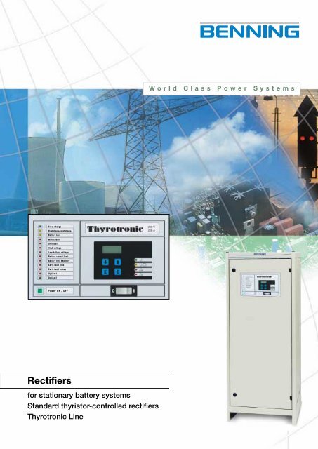
World Class <strong>Power</strong> SystemsFloat chargeFloat charge/boost chargeBattery testMains faultUnit faultHigh voltageLow battery voltageBattery circuit faultBattery test negativeEarth fault plusEarth fault minusOption 1Option 2<strong>Power</strong> ON / OFFRectifiersfor stationary battery systemsStandard thyristor-controlled rectifiersThyrotronic Line
1. General2. OperationIn all fields of industry and commerce theneed for auxiliary power supplies to protectequipment against power failure isincreasing. For many years the DC powersupply and battery combination have beenused in areas such as measurement, control,and data back up for the supply of thepower and protection of the load.Battery backed DC power supply systemsare used in a wide range of applications,such as, monitoring and controlling ofproduction processes, supply of measurementequipment, telemetry, telecomunicationand radio systems.Lead-acid and nickel-cadmium batteries achieve optimum servicelife when remaining on float, in a charge condition. The chargerfloats the battery in a charged state and also supplies the loadwith power. In the event of mains power failure the battery willthen supply the load its required power. This is called ”paralleloperation” (see fig. 2).With substantially discharged batteries, the rectifier unit atfirst operates in the I-branch of the IU-characteristic line, wherebythe charging current for the batteries results from the differencebetween the nominal current of the rectifier unit and the loadcurrent.When the set output voltage of the rectifier unit (U-branch) hasbeen reached, the unit is changed to constant voltage charging(see fig. 3).These systems can be found in:•• Hospitals<strong>Power</strong> plants and substations• Chemical plants• Petrochemical plants• Railway equipment• Offshore projects• Oil and gas pipeline systemsRectifier units presently employed for DC power supplies operatealmost without exception with a controlled output characteristic(IU-characteristic line in accordance with DIN 41773).The output voltage is keptconstant to the set valuewith a permissible deviationof ± 1 % within a loadrange between 0 % and100 % of the unit current.Mains voltage fluctuationsof ± 10 % and mainsfrequency fluctuations of± 5 % will be controlledautomatically by thethyristor regulator.Dependant on the application,flooded or valve regulatedlead-acid batteriesare the main mediumsused for energy storage inthe power supply systems,in some specialised applicationsnickel-cadmiumbatteries are also used.Fig.1:ThyrotronicrectifierFig. 2:Standby parallesoperationpower supply unitbatteryloadSwitching the charge characteristic,from float charging (e.g.2.23 V/cell with lead-acid batteries)to boost charging (2.4 V/cell withlead-acid batteries) gives an acceleratedrecharge which can be manual,dependent on voltage ordependent on voltage and time.After the battery has been fullycharged, a small charge currentflows (approx. 0.3 mA to 1 mAper 1 Ah) to balance the internallosses of the battery.
The required autonomy is taken into consideration for calculatingthe battery size. The standby times vary depending on type ofload and mains conditions.V/C2.4boost chargeFig 3: Charging characteristicfor lead-acid batteries inaccordance with DIN 417732.32.232.2float charge2.12.00020% 40% 60% 80% 100%I NTypical values:• 10 - 30 minutes for EDP-systems• 1 - 3 hours for DC power supply equipment in hospitalsand emergency lighting equipment3.• 2 - 10 hours for telecommunication systemsRectifier seriesThe Thyrotronic series operates with a thyristor-controlled powerunit which is combined with a microprocessor-controlled monitoringand control unit. The special feature of this series is theintegrated monitoring and signalling concept with the followingfunctions:Back up ofElectronic DataProcessingSystems• Mains monitoring•<strong>Charger</strong> output monitoring, current-dependentlow voltage monitoring• High voltage monitoring with impulse blockingBattery low voltage monitoring• Cyclic battery-circuit test• Battery availability test• Earth fault monitoring•Temperature-dependent floating charge voltage control(temperature sensor required)• IxR Compensation of voltage drop on the battery lead• Programmable automatic charging• Indication of operating mode• Active load sharing•Hardware basic setting of the controller in case ofprocessor fault• Interface for PC or laptop•Six digital ports for external monitoring functions
4. Integrated functionsThe frontpanel with integrated LED’s andthe LCD-display for indication of currentand voltage (see picture 4) enables theuse of different languages by way of anexchangeable inscription panel.The LED’s which are integrated beside thepush button in the display are providedfor fixed functions.Description of the integrated functions:Mains monitoringIn case of a mains failure , an electronic regulator block is placedand the LED and the "mains failure relay " will be activated. If themains volatge returns the unit is automatically switched on after aset time.<strong>Charger</strong> output monitoringoperationbattery operationgeneral failureThe charger output monitoring is a current-dependent low voltagemonitoring and monitors the IU-characteristic of the rectifier unit.If the charger output falls below a set value of 2,1 V/cell and theoutput current falls below 90 % of the rated current the alarm willactivate and indicate "unit fault".The corresponding LED and thecommon relay will be activated.urgent failureThe LED’s in the indicator panel have the following standard functions:• float charge•• battery test• mains fault• unit fault• high voltage••••••• option 1option 2float charge/boost chargelow battery voltagebattery circuit faultbattery test negativeearth fault plusearth fault minusFig.4: Front view of thethyristor rangeThyrotronicFloat chargeFloat charge/boost chargeBattery testMains faultUnit faultHigh voltageLow battery voltageBattery circuit faultBattery test negativeEarth fault plusEarth fault minusOption 1Option 2<strong>Power</strong> ON / OFFHigh voltage monitoringThere are 3 potential free relays for the following alarms• „mains failure“••„common alarm“„low battery voltage“.A relay card with a further 7 potential free alarm relays is availableas an option.If the output voltage rises too high (value is adjustable) due to aninternal or external interference, over 20 msec. The impulse blockingwill be activated and the output voltage will be set to zero.This high voltage monitoring works as dynamic monitoring withan automatic reset. If the monitoring responds 4 times within aperiod of 30 seconds, the mains contactor will be disconnected,the LED "high voltage" and common relay will be activated.
Low battery voltageIf the battery voltage falls below a set value, e.g. 1,8 V/cell (valueadjustable) during discharge in a case of mains failure, the alarm"low battery voltage" will appear. LED and common alarm will beactivated.Earth fault monitoringThe earth fault monitoring function monitorsthe insulation resistance of the DCoutputto earth. Plus and minus are measuredand monitored alternately. If theinsulation resistance falls below theadjusted value (adjustable from 100 kOhm to 1 MOhm), this willbe indicated by the LEDs and the common alarm.Use as powerstation powersupplyI*R CompensationWith I*R Compensation it is possible to balance the voltage dropon the cable between rectifier and battery by entry of cable lengthand cross-section of the cable.Battery circuit testThe battery circuit of the power supply system is tested cyclicallyevery 24 hours. For this, the rectifier output voltage is droppeddown to 1.9 V/C for a period of 5 secs. and, as a result, the batteryis discharged. At the same time, the battery voltage ischecked. If the battery voltage stays above 1.9 V/C, the batterycircuit will be all right. If it falls below the limiting value, a "batterycircuit fault" will be indicated and the LED as well as the commonfault signalling relay will be activated.Caution!It is not intended that this test should replace battery circuitmonitoring!Battery availability testProgrammable float/boost charge change overIf the battery voltage lowers due to mains failure or any other circumstancesthe rectifier unit will work in current limit. If it operatesfor more than 30 seconds after the charge start it will automaticallybe switched over to boost charge characteristic. Afterthe boost charge voltage (current limitation) has been reachedand after decreasing to < 90 %, a time stage will be activated.Upon expiry of the set time (0 to 6 h) it will automatically beswitched back to float charge.The automatic charging can be switched off so that only a manualswitch-over via the plastic foil key board on the front panel is possible.Switching back to float charge can be done manually aswell.If this is not done, the controller will switch back as in thecase of automatic charging.The switch-over to boost charge can be blocked by an externalcontact or a fixed bridge on the controller.During the battery availability test the rectifier output voltage willbe dropped and the battery will be discharged as it is the caseduring the battery circuit test. But the battery will be dischargeddown to an adjustable minimum voltage limit during anadjustable time. These limits depend on the proportional batterycapacity withdrawn during the discharge and can be taken fromthe discharging curves of the connected battery.If, during the availability test, the values fall below the adjustedlimits, the message "battery test negative" will be indicated by thecorresponding LED and the collective fault signalling relay.After the test the rectifier automatically switches back to boostcharge or floating charge.Equalise charge stageIt is possible to switch to an equalise charge stage via a switch onthe front panel.Here the voltage limitation will be abolished and the nominal unitcurrent will be reduced to 20 % (adjustable from 20-30).An equalise and comissioning charge follows with an I-characteristicup to the final charge voltage of the battery.
5. Technical dataHardware basic settingAfter switching to equalise charge, a timerautomatically switches back to the floatcharge on expiry of the set time (16 hoursto 72 hours).Using an external contact or a fixed bridgeat the regulator, the equalise charge canbe blocked and a switch over to theI-characteristic can be prevented.Active load sharingDue to an internal bus connetion betweenseveral rectifiers an active load sharingof ± 10 % is possible.Mains inputInput voltage:230 V ± 10 % single phase3 x 400 ± 10% three phaseInput current:see tableFrequency: 50 Hz ± 5 %Rectifier outputOutput voltage:24, 48, 60, 110, and 220 VOutput current:see tableAdjustment: ± 5 %Boast voltage:2,40 V/Z Pb battery1,55 V/Z NiCd batteryFloat voltage:2,23 V/Z Pb battery1,40 V/Z NiCd batteryEqualise voltage:2,70 V/Z Pb battery1,70 V/Z NiCd batteryRegulation tolerance: ± 0,5 %Ripple voltage:< 5 % eff without batteryfor option 2 % effCooling:self-coolingAmbient temperature: 40 °CProtection: IP 20Painting: RAL 7032Acoustic noise level:Max. 60 dB (A)Cabinet type:see tableIn the case of microprocessor failure in the control unit, the controllerinternally switches over to a basic setting. That is, the rectifiercontinues to operate at the adjusted floating charge voltageand supplies the load as well as the battery.In this case, a fault signal will be indicated by the common faultsignalling relay.OptionAs an option, the display and operation unit of MCU 2000 isavailable with a graphic and alphanumeric display.Additionally, the unitis equipped with anFloat chargeFloat charge/boost chargeinterface for remoteThyrotronicBattery testMains faultdata transfer.Unit faultHigh voltageLow battery voltageBattery circuit faultBattery test negativeEarth fault plusEarth fault minusOption 1Option 26. Cabinet type tableCabinet type H W DWGZ 755 758 534 470PSJ 1564 1500 600 400PSJ 1566 1500 600 600PSJ 1866 1800 600 600PSJ 1896 1500 900 600PS 220808 2200 800 800PS 221008 2200 1000 800PS 221208 2200 1200 800WGZ - wall mounted cabinetPSJ / PS - floor standing cabinet<strong>Power</strong> ON / OFF
7. Type tableNom.voltageV242424242424242424244848484848484848484848484860606060606060606060606060108108108108108108108108108108108108108108108216216216216216216216216216216216216216216216216No. ofcellsPb121212121212121212122424242424242424242424242430303030303030303030303030545454545454545454545454545454108108108108108108108108108108108108108108108108No. ofcellsNiCd202020202020202020204040404040404040404040404050505050505050505050505050909090909090909090909090909090180180180180180180180180180180180180180180180180TypeE 230 G 24 / 20 BWrug-TDGE 230 G 24 / 40 BWrug-TDGE 230 G 24 / 60 BWrug-TDGE 230 G 24 / 80 BWrug-TDGD 400 G 24 / 100 BWrug-TDGD 400 G 24 / 125 BWrug-TDGD 400 G 24 / 160 BWrug-TDGD 400 G 24 / 200 BWrug-TDGD 400 G 24 / 300 BWrug-TDGD 400 G 24 / 400 BWrug-TDGE 230 G 48 / 10 BWrug-TDGE 230 G 48 / 20 BWrug-TDGE 230 G 48 / 30 BWrug-TDGE 230 G 48 / 40 BWrug-TDGD 400 G 48 / 50 BWrug-TDGD 400 G 48 / 60 BWrug-TDGD 400 G 48 / 80 BWrug-TDGD 400 G 48 / 100 BWrug-TDGD 400 G 48 / 125 BWrug-TDGD 400 G 48 / 160 BWrug-TDGD 400 G 48 / 200 BWrug-TDGD 400 G 48 / 300 BWrug-TDGD 400 G 48 / 400 BWrug-TDGE 230 G 60 / 10 BWrug-TDGE 230 G 60 / 20 BWrug-TDGE 230 G 60 / 30 BWrug-TDGE 230 G 60 / 40 BWrug-TDGD 400 G 60 / 50 BWrug-TDGD 400 G 60 / 60 BWrug-TDGD 400 G 60 / 80 BWrug-TDGD 400 G 60 / 100 BWrug-TDGD 400 G 60 / 125 BWrug-TDGD 400 G 60 / 160 BWrug-TDGD 400 G 60 / 200 BWrug-TDGD 400 G 60 / 300 BWrug-TDGD 400 G 60 / 400 BWrug-TDGD 400 G 108 / 5 BWrug-TDGD 400 G 108 / 10 BWrug-TDGD 400 G 108 / 16 BWrug-TDGD 400 G 108 / 25 BWrug-TDGD 400 G 108 / 30 BWrug-TDGD 400 G 108 / 40 BWrug-TDGD 400 G 108 / 50 BWrug-TDGD 400 G 108 / 60 BWrug-TDGD 400 G 108 / 80 BWrug-TDGD 400 G 108 / 100 BWrug-TDGD 400 G 108 / 125 BWrug-TDGD 400 G 108 / 160 BWrug-TDGD 400 G 108 / 200 BWrug-TDGD 400 G 108 / 300 BWrug-TDGD 400 G 108 / 400 BWrug-TDGE 230 G 216 / 5 BWrug-TDGD 400 G 216 / 10 BWrug-TDGD 400 G 216 / 16 BWrug-TDGD 400 G 216 / 20 BWrug-TDGD 400 G 216 / 25 BWrug-TDGD 400 G 216 / 30 BWrug-TDGD 400 G 216 / 40 BWrug-TDGD 400 G 216 / 50 BWrug-TDGD 400 G 216 / 60 BWrug-TDGD 400 G 216 / 80 BWrug-TDGD 400 G 216 / 100 BWrug-TDGD 400 G 216 / 125 BWrug-TDGD 400 G 216 / 160 BWrug-TDGD 400 G 216 / 200 BWrug-TDGD 400 G 216 / 300 BWrug-TDGD 400 G 216 / 400 BWrug-TDGMain Curr. Cabinetvoltage consump. typeVA230 4,6 WGZ 755230 9,2 WGZ 755230 13,6 PSJ 1564230 17,8 PSJ 15643 x 400 5,5 PSJ 15643 x 400 6,8 PSJ 15643 x 400 8,7 PSJ 15643 x 400 10,8 PSJ 15643 x 400 19,0 PSJ 15643 x 400 24,3 PSJ 1596230 4,6 WGZ 755230 9,1 WGZ 755230 12,3 PSJ 1564230 16,3 PSJ 15643 x 400 5,8 PSJ 15643 x 400 6,7 PSJ 15643 x 400 8,9 PSJ 15643 x 400 10,8 PSJ 15643 x 400 13,8 PSJ 15643 x 400 17,6 PSJ 15643 x 400 21,9 PSJ 18663 x 400 32,0 PSJ 18663 x 400 48,0 PSJ 1896230 5,1 WGZ 755230 10,3 WGZ 755230 17,5 PSJ 1564230 20,4 PSJ 15643 x 400 6,8 PSJ 15643 x 400 8,1 PSJ 15643 x 400 10,8 PSJ 15643 x 400 13,5 PSJ 15643 x 400 17,1 PSJ 15643 x 400 21,7 PSJ 15643 x 400 26,5 PSJ 18663 x 400 40,5 PSJ 18663 x 400 53,0 PSJ 1896230 4,0 WGZ 755230 8,0 WGZ 755230 13,2 PSJ 15643 x 400 6,5 PSJ 15643 x 400 7,5 PSJ 15643 x 400 10,0 PSJ 15643 x 400 12,9 PSJ 15643 x 400 14,7 PSJ 15643 x 400 20,0 PSJ 15643 x 400 24,7 PSJ 18663 x 400 31,5 PSJ 18663 x 400 40,0 PSJ 18663 x 400 50,0 PSJ 18963 x 400 70,0 PSJ 18963 x 400 100,0 PS 220808230 9,4 WGZ 7553 x 400 5,1 PSJ 15643 x 400 8,0 PSJ 15643 x 400 9,8 PSJ 15643 x 400 12,4 PSJ 15643 x 400 15,2 PSJ 15643 x 400 21,0 PSJ 15643 x 400 25,2 PSJ 18663 x 400 30,5 PSJ 18663 x 400 40,0 PSJ 18663 x 400 50,0 PSJ 18963 x 400 63,0 PSJ 18963 x 400 81,0 PSJ 18963 x 400 100,0 PS 2208083 x 400 152,0 PS 2212083 x 400 203,0 PS 221208WeightKg30406075150200240290400510304060751451902202702903404005006003040607515022025028030035042052062030406075951802202603304004505005208501100406080120220260330400450500620720800105013001600Subject to technical change without notice.
<strong>BENNING</strong> World Class <strong>Power</strong> Systemswww.benning.de<strong>BENNING</strong> worldwideAustriaBenning GmbH Elektrotechnik und ElektronikEduard-Klinger-Str. 9A-3423 St. Andrä-WördernTel. 0 22 42 / 3 24 16-0Fax 0 22 42 / 3 24 23E-Mail: info@benning.atIndiaBenning SMC <strong>Power</strong> Systems (P) <strong>Ltd</strong>.10, Electronic City, Sec.-18,IND-Gurgaon -122015, HaryanaTel. 0124 / 6 45 52 03 – 09Fax 0124 / 6 45 52 12, 6 34 64 65E-Mail: smcel@del2.vsnl.net.inRussian FederationOOO Benning <strong>Power</strong> ElectronicsSchtscholkovskoje Chaussee, 5RF-105122 MoscowTel. 095/9676850Fax 0 95 / 9 67 68 51E-Mail: benning@mtu-net.ruBelgiumBenning Belgium<strong>Power</strong> ElectronicsZ. 2 Essenestraat 16B-1740 TernatTel. 02 / 58 287 84 (85)Fax 02 / 58 287 69E-Mail: info@benning.beIrelandTheo Benning GmbHNorth <strong>Industrial</strong> EstateWhitemill NorthIRE-Wexford / Rep. IrelandTel. 0 53 / 41 79 5Fax 053/41841E-Mail: benning@benning.ieSouth East AsiaBenning <strong>Power</strong> Electronics Pte <strong>Ltd</strong>1, Kaki Bukit View# 05-03/04 TechviewSGP-Singapore 415941Tel. (65) 6844 3133Fax (65) 6844 3279E-Mail: benning@singnet.com.sgCzech RepublicBenning CR s.r.o.Zahradní ul. 894CZ-293 06 Kosmonosy(Mladá Boleslav)Tel. 03 26 / 72 10 03Fax 03 26 / 72 25 33E-Mail: benning@benning.czIsraelLaor Energy ltd.P.O.B. 570IL-Nazereth Elite 17105Tel. 03 / 6 87 25 51Fax 03/6871110E-Mail: URI@Laor-Energy.comSwedenEldaco ABBox 990, Hovslagarev. 3BS-19129 SollentunaTel. 08 / 6239500Fax 08 / 969772E-Mail: power@eldaco.seFranceBenning Conversion d’énergie43, avenue Winston ChurchillB.P. 418F-27404 Louviers CedexTél. 02 / 32 25 23 94Fax 02 / 32 25 08 64E-Mail: info@benning.frItalyBenning Conversione di Energia S.r.l.Via E. Mattei, 7I-40138 BolognaTel. 0 51 / 53 19 55Fax 0 51 / 53 09 23E-Mail: benning.energia@libero.itSwitzerlandBenning <strong>Power</strong> Electronics GmbHIndustriestrasse 6CH-8305 DietlikonTel. 01/ 8057575Fax 01/ 8057580E-Mail: info@benning.chISO 14001GermanyTheo BenningElektrotechnik und Elektronik GmbH & Co.KGMünsterstr. 135-137D-46397 BocholtTel. 0 28 71/ 93-0Fax 02871/93297http://www.benning.deGreat-BritainBenning UKOakley HouseHogwood LaneFinchampsteadGB-Berkshire RG 40 4 QWTel. 0 11 89 / 73 15 06Fax 0 11 89 / 73 15 08E-Mail: info@benninguk.comHungaryBenning Kft.<strong>Power</strong> ElectronicsRákóczi út 262H-2541 LábatlanTel. 033/507600Fax 033/507601E-Mail: benning@mail.uti.huNetherlandsBenning NL<strong>Power</strong> ElectronicsPeppelkade 42NL-3992 AK HoutenTel. 030/6346010Fax 0 30 / 6 34 60 20E-Mail: info@benning.nlPolandBenning <strong>Power</strong> Electronics Sp.z.o.o.Korczunkowa 30PL-05-503 GloskówTel. 0 22 / 7 57 84 53 / 7 57 36 68-70Fax 0 22 / 7 57 84 52E-Mail: benning@medianet.plP. R. of ChinaBenning V. GmbHShanghai Repr. Office1233 Si Ping Rd., Rm. 006PRC-200 092 ShanghaiTel. 021 5557 0609Fax 021 6504 1878E-Mail: benning@public8.sta.net.cnSpainBenning Conversión de Energía S.A.C/Pico de Santa Catalina 2Pol. Ind. Los LinaresE-28970 Humanes, MadridTel. 91/ 6048110Fax 91/ 6048402E-Mail: benningcde@retemail.esUkraineBenningul. Solomenskaja, 3BUA-252110 KiewTel. 044 / 246 10 25Fax 044 / 248 92 36E-Mail: benning@ukrpack.netU.S.A.Lucas-Benning<strong>Power</strong> Electronics, Inc.11120 Grader StreetUSA-Dallas, TX 75238Tel. 214 5531444Fax 214 5531355E-Mail: sales@lucasbenning.com784144.00 02/2002 paus Design & Medien, Bocholt Subject to alterations. Printed on chlorine free paper.


