5.6MB - M-System
5.6MB - M-System
5.6MB - M-System

You also want an ePaper? Increase the reach of your titles
YUMPU automatically turns print PDFs into web optimized ePapers that Google loves.
Computers and electronic instrumentsare essential for processingvarious kinds of informationin a high speed manner. However,they are often subject tothe induced energy caused bylightning, because of their generallylow dielectric strength.Lightning is a phenomenon inwhich negative electric chargesgenerated in a thunderstorm dischargeto the ground as a resultof dielectric breakdown in theair. A lightning surge, even anindirect one, causes a surgevoltage on the cable lines, andtransmits a momentary high voltageimpulse to the sensors /transmitters in the field, or to theinputs of computers and instrumentsin the control room.2 3
Emergence of thundercloudThere are a variety of theories how thunderclouds emerge, but generally it is explained as below.When atmosphere near the earth surface or ocean surface containing a large amount of water vaporwarms up by the heat from the sun and other sources, it expands and ascends. When it reaches a highaltitude, it is cooled down, resulting the vapor in the atmosphere becomes water droplets and then acloud. When it ascends even higher, water droplets in the cloud becomes ice grains and some of themconcentrate and grow to hailstones.At that time, these ice grains and hailstonesare decomposed by electric current.Then, ice grains are charged positively andhailstones are charged negatively. Icegrains ascend even higher by riding updraftand hailstones grow bigger and fall bythe gravity. Charge separation continuesby the coulomb force. Before long, top ofthe cloud is positively charged and the bottomnegatively. A cloud accumulates electricalenergy, which is when a thundercloudemerges.What is lightning surge?Figure 1-1ice grainhailstoneWhen electric charges are built up in thunderclouds to such level that could break atmospheric insulation,an electric discharge eventually occurs between these clouds or between the clouds and theground. Electric current reaches 20-150 kA.An abnormally high voltage generated by direct lightning discharge applied to electric power cables orcommunication cables at that instance is called ʻdirect lightning surgeʼ.Correspondingly, such voltage induced by electrostatic or electromagnetic induction on those cables locatedclose to the point where a direct lightning hits, is called ʻinduced lightning surgeʼ.Also, when lightning strikes a lightning rod and the ground potential rises, instrumentsʼ grounding potentialbecomes also high. This causes an abnormally great potential difference between the cables andthe ground, which is called ʻlightning surge caused by increased ground potentialʼ.Direct lightning surge energy is enormous. A surge protector alone cannot protect the instruments. It isnecessary to share the job by lightning rods and overhead grounding wires to absorb most of the energy,and by surge protectors to absorb only the rest of the energy.Here, we explain the mechanism how lightning surges occur, except for the direct lightning surge.Electrostatic inductionWhen thunderclouds located above a power cable orcommunication cable contain negative charges attheir bottom parts, high level positive charges are inducedelectrostatically within the cable and high voltageis developed by electrostatic induction from thunderclouds(Figure 2-1).At that instance, the negative charge at the bottom ofthe thundercloud disappears by discharging betweenthe clouds or between the clouds and the ground.Then, the positive charge which is trapped by the cableare freed and led to both directions on the cableas a surge voltage (Figure 2-2).Electromagnetic inductionA discharge between the clouds and the ground occurringnear from a power cable or communicationcable generates a magnetic field due to its surge current.When the magnetic waves propagated withinthe field reach the cable, a lighting surge is induced(Figure 3-1).Increased ground potentialWhen lightning strikes a building or a lightning rod,high current flows to the ground and the ground potentialrises. This causes a potential difference betweenthe equipment No. 1 located close to the lightningrod (high potential) and the equipment No. 2 locatedfar away from it (low potential), and as a resultthe lightning surge is directed from the ground to thecable between these locations (Figure 4-1).In addition, if a building is in charged state by thunderstormʼselectrostatic induction, an atmosphericdischarge dissipating the electric charge at the bottomof the cloud causes the electric charge on thebuilding to flow toward the ground. This also leadsthe ground potential to rise and the lightning surge directedto the cable from the ground (Figure 4-2).Figure 2-1induced lightning surgeFigure 2-2thundercloudinducedlightning surgeFigure 3-1increasedground potentialsurgecurrentgroundresistanceFigure 4-1thundercloudnegative chargethundercloudthunderclouddischargelightninglightning rodinduced positive chargemagneticfieldpylondischargeinduced lightning surgepyloninducedlightning surgepylonequipment No. 1lightning surgerelativepotentialdifferencechargeddischargebetween cloudselectric chargedissipatedequipment No. 2thunderclouddischargedFigure 4-2increasedground potential4 5
Entry pathway of lightning surgeDue to the online application of modern electronic systems, there are multiple interfacing parts to theoutside for an instrument. One of such interface parts is signal cable and the other one is power cable.These cables pulled from the outside can be perfect entry pathways for the lightning surge.The effects of induced surge on a connected device will be more severe when the connected cable islonger and the device is located closer to the place where the actual lightning strikes. Even lightningrods with minimal cable length do not alwaysprotect as they are hoped.Discharge breakdown (V2, V3)Lightning surges cause a very high potential (voltage)difference between two conductors and theground, and a discharge occurs between some partof an electronic circuit and those electrically connectedto the ground, such as metal housings.Electronic components become damaged becausesome of the discharge current flows through theelectronic circuit (Figure 6-1).lightning surgecableFigure 6-1V3V1V2+–instrumentGgroundThe effect of lightning surges dependsupon the cable location and its environment.Surge protectors installed in thosepaths absorb and eliminate the high voltageimpulse energy and protect the electricinstrument from damage (Figure 5-1).signallineFigure 5-1surgeprotectorGgroundingsystemGGpowerlineFundamentals of surge absorbingInduced lightning is a current source which tries to flow the current. This current is the lightning surgecurrent. When current does not flow smoothly, it generates high voltage and forces to let the currentflow. The high voltage generated at that time is lightning surge voltage.Breaking mode of electrical instrumentSurge voltage generated between a cable and the ground might reach several tens of thousands of volt,however, lightning occurs at a voltage typically five thousand volts between the cable and the ground,while it induces several hundred volts between lines.When analyzing breaking condition of the instrument, it is often broken by this line voltage. We call itʻinterline breakdownʼ. Characteristics of interline breakdown is that semiconductor parts near the entrypoint of lightning surge breaks.Also, breaking mode between the cable and the ground is called ʻdischarge breakdownʼ. Because thelightning surge voltage is very high against that of the ground, an arc discharge is generated betweenan electronic circuit and a grounded enclosure. Characteristics of discharge breakdown is that weakpart of insulation between the circuit and enclosure breaks down.M-<strong>System</strong>ʼs surge protectors keep the surge voltage level at which instrument does not get damagedand prevent interline breakdown and discharge breakdown.Now, let us explain the fundamentals of lightning surge protector. Here we explain them with an exampleof a most commonly used model, the MDP-24-1. The diagram below is a simplified circuit of theMDP-24-1. On the cable, lightning surge voltage V1-V3 is generated to let the current flow. We call V1,interline surge voltage, and V2 and V3, line to ground surge voltage.The surge protector absorbs V1 at the discharge element SA1 and V2 and V3 in SA2 and SA3. SA1-SA3 can be considered as voltage-dependant switches. When the voltage is high, an arc is dischargedand they suppress the arc discharge of V1-V3 around 30V. It is important to limit the surge voltage aslow as possible. Especially, V1, which is applied directly to the protected instrument, is eliminated by thedischarge element SA1 and the voltage limiting element D1.SA can bypass high current, however, its firing potential is high and the setting voltage varies widely. Inorder to compensate these disadvantages, it is combined with D1 of which firing potential is low and thesetting voltage does not vary much and suppresses the surge voltage to a low level. D1, which doesnot tolerate high current, is also protected by R1 which limits the surge current (Figure 7-1).The discharge element and the voltage limiting element together are called the surge absorber element.Since there is no one ideal surge absorber element, i.e. small size, small setting voltage variation, fastresponse time, high discharge withstand current rating, no failure in shortcircuit mode, the surge absorbercircuit is designed with combinations of components to bring out their good characteristics.Interline breakdown (V1)This occurs when the surge voltage between cables is directly applied to the electronic components inthe instrument. Usually, only these components that are located near the termination of the cablewhere the surge entered are destroyed.surgecable resistanceSSA1V1 V3SV2 SA2 SA3R1D1PP+–protecteddeviceelectriccircuitryGGFigure 7-16 7
Surge protector selectionMaximum surge voltage (clamping voltage)The maximum surge voltage of the surge protector must be lower than withstand voltage of the protectedinstrument (Figure 8-1).Discharge current capacityM-<strong>System</strong>ʼs surge protectors have different ratings from 1 kA to 20 kA. Choose an appropriate ratingconsidering how often lightning strikes your installation and how important is to protect the instrument(Figure 8-2).Surge protectors for power lineMaximum load current up to 200 A is selectable. Single-phase/two-wire, single-phase/three-wire, threephase/three-wireand DC power supply systems are selectable. Choose one based on the load currentand the number of phase.Points of caution when installing surge protectorsGroundingMaximum load currentChoose an appropriate model considering how much current, in mA, you need it flow for a signal line orhow much power, in VA, you need for a power line.Maximum line voltageThe maximum line voltage must be higher than the rated voltage of protected instrument (Figure 8-2).Vsurge voltagesurgesurge protectorprotected deviceNot only surge protectors, but also computer systemsand electronic instruments are connected to the earthgrounding to prevent noise interference. Make thecrossover wire thick and short to prevent a potentialdifference built up between the protectorʼs earth terminaland the instrumentʼs earth when the line is subjectedby a precipitous rise of lightning surge.There are reports saying that only one instrumentsamong many has been damaged because this onewas left unconnected to the ground with a crossoverwire after the connection had been taken out during aregular checkout (Figure 9-1).signal cablelightning surgepower cableFigure 9-1circuitbreakersurgeprotectorGprotecteddevicesurgeprotectorGGcrossover wiringgroundwithstand voltage of theprotected instrumentmax. surge voltage Vcdischargecurrent capacitytFigure 8-1 Figure 8-2Which surge protector do you choose?Surge protectors for signal linedischargeelementgroundingmax. linevoltageratedvoltagemax. line voltage > rated voltageM-<strong>System</strong>ʼs surge protectors are classified according to sensor/signal types, such as standard 4-20 mAsignal, RTD, thermocouple, potentiometer, strain gauge and pulse generating device. We also havethose specific for various field networks such as RS-485, Ethernet, PROFIBUS and DeviceNet.Insulation testBefore performing the insulation test for an instrumentpanel equipped with lightning surge protectors,you must disable the surge protectors because theywill start discharging during the test and possiblycause insulation failures.With signal line protectors, simply unplug the elementfrom the base socket.With power supply line protectors, remove all thegrounding wires connected to the ground terminal.Be sure to re-connect all wires back after the test iscompleted.Two-wirepowersourceThree-wirepowersourcecircuitbreakercircuitbreakersurge protectorfor power lineGsurge protectorfor power lineGUVUVWprotecteddeviceGprotecteddeviceG[Example]Figure 9-2A 2-wire transmitter in general transmits 4 to 20mA DC output signal, powered by 24V DC power sourceon the same loop.Choose the lightning surge protector for standard signal (ex. MDP-24-1). Both transmitter and controlroom instrument incorporate electric circuits. Therefore, surge protectors are needed at the both side.In case of RTD, choose the lightning surge protector for RTD use (ex. MDP-RB). Even though the sensorhas no electric circuit, a surge protector should be connected at the detection side in order to preventthe platinum resistance probe from breaking, in addition to the transmitter side.Molded-case circuit-breakerA power supply line protector usually incorporates a circuit protector, however, it may not be able tohandle a lightening surge far exceeds its discharge withstand current rating such as direct lightningstrike.Be sure to set a molded-case circuit breaker. Choose one that its current rating is equivalent to the maximumload current of the surge protector (Figure 9-2).8 9
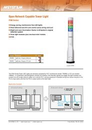
Ultra-Slim Lightning Surge ProtectorsSeriesNEW• High-density mounting with 7-mm widemodules• Excellent protection by multi-stage SPD• Max. discharge current 20 kA (8/20 µsec.)• Floating mode for the shield to avoidground loops• DIN rail mounting / grounding• Loop disconnect fuse (option)INDEPENDENT SHIELD TERMINALFloating and grounding modes are selectable in free combination between shield and signal,shield and ground.In the floating mode, the shield is normally insulated from the signal and the ground by a dischargeelement. When an elevated potential is detected by a lightning surge, the discharge elementis immediately activated to prevent discharge at an undesirable location.In the grounding mode, the shield is normally connected via the signal line with a low potentialdifference of several to several tens of volts, and connected permanently to the ground.Each installation or network protocol requires different earth grounding method, such like bothendgrounding, single-end grounding, SG terminal connection. The MD7 Series provide themost suitable grounding type for each application.MD7 Series function digram and wiring example.LOOP DISCONNECT FUSEThe model MD7ST, designed specifically for 4-20mA loop, is provided with fuses to disconnect afailed device from the power bus supplying multipledevices. When the device protected by the MD7STfails in shortcircuit mode, the fuse separates it fromthe power bus and protects the entire system.M-<strong>System</strong>ʼs MD7 Series are lightning and surge protectors for instrumentation signal, network andpower supply. Housed in only 7-mm-wide ultra slim housings, 16 surge protectors lined side by sidetake only 110-millimeter wide space. With the height and depth similar to PLCs and remote I/Os, theyare ideal to be installed in panels and cabinets together with these instruments.Four poles of terminals are equipped on each of surge side and protected side, three for signal andone for shield. By adapting an independent set of shield terminals, floating and grounding can be selectedin free combinations to suit usersʼ applications.HIGH PERFORMANCEThe multi-stage protection combining dischargeelements at the first stage and theseries resistances and diodes ensures tolimit the current flow.The maximum discharge current capacityis as high as 20 kA for an impulse wave of8/20 microseconds. The MD7 Series aretested according to IEC 61643-21 standardto be suitable for categories C1, C2and D1. C1 category requires the surgeprotector to withstand 300 times of averageinduced surges, C2 to withstand 10times of strong induced surges generatedin a harsh environment without electromagneticshielding. D1 category is testedby two direct hits.EASY COMMISSIONING95 (3.74)7 (.28)Wide adaptabillity:4-pole terminals8654Loop disconnectfuse (MD7ST)1 12Power LED37 (MD7DP)Only 7 mmwide3798 (3.86)The MD7 Series are designed for multi-point, ultra-high-density installation. DIN rail mounting/grounding and slantedterminal block help installation and wiring work in such tight space.When the DIN rail is grounded at single point, surge protectors mounted on it are automatically connected to theearth. There is no need of cross-wiring individual module.Thanks to the terminal blocks slightly slanted forward, access from the front side to the terminals is easy even afterthe protectors are mounted on the rail.4Easy wiring: Slanted terminals5268DIN railmounting /groundingunit: mm (inch)8-Port Ethernet Switch with Surge ProtectorLAN PORT SPECIFICATIONSNEW• Optional surge protector function for each port• Protects Ethernet devices from surges entering through LAN cables• Surge protector life monitor function with LED and contact output alarm• Data transfer rate can be fixedStandardsNumber of portsData transfer rateIEEE 802.3, IEEE 802.3u, IEEE 802.3x8; All ports support AUTO-MDIX*10 Mbps (10 BASE-T),100 Mbps (100 BASE-TX);Supports Auto-NegotiationCableMaximum segment lengthSwitchingFull duplex10 BASE-T (STP cable, category 5)100 BASE-TX (STP cable, category 5e)100 metersStore & ForwardPAUSE FramesFlow controlBufferHalf duplex Back pressure64 KBMAC address table 1024* Automatically sensing cable type (straight-through or cross-over).SURGE PROTECTOR PERFORMANCECompliant standardBetween portsPort to GFG (shield) to GVoltage protection levelPort to FG or GBetween each portFG to GEN61000-4-5 level X1kV (combination waveform)**10kV (combination waveform)20kV (combination waveform)***160V min.160V min.160V min.(with the shortcircuit bar removed)** RJ-45 connector contact is out of the scope of this protection.Using twisted-pair (STP) LAN cable is effective to reduce risk of fusing contact.*** With the shortcircuit barFRONT VIEWLINK LED100M LEDLAN Ports (x 8)RJ45 ConnectorStatusDevice status LEDProtector * 1Surge Protector LifeMonitor LED*1. Provided only with the surgeprotector option.10 11
Lightning Surge Protectors with Life MonitorOne-Port Surge Protector For Power Supply Use• Designed specifically for 4-20 mA DC andpulse signal line including 4-wire/2-wiretransmitters.• Battery powered life monitoring systemincludes a ʻTestʼ button with indicators alertingpanel inspectors of the surge protectorʼsʻhealth.ʼ• Upgrades M-<strong>System</strong>ʼs MDP-24-1 to the lifemonitor type simply by replacing the pluggableelement module with one for the MDPA-24.Without question, the main complaint in the industry with regard to lightning surge protectors is the difficultyin determining whether the lightning surge protector installed to protect your control system components isstill functional.Consider opening a panel with a large number of surge suppressors. Instead of unplugging and testing everyunit, for M-<strong>System</strong>ʼs life monitor series models MDPA-24 and MDPA-65, all that is necessary is a quickvisual inspection with a push button. No further tools or checking are required.The lightning surge protector models MDPA-24 and MDPA-65 monitor not only the number of suppressedsurges across the signal lines but also the leakage current from signal to ground which gives you more precisewarning than most typical surge protectors monitoring only the number of suppressed surges. When apredetermined level of either the leakage current or number of suppressed surges is exceeded, respectiveindicators illuminate with a prompt of the ʻTestʼ button.Low in cost, these devices pay for themselves by providing early warning alarms and reducing ongoing unnecessarypanel maintenance. When it comes to comparing the cost of downtime versus lightning surgeprotector replacement, the choice is obvious.If you already have M-<strong>System</strong>ʼs models MDP-24-1 or MDP-65-1 installed in your instrumentation panels, replacingonly their element modules with ones for the MDPA-24 or MDPA-65 upgrades the system to life monitorvery economically.If you need to be alerted automatically and remotely of the surge protectorʼs life, the auxiliary powered modelsMDM2A-24 and MDM2A-65 can provide an alarm contact output.How many surge devices does your company have installed that are potentiallyin poor health and still ‘protecting’ your control system?ElementCHK CheckButtonBaseBATIndicatorLEDALMIndicatorLEDLIFE MONITOR FUNCTION■ LIFE INDICATIONIndicators (Activated by CHK [Check] button)BAT (battery): Green LEDALM (alarm): Red LEDDischarge element status tableBAT: ONALM: OFFBatteryNormalNormalDischargedDischargeElementNormalNear EndEnd of LifeVoltageLimiterNormalDegradedUnable to Judge* 1ReplacementNo NeedNearImmediatelyRequired* 1 With pulsating line signal or that containing ripples, the LED mayflicker or blink when the voltage limiter is degraded.• Designed to protect electronics equipment from induced lightning surges enteringthrough power supply cables• Connected in parallel between the power and ground lines regardless of loadcurrent• Varistor discharge element has a high speed response without follow current.• No interruption of power supply even when the head element is removed:easy maintenance and replacing• Degraded head element is automatically separated from the power lines toprevent overheating, with a relay contact output to alert the failure status.• Head-base connection is keyed so that only a head element of correct line voltage can be mounted.SURGE CURRENT FLOW (cross section)Terminal BlockConnection TypeLightning SurgeM5 screw (spring loaded)GroundMetal OxideVaristor (MOV)CONNECTION DIAGRAM & GROUNDING (MD6T)Field (Protected Equipment Enclosure) Central StationProtectedEquipmentMD6TMDP-24-1MDP-65-1Current LoopSupply+ + yellow +1S+ P+ +SensorCableIN– ––blue 2S– P– –green To Central Station GG(ProtectedEquiment)GGTHERMAL BREAKER (cross section)Breaker Operation312The alarm output switch is turned on.When the low temperature-melting solder ismelted by an abnormal high temperature atthe discharge element, the lever mechanismis released by the force of spring to separatethe discharge element from the circuit.The green failure indicator turns to black atthe same time.CONNECTION EXAMPLESSingle-phase / 2-wire connectionProtected DeviceGCross-wiringGroundingLeadwire Connection,Pipe Nipple TypeSingle-phase / 3-wire,three-phase / 3-wire connectionProtected DeviceGCross-wiringGroundingLightning Surge Protector For Standard Signal Line & Pulse UseSeriesLeadwire Connection,MD6T MD6N MD6PStopping Plug Type• D e s i g n e d s p e c i f i c a l l y f o r 4 - 20 m A D C a n d p u l s e s i g n a l l i n e i n c l u d i n g b o t h 4 - w i r e a n d 2 - w i r e t r a n s m i t t e r s• D i r e c t m o u n t i n a w i r i n g c o n d u i t o f o u t d o o r e n c l o s u r e s• A b s o r b i n g s u r g e s o n l y w i t h o u t a f f e c t i n g i n s t r u m e n t a t i o n s i g n a lCONNECTION DIAGRAM & GROUNDING (MD6N)SensorField (Protected Equipment Enclosure)Protected MD6NEquipment+–G+–GGyellowredblue blackgreen+–CableTo CentralStationCentral StationMDP-24-1MDP-65-1Current LoopSupplyS+ P+ +INS– P– –G(ProtectedEquiment)12 13
STANDARD SIGNAL LINE USESENSOR SIGNAL USE4-20 mA & Pulse Signal, Ultra-slim TypeMD7ST-24 / MD7ST-60NEWModel No.MD7ST-24 MD7ST-60Max. Cont. Operat. Volt. (Uc)Voltage Protection Level (Up)30V60V max.70V115V max.Response TimeMax. Discharge Curr. (Imax)Nominal Current (IN)4 nanosec. max.20 kA (8/20 µs),1.0 kA (10/350 µs.)250 mAInternal Resistance4.7Ω w/o fuse 10Ω w/o fuse(Ω±10%, per line)7.5Ω w/ fuse 12.5Ω w/ fuseTest StandardIEC61643-21(Categories C1, C2, D1)Three-Wire Transmitter Loop,Ultra-slim TypeMD73FReleased July 2007NEWThermocouple, Ultra-slim TypeMD7TCModel No.Max. Cont. Operat. Volt. (Uc)Voltage Protection Level (Up)Response TimeMax. Discharge Curr. (Imax)Nominal Current (IN)Internal ResistanceTest StandardNEWMD7TC7.5V25V max.4 nanosec. max.20kA (8/20 µsec.),1.0kA (10/350 µsec.)100 mA4.7Ω ±10% per lineIEC61643-21(Categories C1, C2, D1)Thermocouple, Plug-in TypeMDP-TCModel No.Discharge VoltageMax. Surge VoltageResponse TimeDischarge CurrentMax. Load CurrentInternal ResistanceMDP-TC7.5V min.16V max.0.1 µsec. max.5000A (8/20 µsec.)100 mAapprox. 20 Ω (incl. return)Two-Wire Transmitter Loop,Ultra-slim TypeMD72F4-20 mA & Pulse Signal, Plug-in TypeMDP-24-1 / MDP-65-1Model No.Discharge VoltageMax. Surge VoltageResponse TimeDischarge CurrentMax. Load CurrentInternal Resistance4-20 mA & Pulse Signal,Plug-in Type, with Life MonitorMDM2A-24 / MDM2A-65LIFEMONITORReleased July 2007Model No.Discharge VoltageMax. Surge VoltageResponse TimeDischarge CurrentMax. Load CurrentInternal Resistance4-20 mA & Pulse Signal, High Speed,High Discharge Current CapacityMMDH-24Model No.Discharge VoltageMax. Surge VoltageResponse TimeDischarge CurrentMax. Load CurrentInternal ResistanceNEWMDP-24-1 MDP-65-130V min. 70V min.40V max. 80V max.4 nanosec. max.5000A (8/20 µsec.)100 mAApprox. 20 Ω (incl. return)MDM2A-24 MDM2A-6530V min. 70V min.45V max. 85V max.0.1 µsec. max.5000A (8/20 µsec.)100 mAApprox. 20 Ω (incl. return)MMDH-24±40V min.±50V max.4 nanosec.20000A (8/20 µsec.)100 mA0.4 Ω max. (incl. return)Two-Wire Transmitter Loop,Ultra-slim Type, with Life MonitorMD7A2FLIFEMONITOR4-20 mA & Pulse Signal,Plug-in Type, with Life MonitorMDPA-24 / MDPA-65LIFEMONITORFuture PlanModel No.Discharge VoltageMax. Surge VoltageResponse TimeDischarge CurrentMax. Load CurrentInternal Resistance4-20 mA & Pulse Signal, Low Profile TypeMDK-24Model No.Discharge VoltageMax. Surge VoltageResponse TimeDischarge CurrentMax. Load CurrentInternal Resistance4-20 mA & Pulse Signal,Conduit Mount, Weather-ProofMD6T-24 / MD6T-65MD6N-24 / MD6N-65MD6P-24 / MD6P-65(Terminal Block Connection Type)(Leadwire Connection, Pipe Nipple Type)NEWMDPA-24 MDPA-6530V min. 70V min.45V max. 85V max.4 nanosec. max.5000A (8/20 µsec.)100 mAApprox. 20 ΩMDK-2430V min.40V max.0.1 µsec. max.5000A (8/20 µsec.)100 mA20 Ω ±5%(Leadwire Connection, Stopping Plug Type)Model No.Discharge VoltageMax. Surge VoltageResponse TimeDischarge CurrentMax. Load CurrentInternal ResistanceMD6T-24 / MD6N-24MD6P-24MD6T-65 / MD6N-65MD6P-6570V min.100V max.30V min.40V max.4 nanosec. max.10000A (8/20 µsec.)100 mAApprox. 22Ω (incl. return)RTD, Ultra-slim TypeMD7RBModel No.Max. Cont. Operat. Volt. (Uc)Voltage Protection Level (Up)Response TimeMax. Discharge Curr. (Imax)Nominal Current (IN)Internal ResistanceTest StandardPotentiometer, Ultra-slim TypeMD7PMModel No.Max. Cont. Operat. Volt. (Uc)Voltage Protection Level (Up)Response TimeMax. Discharge Curr. (Imax)Nominal Current (IN)Internal ResistanceTest StandardStrain Gauge, Ultra-slim TypeMD7LCReleased August 2007NEWMD7RB±3V±25V max.4 nanosec. max.20kA (8/20 µsec.),1.0kA (10/350 µsec.)100 mA5.12Ω ±0.3%,±30 ppm/°C per lineIEC61643-21(Categories C1, C2, D1)NEWMD7PM7.5V25V max.4 nanosec. max.20kA (8/20 µsec.),1.0kA (10/350 µsec.)100 mA4.7Ω ±10% per lineIEC61643-21(Categories C1, C2, D1)NEWRTD, Plug-in TypeMDP-RBModel No.Discharge VoltageMax. Surge VoltageResponse TimeDischarge CurrentMax. Load CurrentInternal ResistancePotentiometer, Plug-in TypeMDP-PMModel No.Discharge VoltageMax. Surge VoltageResponse TimeDischarge CurrentMax. Load CurrentInternal ResistanceStrain Gauge, Plug-in TypeMDP-LCModel No.Discharge VoltageMax. Surge VoltageResponse TimeDischarge CurrentLine SideExc. SideLine SideExc. SideLine SideExc. SideMDP-RB±3V min.±16V max.0.1 µsec. max.5000A (8/20 µsec.)100 mA10 Ω ±0.1%,30 ppm/°C (3-wire)MDP-PM7.5V min.16V max.0.1 µsec. max.5000A (8/20 µsec.)100 mA10 Ω ±0.1%, 30 ppm/°CMDP-LC±0.3V min.15V min.±15V max.30V max.5 nsec. max.100A (8/20 µsec.)50A (8/20 µsec.)14 15
SENSOR SIGNAL USETRANSMISSION LINE USEStrain Gauge, Low Profile TypeStrain Gauge, 6-wire Remote SensingRS-485 / RS-422, Ultra-slim TypeNEWRS-485 / RS-422, Plug-in TypeMDK-LCMD-LC2MD74RMDP-4RModel No.Discharge VoltageMax. Surge VoltageResponse TimeDischarge CurrentLine SideExc. SideLine SideExc. SideLine SideExc. SideMDK-LC±0.3V min.15V min.±15V max.30V max.5 nsec. max.100A (8/20 µsec.)50A (8/20 µsec.)Model No.Discharge VoltageMax. Surge VoltageResponse TimeDischarge CurrentLine SideExc. SideLine SideExc. SideLine SideExc. SideMD-LC2±0.3V min.15V min.±20V max.40V max.4 nsec. max.5000A (8/20 µsec.)Model No.Max. Cont. Operat. Volt. (Uc)Voltage Protection Level (Up)Response TimeMax. Discharge Curr. (Imax)Nominal Current (IN)Internal ResistanceTest StandardMD74R±5V±25V max.4 nanosec. max.20kA (8/20 µsec.),1.0kA (10/350 µsec.)100 mA2Ω ±10% per lineIEC61643-21(Categories C1, C2, D1)Model No.Discharge VoltageMax. Surge VoltageResponse TimeDischarge CurrentMax. Load CurrentInternal ResistanceMDP-4R±5V min.±20V max.4 nanosec. max.5000A (8/20 µsec.)100 mAapprox. 4 Ω (incl. return)Signal Line with Excitation, Low Profile TypeRS-485 / RS-422, Full-duplexRS-485 / RS-422, Plug-in Type with Life MonitorMDK-LVMDW5-4RMDW2A-4RModel No.Discharge VoltageMax. Surge VoltageResponse TimeDischarge CurrentLine SideExc. SideLine SideExc. SideLine SideExc. SideMDK-LV10V min.30V min.20V max.40V max.0.1 µsec. max.5000A (8/20 µsec.)Model No.Discharge VoltageMax. Surge VoltageResponse TimeDischarge CurrentMax. Load CurrentInternal ResistanceMDW5-4R±5V min.±25V max.4 nanosec. max.10kA (8/20 µsec.)100 mAapprox. 4 Ω (incl. return)LIFEMONITORModel No.Discharge VoltageMax. Surge VoltageResponse TimeDischarge CurrentMax. Load CurrentInternal ResistanceMDW2A-4R±5V min.±25V max.4 nanosec. max.5000A (8/20 µsec.)100 mAapprox. 5 Ω (incl. return)Self-Synch, Ultra-slim TypeNEWSelf-Synch Plug-in TypeEthernet, 100 BASE-TX / 10 BASE-TDeviceNetMD7JSMDP-JSMDM5E-AMD-DNM / MD-DNSReleased August 2007Model No.Discharge VoltageMax. Surge VoltageResponse TimeDischarge CurrentMax. Load CurrentInternal ResistanceMDP-JS±170V min. (peak-to-peak)±350V max. (peak-to-peak)0.1 µsec. max.5000A (8/20 µsec.)500 mAapprox. 2Ω per wireModel No.Discharge VoltageMax. Surge VoltageResponse TimeDischarge CurrentSeries ResistanceImpulse durabilityMDM5E-A±6V min.38V max.4 nanosec. max.500A (8/20 µsec.)approx. 0 ΩCategory c1Model No.Discharge VoltageMax. Surge VoltageResponse TimeDischarge CurrentLoad CapacityLine SideExc. SideLine SideExc. SideLine SideExc. SideExc. SideMD-DNMMD-DNS±5V min.26V min.±15V max.120V max.0.1 µsec. max.1500A (8/20 µsec.)8A2A2-Point Pulse with Common Negative,Ultra-slim TypeNEWLow Frequency PulsePROFIBUS-PA, Ultra-slim TypeNEWPROFIBUS-PA, Plug-in TypeMD7PLMDP-SPMD7PAMDP-PAReleased July 2007Model No.Discharge VoltageMax. Surge VoltageResponse TimeDischarge CurrentMax. Load CurrentInternal ResistanceMDP-SP14V min.30V max.0.1 µsec. max.5000A (8/20 µsec.)50 mAapprox. 10 ΩModel No.Max. Cont. Operat. Volt. (Uc)Voltage Protection Level (Up)Response TimeMax. Discharge Curr. (Imax)Nominal Current (IN)Internal ResistanceTest StandardMD7PA±32V±60V max.4 nanosec. max.20kA (8/20 µsec.),1.0kA (10/350 µsec.)400 mA1.5Ω ±10% per lineIEC61643-21(Categories C1, C2, D1)Model No.Discharge VoltageMax. Surge VoltageResponse TimeDischarge CurrentMax. Load CurrentInternal ResistanceMDP-PA±30V min.±60V max.4 nanosec. max.5000A (8/20 µsec.)500 mAapprox. 3.3 Ω (incl. return)8-point On-Off Signal, Terminal Board TypeLONWORKS (FTT-10A), Ultra-slim TypeNEWLONWORKS (FTT-10A), Plug-in TypeMDR-8MD7LWAMDP-LWAModel No.MDR-8Released July 2007Model No.MDP-LWADischarge Voltage30V min.Discharge Voltage±1.5V min.Max. Surge Voltage40V max.Max. Surge Voltage±40V max.Response Time0.1 µsec. max.Response Time4 nanosec. max.Discharge Current1000A (8/20 µsec.)Discharge Current5000A (8/20 µsec.)Max. Load Current100 mAMax. Load Current100 mAInternal Resistanceapprox. 100 ΩInternal Resistance3.3 Ω (incl. return)16 17
POWER SUPPLY LINE USEPOWER SUPPLY LINE USE1A Load Rating, Plug-in Type2A Load Rating, Plug-in TypeDC Power Supply Line,1.2A Load Rating, Ultra-slim TypeNEWDC Power Supply Line,1A Load Rating, Plug-in TypeMDP-100 / MDP-200MA-100 / MA-200MD7DP-12 / MD7DP-24MDP-D12 / MDP-D24Model No.Discharge VoltageMax. Surge VoltageResponse TimeDischarge CurrentMax. Load CurrentInternal ResistanceMDP-100 MDP-200190V min. 410V min.400V max. 800V max.0.1 µsec. max.1000A (8/20 µsec.)1A0.4 Ω max. (incl. return)Model No.Discharge VoltageMax. Surge VoltageResponse TimeDischarge CurrentMax. Load CurrentVoltage DropMA-100 MA-200190V min. 410V min.350V max. 700V max.0.1 µsec. max.1000A (8/20 µsec.)2A2V max. (50/60Hz)Model No.Max. Cont. Operat. Volt. (Uc)Voltage Protection Level (Up)Response TimeMax. Discharge Curr. (Imax)Nominal Current (IN)Internal ResistanceTest StandardMD7DP-1214V±150V max.MD7DP-2427V±170V max.4 nanosec. max.20 kA (8/20 µsec.),1.0 kA (10/350 µsec.)1.2A0.8Ω max. (incl. return)IEC61643-21(Categories C1, C2, D1)Model No.Discharge VoltageMax. Surge VoltageResponse TimeDischarge CurrentMax. Load CurrentInternal ResistanceMDP-D12 MDP-D2414V min. 30V min.20V max. 40V max.4 nsec. max.5000A (8/20 µsec.)1A0.6 Ω max. (incl. return)5A Load Rating, with Life Monitor5A Load Rating, with Life Monitor / Surge CounterDC Power Supply Line,5A Load Rating, Plug-in TypeDC Power Supply Line,5A Load Rating, with Life MonitorMAA-100 / MAA-200MAAC-100 / MAAC-200MDH-12 / MDH-24 / MDH-48MDHA-12 / MDHA-24LIFEMONITORModel No.Discharge VoltageMAA-100190V min.MAA-200410V min.LIFEMONITORModel No. MAAC-100 MAAC-200Discharge Voltage190V min.410V min.Model No.Discharge VoltageMDH-1224V min.MDH-2450V min.MDH-4888V min.LIFEMONITORModel No.Discharge VoltageMDHA-12±15V min.MDHA-24±30V min.Max. Surge Voltage380V max.700V max.Max. Surge Voltage400V max.750V max.Max. Surge Voltage70V max.140V max. 210V max.Max. Surge Voltage±80V max.±120V max.Response Time0.01 µsec. max.Response Time0.01 µsec. max.Response Time0.1 µsec. max.Response Time4 nsec. max.Discharge Current10000A (8/20 µsec.)Discharge Current10000A (8/20 µsec.)Discharge Current2000A (8/20 µsec.)Discharge Current10000A (8/20 µsec.)Max. Load Current5AMax. Load Current5AMax. Load Current5AMax. Load Current5AInternal Resistance0.5 Ω max. (incl. return)Internal Resistance0.5 Ω max. (incl. return)Internal Voltage Drop1V max. (50/60Hz)Internal Resistance0.2 Ω max. (incl. return)10A Load Rating, Wall-mounted,High Speed, High Discharge Current Capacity5A Load Rating, Replaceable Surge AbsorberOne-port Surge ProtectorOne-port Surge Protector, Ultra-slim TypeNEWMMAH-100 / MMAH-200Model No. MMAH-100 MMAH-200MAX-100 / MAX-200Model No. MAX-100 MAX-200MAKF-120/MAKF-240/MAKF-280/MAKF-400/MAKF-480MD7APFeture PlanDischarge Voltage190V min.410V min.Discharge Voltage190V min.410V min.Model No.MAKF-120 MAKF-240 MAKF-280 MAKF-400 MAKF-480Max. Surge Voltage400V max.750V max.Max. Surge Voltage350V max.700V max.Uc (AC)150V275V320V440V530VResponse Time4 nanosec.Response Time0.01 µsec. max.Discharge Voltage250V min. 420V min. 460V min. 670V min. 820V min.Discharge CurrentMax. Load Current20000A (8/20 µsec.)10ADischarge CurrentMax. Load Current10000A (8/20 µsec.)5A@1.0kA (8/20µs) 600V max. 1000V max. 1100V max. 1500V max. 1800V max.Up@1.5kA (8/20µs) 650V max. 1100V max. 1200V max. 1700V max. 2100V max.Internal Resistance0.5 Ω max. (incl. return)Internal Resistance0.5 Ω max. (incl. return)Medium Capacity 10A, 30A,Replaceable Surge AbsorberMMH-110/MMH-130/MMH-210/MMH-230Model No.Discharge VoltageMax. Surge VoltageResponse TimeDischarge CurrentMax. Load CurrentVoltage DropMMH-110 MMH-130 MMH-210 MMH-230130V min.350V max.285V min.700V max.0.01 µsec. max.10000A (8/20 µsec.)10A 30A 10A 30A1V max. (50/60Hz)18 19
QUESTIONQUESTION1Is there a way to protect electronic instrument from a direct lightning strike?3A control room instrument was damaged during a recent lightning strike. Why?ANSWERWe recommend to use both lightning rod and surge protector at the place where directlightning might strike.ANSWERIf possible, determine exactly where the lightning entered the instrument. In all probability,it entered through the input signal line or power supply line.DISCUSSIONWe would recommend that you use a surge protector on both the signal and powersupply lines. Contact your local sales office for specific models for your application.Energy of the direct lightning strike is enormous, only surge protector alone can not protect the instrument. Buildings whichlightning might strike should set the lightning rod at the place where building is located in the shield angle. Also, set theoverhead grounding wire on the cable. Arrange as most of lightning energy is absorbed by the lightning rod and overheadgrounding wire and absorb only the rest by the surge protector.Lightning rodlightning rodlightningshield angle(45 – 60 deg.)Overhead grounding wireoverhead grounding wirecablecablelightningDISCUSSIONRecommended models:• Model MDP-24-1 (4 – 20mA DC signal lines)• Model MA-100 (100 –120V AC, 2A power supply)• Model MA-200 (200 –240V AC, 2A power supply)• Model MAX-100 (100 –120V AC, 5A power supply)• Model MAX-200 (200 –240V AC, 5A power supply)lightning surgesignal cablepower cablesurgeprotectorGsurgeprotectorGGcrossover wiringgroundreceivinginstrumentGelectricpoleQUESTIONLightning rodgroundbuildingIt induces the lightning strike voluntarily and works as the lightningdoes not strike buildings nearby. The shield angle range is between45-60 degree conic. Simply burying cables is not effective due to theinduced electromotive force that occurs around the cable because ofimpulse current in the ground near a lightning strike.QUESTION2groundOverhead grounding wireThis is a grounding wire which is attached to a overhead transmissionline. Its effect is similar to having several lightning rods in a rowwhich shield the lines under them from the lightning strike.A remote field transmitter connected to a local indicator which is protected by asurge protector begins to show inconsistent display value. What could be thetrouble?ANSWER4DISCUSSIONA transmitter that is attached to a panel located indoors was damaged by a recentlightning strike. Can you explain why this occurred?Signals and power sources are commonly connected to a transmitter through outdoorcable pits and conduit pipes. It sounds like the lightning surge damaged the transmitterby means of these lines. If the transmitterʼs output is sent outdoors, then install surgeprotectors to protect the input, power and output lines.When a panel 1 located indoors works, ground potential for only panel 1 is elevated andit causes potential difference with the panel 2 which is grounded separately at a differentplace. When panel 1 and 2 are grounded separately, set a surge protector on thecable to connect panels even when it is wired indoors.outdoorindoorinstrument panel 1instrument panel 2ANSWERIt may be time to replace the surge protector due to its lessened capacity, if the problemjust started recently.input cablesurgeprotectorGsurgeprotectorGsurgeprotectorGEach surge protector has a different lifetime. Surge protectors, which have been installedin areas where lightning occurs frequently, should be tested and replaced periodically.Replacing the surge protector with a new one in this instance may solve the problem.lightning surgeoutput cablesurgeprotectorGtransmittercomm.deviceDISCUSSIONpower cablesurgeprotectorGGcrossover wiringpowercablesurgeprotectorGGSurge protectors can be thought of as consumable items in areas where lightning is common. We would recommend you to periodicallycheck your surge protectors and keep enough replacements on hand for next lightning season. M-<strong>System</strong>ʼs model C-106A-1 M-Rester Tester can be used to check most surge protectors for proper function.M-<strong>System</strong> has unique lightning surge protectors with life monitoring function. These lightning surge protectors tell us that it istime to change by the monitor lamp or relay contact so you do not need to worry if it is time to change.Recommended models:• Model MDP-24-1 (4 – 20mA DC signal lines)• Model MA-100 (100 –120V AC, 2A power supply)• Model MA-200 (200 –240V AC, 2A power supply)• Model MAX-100 (100 –120V AC, 5A power supply)• Model MAX-200 (200 –240V AC, 5A power supply)surgecurrentgroundingresistancegroundincreased groundpotentialground20 21
QUESTIONQUESTION5Is a surge protector necessary for a power supply line?7During a recent lightning storm, the power was turned off but someinstruments were still damaged. Can you explain this?ANSWERDISCUSSIONYes, spikes and surges often propagate through power lines.systemANSWERLightning jumped across the single-pole switch into the instrumentation.We would recommend to use a double-pole switch. However, this does not insure thata severe lightning surge will not damage. It is depending on the insulation resistanceof the switch or the size of the lightening pulse. The only sure solution is to install asurge protector in line with the power source.The most likely place for lightning strikes is the power distributioncables. These spread in all directions, like a spiderʼs web,acting similar to an antenna waiting to receive its signal.Please select the appropriate surge protector for your specificapplication and power requirements.indooroutdoorsurgeprotectorcableinstrumentinstrumentinstrumentinstrumentDISCUSSIONSingle-pole switchDouble-pole switchlightning surgelightning surgeRecommended models:Model Power Supply Load CapacityMA-100 100 – 120V AC 2AMA-200 200 – 240V AC 2AMAX-100 100 –120V AC 5AMAX-200 200 –240V AC 5AMMA-100 100 –120V AC 10AMMA-200 200 –240V AC 10AModel Power Supply Load CapacityMMH-110 100 /110V AC 10AMMH-130 100 /110V AC 30AMMH-210 200 /220V AC 10AMMH-230 200 /220V AC 30Aelectricpolelightning surgelightning surgepower supply cablesurgeprotectorforpowerlineRecommended models:• Model MA-100 (100 –120V AC, 2A power supply)• Model MA-200 (200 –240V AC, 2A power supply)UVinstrumentlightning surgepower supply cable• Model MAX-100 (100 –120V AC, 5A power supply)• Model MAX-200 (200 –240V AC, 5A power supply)surgeprotectorforpowerlineUVinstrumentQUESTIONQUESTION6Is it possible for the surge protector which is set at monitoring panel to protectinstrument on the outdoor panel?ANSWER8It has been said that if you use buried cables, then that is enough from lightning.Is this a true statement?No, because buried cable are also vulnerable to the unpredictable power of lightning.ANSWERNo, it can not protect the instrument. Set a surge protector for the outdoor panel.DISCUSSIONDISCUSSIONSurge protector for the cable and for the instrument should be set separately. A surge protector for the instrument can not protectthe cable at the same time. Set the same model surge protector for the outdoor panel.Recommended models:• MDP-24-1 (4 – 20mA DC signal lines)• MA-100 (100 –120V AC, 2A power supply)• MA-200 (200 –240V AC, 2A power supply)• MAX-100 (100 –120V AC, 5A power supply)• MAX-200 (200 –240V AC, 5A power supply)surge protectoroutdoor panelinstrumentlightning surgecable conduitoutdoorindoorinstrument panelinstrumentinstrumentsurgeprotectorA buried cable does not have as much protectionfrom induced lightning as one mightexpect, because underground soil easilytransmits an electromagnetic field which occursduring a lightning discharge. Also, thehigh lightning current that is being dischargedto ground by the lightning rod canfind its way to the buried cables located inthe ground.Recommended models:• Model MDP-24-1 (4 – 20mA DC signal line)• Model MA-100 (100 – 120V AC, 2A power supply)• Model MA-200 (200 – 240V AC, 2A power supply)surgeprotectorfieldthunderclouddischargemagnetic coupling• Model MAX-100 (100 – 120V AC, 5A power supply)• Model MAX-200 (200 – 240V AC, 5A power supply)thundercloudbuildingsurgeprotectorgroundsurfaceburied cable22 23
QUESTIONQUESTION9An instrument was blackened by a lightning strike via a lightning rod. Is therea reason for this?10How much resistance is appropriate when grounding the M-Rester?ANSWERBecause ground potential is elevated, discharge breakdown occurred to theinstrument. Set a surge protector. Also, grounding of the lightning rod and surgeprotector, an instrument, should not be shared but ground individually.ANSWERAs for lightning protection, any grounding is OK. However, for safety reason, Dgrounding (100Ω) or more is recommended.DISCUSSIONWhen lightning rod is struck by the lightning, high current flows to the ground and voltage at grounding point rises. When instrumentpanel 1 is within the shield angle, grounding of instrument panel 1 is near the lightning rod and voltage at the grounding ofinstrument panel 1 becomes high. Therefore, relative electric potential difference is generated between the instrument panel 1and the instrument panel 2 which is set away from the lightning rod and ground potential is low. Then, discharge breakdown occursbetween enclosure of instrument panel and the circuit.DISCUSSIONThe important thing to remember is that device ground should be connected with a crossover wire. Then ground is at the potentiallightning site. As a result, between the signal line and ground terminal (G) of an instrument, discharge voltage (V2) of thesurge protector can be added. When appropriate crossover wire is made, instantaneous electric potential is established betweenthe surge protector and the instrument and the volume of the ground resistance does not affect lightning protection function.To prevent this to happen, set surge protectors at both instrument panel 1 and 2 and bypass surge current and absorb relativeelectric potential difference. If the grounding of surge protector and instrument panel 1 are shared, most of the lightning currentpossibly flows to the surge protector and exceeds discharge withstand current rating. Be sure to set grounding separately.Separate wiringA common-mode voltage V1, ground resistance (R) (lightning surgecurrent (i), is added to discharge voltage V2 at the surge protectorbetween the signal line and a ground terminal of an instrument. Inthis case, ground resistance need to be very small (less than severalohms). Otherwise, the surge protector does not protect the instrumentfrom the lightning.Wiring at instrument siteBecause lightning surge current flows in crossover wire, voltage(V1) which figure is calculated by wiring impedance (Z) (lightningsurge current (i), join together with clamping voltage (V2) of thesurge protector and added to between signal terminal and groundingterminal of the instrument. Lightning protection lessened whencrossover wire is long.lightninglightning rodinstrument panel 1surgeprotectorsignal line4 – 20mA DCinstrument panel 2surgeprotectorlightningsurgesurgeprotectorsignal cableinstrumentlightningsurgesurgeprotectorsignal cableinstrumentinstrumentGsurge currentpower supplylineGinstrumentV1 = RiiGRV2V1+V2GiGV2V1ZV1+V2Gsurge currentGGGGIf grounding of surge protectors areshared...Grounding resistance of surge protector isat least about 1Ω. When lightning current is200,000A, voltage generated accordingly is200,000V. If lightning rod and grounding areshared, this voltage flows backward from Gterminal and destroy the instrument.haveenough distance separation between them.grounddistanceincreasedground potentialgroundsurge currentcrossover wiringgroundCrossover wiringBecause lightning surge current does not flow to crossover wire, only clamping voltage (V2) of the surge protector is added between signal terminaland grounding terminal (G) of the instrument. Full lightning protection of the surge protector is performed.lightningsurgesurgeprotectorsignal cableinstrumentRecommended models:• Model MDP-24-1 (4 –20mA DC signal line)• Model MA-100 (100 –120V AC, 2A power supply)• Model MA-200 (200 –240V AC, 2A power supply)• Model MAX-100 (100 –120V AC, 5A power supply)• Model MAX-200 (200 –240V AC, 5A power supply)GiRV2V2crossover wiringGi : Surge protector discharge currentZ : Wiring impedanceR : Surge protector grounding resistanceV 2 : Surge protector max. surge voltage24 25
QUESTIONQUESTION11Is power supply line safe if the surge protector for the power source damaged?12A field transmitter was connected to a surge protector, but it was still damagedby a lightning strike. Can you tell me why?ANSWERYes, because the surge protectors have internal protection circuits.ANSWERThe surge protector that was selected could be incorrect for that specific application.DISCUSSIONThere is a chance that incorporated element of the surge protector has closed-circuit failure when the surge protector receivesstress from lightning surge for a long time or handle lightning surge that exceeds discharge withstand current rating. At thattime, power source line might have short circuit accident or surge protector might have heat accident.Therefore, surge protectors have a protection circuit that cut off the element. However, it might not be able to handle when asurge protector receives lightning surge which far exceeds discharge withstand current rating such as a direct lightning strike.Be sure to set an electric current breaker on power source line.DISCUSSIONThe maximum surge voltage of a surge protector to be used should bebelow the withstand voltage of the instrument(s) to be protected. Thisvoltage level could be passed through the surge protector to the instrument(s)during a lightning surge. Be sure to confirm this specificationbefore selecting the surge protector. Damage to protected equipmentmay occur because of this variable.Vsurge voltagewithstand voltage of theprotected instrumentmax. surge voltage VcMA-100, MA-200t12A4TO CABLE82AHF FILTERELEMENTBASE SOCKET2DISCHARGEELEMENT367GROUND TERMINAL5TO EQUIPMENTQUESTION13After a lightning storm, there was no input from the remote RTD sensor to thetemperature transmitter. There is no detectable damage to the transmitter.What could have happened?MAX-100, MAX-200BREAKER14ANSWERIs seems that the RTD temperature sensor was the only device damaged by the lightning.POWERSOURCE(SURGE SIDE)BBE SURE TOINSTALL THEBREAKER.82DISCHARGEELEMENTSURGEABSORBERELEMENT7 6MAIN BODYBASE SOCKET53PROTECTEDEQUIPMENT(LOAD SIDE)ALARM OUTPUTDISCUSSIONIt is recommended that surge protectors be installed on both instrument and RTD to protect RTD sensor. If not, then the temperaturetransmitterʼs output signal could go upscale or downscale in this sensor is destroyed by a lightning surge. This means excessivedown time for the process that is being monitored and controlled.RTDtemp. sensorsurge protectorfor RTDlightning surgesurge protectorfor RTDtransmitterMMAH-100, MMAH-200outputPOWERSOURCE(SURGE SIDE)BREAKERBBE SURE TOINSTALL THEBREAKER.UVGDISCHARGEELEMENTVOLTAGELIMITCIRCUITALMINDI-CATORCIRCUITuvTOEQUIP-MENTlightning surgesurge protectorfor power supply26 27