CEMB C72 Parts List
CEMB C72 Parts List CEMB C72 Parts List
M 0226 - 2 GB
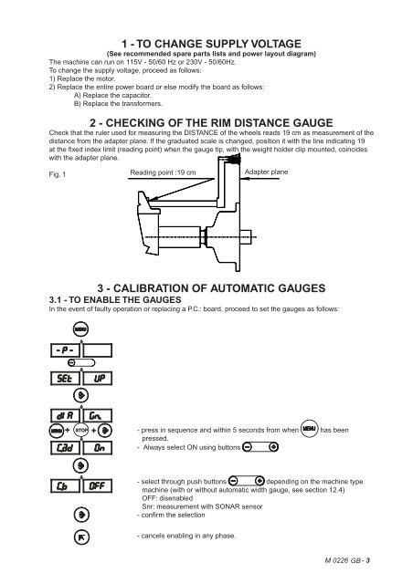
1 - TO CHANGE SUPPLY VOLTAGE(See recommended spare parts lists and power layout diagram)The machine can run on 115V - 50/60 Hz or 230V - 50/60Hz.To change the supply voltage, proceed as follows:1) Replace the motor.2) Replace the entire power board or else modify the board as follows:A) Replace the capacitor.B) Replace the transformers.2 - CHECKING OF THE RIM DISTANCE GAUGECheck that the ruler used for measuring the DISTANCE of the wheels reads 19 cm as measurement of thedistance from the adapter plane. If the graduated scale is changed, position it with the line indicating 19at the fi xed index limit (reading point) when the gauge tip, with the weight holder clip mounted, coincideswith the adapter plane.Fig. 1 Reading point :19 cm Adapter plane3 - CALIBRATION OF AUTOMATIC GAUGES3.1 - TO ENABLE THE GAUGESIn the event of faulty operation or replacing a P.C.: board, proceed to set the gauges as follows:+ STOP +- press in sequence and within 5 seconds from when has beenpressed.- Always select ON using buttons- select through push buttons depending on the machine typemachine (with or without automatic width gauge, see section 12.4)OFF: disenabledSnr: measurement with SONAR sensor- confi rm the selection- cancels enabling in any phase.M 0226 GB - 3
- Page 1 and 2: Instructions for useIContentsPage1
- Page 3 and 4: 1- GENERAL1.1 - GENERAL SAFETY RECO
- Page 5 and 6: 3 - COMMISSIONING3.1 - ANCHORINGThe
- Page 7 and 8: SE2-Dismounting360°abcdConee- Qua-
- Page 9 and 10: 4.3 - AUTOMATIC DISTANCE AND DIAMET
- Page 11 and 12: OPERATION FUNCTIONS MENUEccentricit
- Page 13 and 14: 5.2.1.1 - “AUTOMATIC WIDTH” OPT
- Page 15 and 16: 5.3 - RECALCULATION OF THE UNBALANC
- Page 17 and 18: RESULTS UNBALANCE MEASUREMENTFig. 1
- Page 19 and 20: 5.4.4 - ALU AND STATIC MODESFrom th
- Page 21 and 22: 6.1 - SELF-DIAGNOSTICS6 - SET UPDIS
- Page 23 and 24: 6.3 SCREEN SAVERIt is possible to e
- Page 25 and 26: 6.3.3 - WIDTH GAUGE (OPTIONAL)Set w
- Page 27 and 28: 10 - RECOMMENDED SPARE PARTS LIST(F
- Page 29 and 30: 111923 10456737811108111Guarnizione
- Page 31 and 32: C 72 (A) - C 72SE (B)E-0226-C72-GB.
- Page 33 and 34: D0112-111 2 3 4 5 6 7 68 9 6 7 10 1
- Page 35 and 36: D0140-1.1-BP1.1-BPONLY BN. CODE DAT
- Page 37 and 38: D0112-33123 4121110945687N. CODE DA
- Page 39 and 40: D0186-44171511716152431413111256879
- Page 41 and 42: D0186-6611B25 2624231211A105 6 7222
- Page 43: D0186-8-428-42N. CODE DATA N. CODE
- Page 48 and 49: 3.2 - CALIBRATION OF THE DISTANCE P
- Page 50 and 51: 5 - TROUBLE SHOOTING SEQUENCETests
- Page 52 and 53: 6 - POWER SUPPLY LAYOUT DIAGRAMFig.
- Page 54 and 55: 8 - TO CHECK MACHINE CALIBRATION1)
- Page 56: M 0226 - 12 GB
1 - TO CHANGE SUPPLY VOLTAGE(See recommended spare parts lists and power layout diagram)The machine can run on 115V - 50/60 Hz or 230V - 50/60Hz.To change the supply voltage, proceed as follows:1) Replace the motor.2) Replace the entire power board or else modify the board as follows:A) Replace the capacitor.B) Replace the transformers.2 - CHECKING OF THE RIM DISTANCE GAUGECheck that the ruler used for measuring the DISTANCE of the wheels reads 19 cm as measurement of thedistance from the adapter plane. If the graduated scale is changed, position it with the line indicating 19at the fi xed index limit (reading point) when the gauge tip, with the weight holder clip mounted, coincideswith the adapter plane.Fig. 1 Reading point :19 cm Adapter plane3 - CALIBRATION OF AUTOMATIC GAUGES3.1 - TO ENABLE THE GAUGESIn the event of faulty operation or replacing a P.C.: board, proceed to set the gauges as follows:+ STOP +- press in sequence and within 5 seconds from when has beenpressed.- Always select ON using buttons- select through push buttons depending on the machine typemachine (with or without automatic width gauge, see section 12.4)OFF: disenabledSnr: measurement with SONAR sensor- confi rm the selection- cancels enabling in any phase.M 0226 GB - 3


