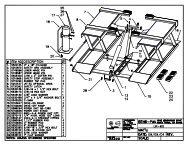
CEMB C72 Parts List
CEMB C72 Parts List
CEMB C72 Parts List

You also want an ePaper? Increase the reach of your titles
YUMPU automatically turns print PDFs into web optimized ePapers that Google loves.
Instructions for useIContentsPage1 - GENERAL......................................................................................................................................................................31.1 - GENERAL SAFETY REGULATIONS ...............................................................................................................31.1.1 - STANDARD SAFETY DEVICES ..........................................................................................................31.2 - FIELD OF APPLICATION .................................................................................................................................31.3 - OVERALL DIMENSIONS .................................................................................................................................31.4- SPECIFICATION ..............................................................................................................................................42 - HANDLING, HOISTING ...............................................................................................................................................43 - START-UP ....................................................................................................................................................................53.1 - ANCHORING ....................................................................................................................................................53.2 - ELECTRICAL CONNECTION . .........................................................................................................................53.3 - PNEUMATIC CONNECTION (Versions SE )......................................................................................................53.4 - EXTRA SAFETY DEVICES (VERSION SE ) ....................................................................................................53.5 - ADAPTER MOUNTING ....................................................................................................................................53.5 - WHEEL GUARD ASSEMBLY AND ADJUSTMENT ...........................................................................................83.7 - SPACER WD ......................................................................................................................................................84 - CONTROLS AND COMPONENTS .............................................................................................................................84.1 - BRAKE PEDAL...................................................................................................................................................84.2 - PNEUMATIC LOCKING PEDAL (Version P) ......................................................................................................84.3 - AUTOMATIC RIM DISTANCE AND DIAMETER GAUGE ..................................................................................94.4 - AUTOMATIC WIDTH GAUGE (OPTIONAL) ......................................................................................................94.5 - AUTOMATIC WHEEL POSITIONING ................................................................................................................94.6 - CONTROL PANEL AND DISPLAY .................................................................................................................104.6.1 CONTROL OF THE FUNCTIONS MENU ..............................................................................................115 - INDICATIONS AND USE OF THE WHEEL BALANCER ..........................................................................................125.1 - DOUBLE OPERATOR PROGRAM ..................................................................................................................125.2 - PRESETTING OF WHEEL DIMENSIONS ....................................................................................................125.2.1 - AUTOMATIC PRESETTING ...............................................................................................................125.2.1.1 - “AUTOMATIC WIDTH” OPTION ........................................................................................................135.2.1.2 - WHEEL ALU-S ..................................................................................................................................135.2.2 - MANUAL PRESETTTING ..................................................................................................................145.3 - RECALCULATION OF THE UNBALANCE .....................................................................................................155.4 - RESULT OF MEASUREMENT .......................................................................................................................155.4.1 - INDICATION OF EXACT CORRECTION POSITION IN ALU-S ........................................................155.4.2 - RESOLUTION OF THE UNBALANCE (SPLIT) ..................................................................................165.4.3 - UNBALANCE OPTIMIZATION ...........................................................................................................185.4.4 - ALU AND STATIC MODES .................................................................................................................195.4.5 -AUTOMATIC MINIMIZATION OF STATIC UNBALANCE ......................................................................195.5 - ECCENTRICTY MEASUREMENT (OPTION)..................................................................................................206 - SET UP ......................................................................................................................................................................216.1 - SELF-DIAGNOSTICS .....................................................................................................................................216.2 - SELF-CALIBRATION ......................................................................................................................................226.3 - SCREEN SAVER.............................................................................................................................................236.4 - AUTOMATIC GAUGES ..................................................................................................................................246.4.1 - RIM DISTANCE GAUGE ....................................................................................................................246.4.2 - DIAMETER GAUGE ...........................................................................................................................246.4.3 - WIDTH GAUGE (OPTIONAL)) .............................................................................................................256.5 - AMBIENT TEMPERATURE ..............................................................................................................................257 - ERRORS ....................................................................................................................................................................267.1 - INCONSISTENT UNBALANCE READINGS ..................................................................................................268 - ROUTINE MAINTENANCE ........................................................................................................................................268.1 - TO REPLACE THE FUSES ..............................................................................................................................269 - RECOMMENDED SPARE PARTS LIST......................................................................................................................27I 0226 GB - 1
I 0226 GB - 2
1- GENERAL1.1 - GENERAL SAFETY RECOMMENDATIONS- The balancing machine should only be used by duly authorized and trained personnel.- The balancing machine should not be used for purposes other than those described in theinstruction manual.- Under no way should the balancing machine be modified except for those modifications madeexplicitly by the manufacturer.- Never remove the safety devices. Any work on the machine should only be carried out by dulyauthorized specialist personnel.- Do not use strong jets of compressed air for cleaning.- Use alcohol to clean plastic panels or shelves (AVOID LIQUIDS CONTAINING SOLVENTS).- Before starting the wheel balancing cycle, make sure that the wheel is securely locked on theadapter.- The machine operator should not wear clothes with flapping edges. Make sure that unauthorizedpersonnel do not approach the balancing machine during the work cycle.- Avoid placing counterweights or other objects in the base which could impair the correctoperation of the balancing machine.1.1.1 - STANDARD SAFETY DEVICES- STOP push button for stopping the wheel under emergency conditions.- The safety guard of high impact plastic is with shape and size designed to prevent risk ofcounterweights from flying out in any direction except towards the floor.- A microswitch prevents starting the machine if the guard is not lowered and stops the wheelwhenever the guard is raised.1.2 - FIELD OF APPLICATIONThe machine is designed for balancing car or motorcycle wheels weighing less than 65 kg. It can beoperated within a temperature range of 0° to + 45°C.It can measure the geometric radial run-out of the wheels (optional)1.3 - OVERALL DIMENSIONS (42" Protection)Fig. 1169013151865I 0226 GB - 3
1.4 - SPECIFICATIONSingle phase power supply................................ 115 - 230 V 50-60 HzProtection class ................................................ IP 54Max. power consumption................................... 1100 WBalancing speed approx. ................................... 180 min -1Cycle time for average wheel (14 Kg).............. (14 Kg) 6 secondsBalancing accuracy ........................................... 0,1 grammiPosition resolution ............................................. ± 1.4 °Average noise level............................................ < 70 dB(A)Distance rim - machine...................................... 0 - 280 mm (400 mm can be preset)Larghezza cerchione impostabile ..................... 1.5” ÷ 20” or 40 ÷ 510 mmDiameter setting range ...................................... 10” ÷ 24” or 265 ÷ 615 mmTotal wheel diameter within guard ..................... 1067 (42”)Total wheel width within guard........................... 500 (42”)Max. wheel weight ............................................. 65 Kg.Min/max. compressed air pressure.................... 7 ÷ 10 Kg/cm 2 approx. 0.7 to 1 Mpa; approx. 7 to 10 BAR;.........................................................................................approx. 100 to 145 PSI.2 - HANDLING AND HOISTINGFig. 2Fig. 2aNB: DO NOT HOIST THE MACHINE USING DIFFERENT GRIPSI 0226 GB - 4
3 - COMMISSIONING3.1 - ANCHORINGThe machine can be operated on any fl at non-resilient fl oor.Make sure that the machine rests solely on the three support points provided (fi g. 2a).It is advisable to secure the system to the ground using the specific feet (see Figure 2a) in theevent of continual use with wheels weighing over 35 Kg.3.2 - ELECTRICAL CONNECTIONThe machine is supplied with a single phase mains cable plus earth (ground).The supply voltage (and mains frequency) is given on the machine nameplate. It may NOT be changed.Connection to the mains should always be made by expert personnel.The machine should not be started up without proper earth (ground) connection.Connection to the mains should be through a slow acting safety switch rated at 4A (230V) or 10A (115V) .3.3 - PNEUMATIC CONNECTION (Versions SE)For operation of the spindle with pneumatic locking (costant thrust air spring) connect the balancing to thecompressed air main. The connection fi tting is located at the back of the machine. At least 7 Kg/cm 2 (~ 0.7MPa; ~ 7 BAR; ~ 100 PSI) pressure is needed for correct operation of the release device.3.4 - EXTRA SAFETY DEVICES (VERSION SE)- Wheel always locked even when there is pressure failure during the balancing cycle.- Always actuate the unlocking control pedal with the machine stationary in order to avoid stressand abnormal wear on the adapter.3.5 - ADAPTER MOUNTINGThe balancing machine is supplied complete with cone adapter for fastening wheels with central bore.Other optional fl anges can be mounted once the terminal part is removed (also see enclosed brochures)N.B. Carefully clean the coupling surfaces before performing any operationa) DISMOUNTING THREADED END PIECEFig. 3ABa) Back-off screw B and remove threaded end-piece A.b) Fit the new adapterI 0226 GB - 5
1-2 mmSE2-Mounting0 mmabcdefgSE2_ 0140
SE2-Dismounting360°abcdConee- Qua-ndo possibile, centrare le ruote con cono dall'interno (vedi disegno).- Evitare di usare il manicotto RL con cerchi di ferro.- Whenever possible, centre the wheels with the cone from the inside (see the drawing).- Avoid using the RL sleeve with metal rims.- Lorsque c’est possible, centrer les roues avec le cône de l’intérieur (voir dessin).- Eviter d’utiliser le manchon RL avec les jantes en fer.- Wenn möglich, die Räder mit Konus von Innen heraus zentrieren (siehe Zeichnung).- Bei Eisenfelgen die Verwendung der Muffe RL vermeiden.- Siempre que sea posible, centrar las ruedas con cono desde dentro (véase dibujo).- Evitar usar el manguito RL con llantas de hierro.SE2_ 0140
3.6 - GUARD MOUNTING AND ADJUSTMENTa) Fasten the components to the base as illustrated in specifi c exploded view.b) The position of the wheel guard when closed can be adjusted with relative screw accessible at the back.Correct position is the one which keeps the tube exactly horizontal with wheel guard closed.c) Check that the microswitch is held down when the guard is closed.d) Adjust the angular position of microswitch control.3.7 - SPACER WDWhen balancing very wide wheels (9”), there is not enough space to turn the distance gauge. To withdrawthe wheel from the machine side, fi t spacer WD on the adapter body and secure it with the standard issuenuts. When centring the wheel with the cone on the inside, fi t the spacer DC to obtain spring thrust.Fig.4DCWDSpringCone4.1 - BRAKE PEDALFig.54 - CONTROLS AND COMPONENTSThis pedal allows the operator to hold thewheel when fi tting the counterweights.It must not be actuated during themeasuring cycle.4.2 - PNEUMATIC LOCKING PEDAL (Version P)Fig.6This pedal allows releasing the devicefastening the wheel on the adapter.Do not actuate this pedal during themachine cycle and/or when adaptersother than the standard coneadapter are mounted.The pedal has two stable positions:top, wheel unclamped; bottom,wheel clampedI 0226 GB - 8
4.3 - AUTOMATIC DISTANCE AND DIAMETER GAUGEThis gauge allows measurement of the distance of the wheel from the machine and the wheel diameter atthe point of application of the counterweight.It also allows correct positioning of the counterweights on the inside by using the specifi c function whichallows reading the position used for the measurement within the rim.The gauge can only be used with the counterweight pincers mounted.4.4 - AUTOMATIC WIDTH GAUGE (OPTIONAL)Width gauging is through a SONAR device which measures the distance of the wheel without mechanicalcontact, merely by closing the guard and each time a valid measurement has been made with gaugeDISTANCE AND DIAMETER GAUGE.4.5 - AUTOMATIC WHEEL POSITIONINGAt the end of the spin, the wheel is positioned according to the unbalance on the outside or elseaccording to the static unbalance (when selected).Precision is ± 20° for wheels up to 25 kg. in weight. Positioning is automatically disenabled for wheelsof less than 13” in diameter.I 0226 GB - 9
CONTROL PANEL AND DISPLAYFig. 75761315834910141817161920211122122324251 2261-2 Digital readouts, AMOUNT OF UNBALANCE, inside/outside3-4 Digital readouts, POSITION OF UNBALANCE, inside/outside5 Indicators, correction mode selected6 User Indicators7 Weight correction position indicators8 Distance gauge position indicator9 SPLIT “ON” indicator10 OPT “ON” indicator11 Measurements in mm indicator12 ALUS “ON” indicator13 Push button, operator selection14 Push button, SPLIT (unbalance resolution)15 Emergency push button16 Push button, cycle start17 OPT Pushbutton (unbalance optimisation)18 HOME Pushbutton (terminate function)19 Push button, FUNCTIONS MENU20 Inch/mm dimensions selection pushbutton21 Push button, eccentricity measurement selection (optional)22 Push button, menu selection confi rmation23 Push button, selection of mode of correction24 Position repeater push button25 Push button, unbalance reading < 5 g (25 oz)26 Push buttons, manual DISTANCE/DIAMETER/WIDTH settingNote:- Only use the fi ngers to press the push buttons. Never use the counterweight pincers or otherpointed objects.- In case of audible alarm connected (see par. OPERATION FUNCTIONS MENU), anypush button operation sounds with a “beep” alarm.I 0226 GB - 10
OPERATION FUNCTIONS MENUEccentricitymeasurementon/off (option)guard on/offon/off start fromguard closingapproximates1-5g or .1-.25 ozon/off beepsignalCONFIRMCONFIRMCONFIRMCONFIRMCONFIRMSee SELF-DIAGNOSTICS chapterSee SELF-CALIBRATION chapter****g/oz unit ofunbal.measurementScreen-saverduration(in minutes)Calibration of automatic RIM DISTANCE gaugeCalibration of automatic DIAMETER gaugeCalibration of automatic WIDTH gauge (optional)Ambienttemperature(in °C)CONFIRMCONFIRMCONFIRMRETURNS TO MEASUREMENT SCREEN*N.B. If such indications fail to appear, contact Technical ServiceI 0226 GB- 11
5 - INDICATIONS AND USE OF THE WHEEL BALANCER5.1 - DOUBLE OPERATOR PROGRAMThis program allows memorizing the dimensions of two types of wheels. Thus two operators can worksimultaneously on two different cars using the same balancing machine. The system memorizes twoprograms with various preset dimensions.1 - Press to select operator (1 or 2). Selection is confi rmed by panel-mounted LED.2 - Enter the dimensions (see PRESETTING OF WHEEL DIMENSIONS)3 - carry out the balancing as usualWith program 1 or 2 is called for subsequent balancing operations without having to newly enterthe dimensions.5.2 - PRESETTING OF WHEEL DIMENSIONS5.2.1 - AUTOMATIC PRESETTING- Standard wheels (calibration necessary also for modes ALU 1, 2, 3, 4 Static)Fig. 8 DISTANCE + DIAMETERMove the gauge tip into contact against the rim keeping it inposition for at least 2 seconds.N.B. Measurement is the same in position A or B. Always usethe round part of the contact tip.Pos. APos. BIndication of gauge in movementIndication of dimensions acquired.N.B.: When the beep signal is enabled (see section CONTROLOF THE FUNCTIONS MENU), reaching of the dimensions isaccompanied by a “beep”Return the gauge to position 0. If automatic WIDTH readout isdisenabled (see GAUGE ENABLE), the system automatically goes to theWIDTH position.The system automatically switches to WIDTH position- The nominal width is normally stampedon the rim; if not, proceed to measuredimension “b” with the calibre gauge(supplied as standard).I 0226 GB - 12
5.2.1.1 - “AUTOMATIC WIDTH” OPTIONIf WIDTH measurement with sonar is enabled, the machine is set for the acquisition of this value:Fig. 9The LT script on the LH matrix display indicates that LIGHT TRUCK wheel measurement is set (largedimension wheels such as off-road, trucks or wheels which protrude signifi cantly from the rim).This function can be enabled/disenabled by pressing push button prior to the measurement, whichis then performed by closing the guard; once completely closed and if “automatic START on guard closure”is enabled, the launch will be made for unbalance measurement. If automatic START is disenabled, oncethe guard is closed the display will show the width value measured.5.2.1.2 - WHEEL ALU-S(correction from inside for two balancing planes with direct calibration):Fig. 10After measurement for inside F1 as shown, again remove the gauge in order to memorize the data for theoutside FE; keep the position for at least 2 seconds. The measurement can be made either in the positionshown in Fig. 8/Pos.A or in Fig. 8/Pos.B.Manual presetting is possible by using the push buttons as for detailed hereunder.I 0226 GB - 13
5.2.2 - MANUAL PRESETTING- Standard wheelsFig. 11ba- Press to read -a- on the display- Preset distance “a” of the inside of the wheel from the machine (in mm).d- Press to select -d-- Preset the nominal diameter “d” indicated on the tyre.- Press to select -b-- Preset the nominal width which is normally stamped on the rim; if not,measure dimension “b” with the calibre gauge (supplied as standard).- Wheel ALU-S- Measure the dimensions as shown in thefollowing diagram.Fig. 12dIdEaaIaEPRESETTING:Pressto select the measurement to setN.B.: If dE is not preset, default value dE = 0.8 dlDuring setting-up of values -b- -d- -dI- -dE- press button(on machine start-up, the dimensions are in INCHES).to switch measurement from inches to mmI 0226 GB - 14
5.3 - RECALCULATION OF THE UNBALANCEPressafter new setting of the measurement5.4 - RESULT OF MEASUREMENTFig. 13Inside correctionOutside correctionAfter performing a balancing spin, the amounts of unbalance are shown on the digital readouts.When the matrix display is ON, this indicates the correct angular wheel position for fi ttingcounterweights. (12 o’clock position). When the beep signal is enabled (see section CONTROLOF THE FUNCTIONS MENU), this is activated when the wheel reaches the correction position.If the unbalance is less than the threshold selected, is displayed instead of the unbalance, with itis possible to read the values below the threshold chosen gram by gram.If the static unbalance is greater than 30 gr., the OPT Led fl ashes to suggest an unbalance optimisationoperation. (see UNBALANCE OPTIMIZATION)5.4.1 - INDICATION OF EXACT CORRECTION POSITION IN ALU-SIn correction mode ALU-S it is possible to cancel approximations in the mountingof the counterweights by proceeding as follows:- press- Insert the correct weight on the relative seat on the weight holder pincers- Remove the gauge when the display shows:to indicate that the gauge should be pulled further outto indicate that the gauge should be returned to rest positionThe left display gives the indications for reaching the position regarding the inside, while the right displaythat of the outsideThe position of the gauge is also indicated by the position repeater Led (8).Positionreached onthe internalsideFig. 14I 0226 GB- 15
Fig. 15Positionreachedon theexternal side- Bring the wheel into correct angular position.- Move the gauge until the display corresponding to the selected correction plane shows the unbalancevalue again.- Rotate the rim until the correct weight lies against the rim.- The fact that the weight application position is no longer vertical (fi g. 16) is offset automatically.N.B. : It is not possible to put automatically the correction weight in the Fig.8/Pos.B position; alwaysrotate the rim in Fig.5/Pos.AFig. 165.4.2 - RESOLUTION OF THE UNBALANCE (SPLIT)SPLIT only has meaning in the case of static unbalance or ALU-S on outside. It serves for hiding anystick-on unbalance correction weights behind the rim spokes.PRESETTING:Perform a balancing spin ( )Fig. 17- Place any spoke in the 12 o’clock position- set the number of spokes- / confi rm the settings enabling unbalancesplitI 0226 GB - 16
RESULTS UNBALANCE MEASUREMENTFig. 183015Unbalance breakdown NOTin position3015Correction position 13015Correction position 2To return to normal unbalance display, perform a new spin by pressing or else push button .I 0226 GB - 17
5.4.3 - UNBALANCE OPTIMIZATION- This function serves to reduce the amount of weight to be added in order to balance the wheel.- It is suitable for static unbalance exceeding 30 g.- It improves the residual eccentricity of the tyre.Unbalance already measuredNo previous unbalancemeasurementunbalance measurement- Mark with chalk a reference point on theadapter and rim.- With the aid of a tyre remover, turn the tyre onthe rim by 180°.- Refi t the wheel with the reference markcoinciding between rim and adapter.TYREPOSITION- RH display: percentage reduction- LH display: actual static unbalance which canbe reduced by rotation.RIMPOSITION- Mark the two positions of the rim and tyre,and turn the tyre on the rim until the positionscorrespond in order to obtain the optimizationon the display.RETURN TO MEASUREMENT SCREENI 0226 GB - 18
5.4.4 - ALU AND STATIC MODESFrom the Measurement screen, press button to select the type required. The 5-LED displays showthe position where to apply the weights. If a spin has already been performed, the processor automaticallyrecalculates, for each change of mode, the amounts of unbalance according to the new calculation.Fig. 19DYNAMICBalancing steel or light alloy wheel rims byapplying clamp weights on the edge of the wheel rim.STATICOALU - SThe static mode is necessary for motorcycle wheels orwhen it is not possible to place the counterweights onboth sides of the rim.Balancing of light alloy rims with application of adhesiveweights in positions inside the rim (user settable).ALU - 1Balancing of light alloy rims with application of adhesiveweights on the rim shoulders.12/13 mmresting surfaceALU - 2Balancing of light alloy rims with hidden application of theouter adhesive weight. Outer weight position is fi xed.ALU - 3Combined application: clip-on weight inside and hiddenadhesive weight on outside (Mercedes). Outer weightposition is the same as ALU-2.ALU - 4Combined application: adhesive weight outside andclip-on weight inside.5.4.5 - AUTOMATIC MINIMIZATION OF STATIC UNBALANCEInitial unbalancesx dxg gphase shift 50Possible approximationssxgdxgsxgdxgsx4 g 3 g residual static1 g 6 gresidual static residual static residual staticWith conventionalwheel balancerThis program is designed to improve the quality of balancing without any mental effort or loss of time by the operator.In fact by using the normal commercially available weights, with pitch of 5 in every 5 g, and by applying the twocounterweights which a conventional wheel balancer rounds to the nearest value, there could be a residual staticunbalance of up to 4 g. The damage of such approximation is emphasized by the fact that static unbalance iscause of most of disturbances on the vehicle. This new function, resident in the machine, automatically indicates theoptimum entity of the weights to be applied by approximating them in an “intelligent” way according to their positionin order to minimize residual static unbalance.gdxChoice with minimumstatic residualgsxgdxgI 0226 GB - 19
5.5 ECCENTRICTY MEASUREMENT (OPTION)The figures are significantly enlarged to highlight the external surface of the tyre and the wheel rotation axis.Fig. A highlights the total Peak-Peak eccentricity measurement, defi ned as the maximum radial offsetof the surface of the tyre.Fig. AFig. BFig. B highlights the 1st harmonic eccentricitymeasurement, i.e. the eccentricity of the rim“refl ecting” the shape of the tyre, to calculatethe averages values of local offset of the tyrefrom roundness.It is evident that the P-P measurement isnormally higher than the 1st harmonicmeasurement. Tyre manufacturers usuallyprovide two different tolerances for the twotypes of eccentricity.At the end of a balancing spin, eccentricity measurement of the tyre can be performed automaticallyusing the SONAR sensor placed on the guard. To enable measurement at the end of every spin, seethe section MENU FUNCTION CONTROL.Fig.20EMSThe value of the fi rst harmonic with the relative phaseis displayed.EMSHold down thevalue.button to display the Peak-PeakRelease the button to return to the display of thefi rst harmonic value.BACK TO MEASUREMENT WINDOWN.B.: The eccentricity measurement is valid up to max. tyre Ø of 1000 mm.I 0226 GB - 20
6.1 - SELF-DIAGNOSTICS6 - SET UPDISPLAY TESTAll displays, readouts and LED’s should light up1The RH display indicates thecurrent position of the wheel, withnumbers from 0 to 127When the wheel is turned in theunbalance measurement rotationdirection, the down arrows mustappear.The central LED for the wheel (1)must come on ONLY ONCE perrotation at position 0.- Test parameter- Displays values of rim DISTANCEsensor- Displays values of DIAMETERsensor- Displys values of WIDTH sensor(optional)- Displays eccentricity measurementsensor values (RUN OUT - option)END OF SELF-DIAGNOSTICSCANCELS SELF-DIAGNOSTICSIN ANY PHASEI 0226 GB - 21
6.2 - SELF-CALIBRATIONFor machine self-calibration proceed as follows:- Fit a medium-sized metal wheel on the shaft. Example: 6” x 14” (± 1”)- Preset the exact dimensions of the wheel mounted.CAUTION!!Presetting of incorrect dimensions would mean that the machine is not correctlycalibrated, therefore all subsequent measurements will be incorrect until a new selfcalibrationis performed with the correct dimensions!- Perform a spin under normal conditions.- Add 100 g (3.5 oz) on the outside in any angular position.- Shift the 100 g. weight from the outside to the inside keepingthe same angular position.- Shift the 100 g. weight to the 12 o’clock position.END OF SELF-CALIBRATIONCANCELS SELF-CALIBRATION IN ANY PHASEI 0226 GB - 22
6.3 SCREEN SAVERIt is possible to enable a screen saver function which temporarily replaces the data displayed with movingsymbols. This function acts when the balancing system is not used for the time period defi ned in therelative set-up:Modify time expressed in minutes.CONFIRMIf the value is set to 0, the screen saver is automatically disenabled.The screen saver is not active in the balancing machine set-up menu.To return to normal balancing machine function, simply press any button or move the wheel or thedistance gauge.I 0226 GB - 23
6.3 - AUTOMATIC GAUGES6.3.1 - RIM DISTANCE GAUGE- Shift the distance gauge to position , keeping it quite still,press- Move the gauge to position , pressCORRECT CALIBRATION- Return the gauge to rest position- The wheel balancer is ready for operationN.B.: In the event of errors or faulty operation, the writing appears on the display : shiftthe gauge to position and repeat the calibration operation exactly as described above. If theerror persists, contact the Technical Service Department. In the event of incorrect input in the rimdistance gauge calibration function, pressto cancel it.6.3.2 - DIAMETER GAUGE- Currently preset diameter.- Set the diameter with which to calibrate the machine (10÷18”)with- Press- Move the gauge tip into measuring position (Fig. 8/Pos.A) andkeeping it still, pressCORRECT CALIBRATION- Return the gauge to rest position- The wheel balancer is ready for operationIn the event of incorrect input in the rim distance gauge calibration function, pressto cancel it.I 0226 GB - 24
6.3.3 - WIDTH GAUGE (OPTIONAL)Set withthe distance in mm between theSONAR sensor and the distance gauge clamp in pos. 0.-0In the event of incorrect input in the width gauge calibration function, press .6.5 AMBIENT TEMPERATUREWhen automatic width measurement or eccentricity measurement are enabled, the ambient temperaturemust be set to ensure correct calibration of the sonar sensors.Set the average ambient temperature for thelocation of the balancing machine.CONFIRMI 0226 GB - 25
7 - ERRORSDuring machine operation, various causes of faulty operation could occur. If detected by themicroprocessor, they appear on the display as follows:ERRORMEANING1 No rotation signal. Could be caused by faulty position transducer, or somethingpreventing the wheel from turning.2 During the measurement spins, wheel speed had dropped below 60 r.p.m. Checkencoder functioning (see SELF-DIAGNOSTICS) and repeat the launch.3 Unbalance too high.4 Rotation in opposite direction.5 Guard open before start of spin.7 Fault in reading the machine calibration parameters. Repeat the self-calibration.8 Fault in reading the machine calibration parameters. Repeat the self-calibration.9 General fault in memory of the machine calibration parameters. ContactTechnical Service Department.10 Measured width too small. Repeat the automatic width measurement making surethat the preset distance value is correct.11 Speed too high during unbalance measurement spins.12/13/14 Diffi culty in reading the analog signal. Check encoder functioning (see SELF-DIAGNOSTICS). Contact Technical Service Department.15/17 Inside/outside analog signal too high. Contact Technical Service.16/18 Inside/outside analog signal too low. Contact Technical Service.7.1 - INCONSISTENT UNBALANCE READINGSSometimes after balancing a wheel and removing it from the balancing machine, it is found that, uponmounting it on the machine again, the wheel is not balanced.This does not depend on incorrect indication of the machine, but only on faulty mounting of the wheelon the adapter; i.e. in the two mountings, the wheel has assumed a different position with respect to thebalancing machine shaft centre line. If the wheel has been mounted on the adapter with screws, it couldbe possible that the screws have not been correctly tightened, i.e. crosswise one by one, or else (as oftenoccurs) holes have been drilled on the wheel with too wide tolerances.Small errors, up to 10 grams (0.4 oz) are to be considered normal in wheels locked by a cone; the error isnormally greater for wheels fastened with screws or studs.If, after balancing, the wheel is found to be still out-of-balance when refi tted on the vehicle, this could bedue to the unbalance of the car brake drum or very often due to the holes for the screws on the rim anddrum sometimes drilled with too wide tolerances. In such case a readjustment could be advisable usingthe balancing machine with the wheel mounted (For example, see our models L36, L38/2).8 - ROUTINE MAINTENANCESwitch off the machine from the mains before carrying out any operation.8.1 - TO REPLACE THE FUSESThe power supply board, accessible from the rear by removing the rear cover, is fi tted with safety fuses(see Exploded Drawings). If fuses require replacement, use ones of the same current rating.If the fault persists, contact the Technical Service Department.NONE OF THE OTHER MACHINE PARTS REQUIRE MAINTENANCE.I 0226 GB - 26
10 - RECOMMENDED SPARE PARTS LIST(For further details, see exploded drawings)CODEDESCRIPTION020600503 Bearing 6005-2Z dia. 25/47/12181198630 Spring 19863P080077007 Rigid belt Poly V - TB2 - 770 - 7 Vee’s67M38954CPosition pick-up board with cable182245870 Spring, brake lever 24587P05PR50728LEXAN panel182185750 Spring, rim distance gauge67M48208APower board with 2 relays/ 2 sonar681002000 Fuses DM 5x20 - 2A511242101 Oscillating switch 16A86SC50842Computer board86SB38988Cable, automatic rim distance gauge86SB36493Cable, automatic diameter gauge86SB50843Width sonar (optional)86SB38585Cable with microswitch for 42” protectionSPECIAL PARTS FOR 230V MACHINES501054213 Single phase motor BIMA 230V/50-60 Hz -0.18Kw 63/B3 - 4p.86SZ50844Complete power board611000314 Braking transformer 30VA 230 - 0/50568001458 Capacitor 14MF 450 V FASTON screw M8611035188 Power transformer 40VASPECIAL PARTS FOR 115V MACHINES502054114 Single phase motor BIMA 115V/50-60Hz- 0.18Kw - 63/ B3 - 4p86SZ50845Complete power board611000313 Braking transformer 30VA 115-0/25568002557 Capacitor 25MF 450V FASTON screw M8611035187 Power transformer 40VASPECIAL PARTS FOR SPINDLE SE020600702 Bearing 6007 - LLB/2AV1 dia. 35/62x14 Front.020600703 Bearing 6007 - 2Z dia. 35/62x14 Rear.18FP29329Air spring 115 kg. stroke 75 mm.16FB42177Coil valve18FB42639Spring, pneumatic pedalSPECIAL PARTS FOR EMS SONAR (OPTION)86SB50847Ems sonarI 0226 GB - 27
I 0226 GB - 28
111923 10456737811108111Guarnizione GFV4Raccordo EREL 8/4 (CAMOZZI S6520-8-1/4)9 1 Nipplo S2500 1/4Cilindro spec. s.e. Ö90 corsa 8016FP29330P170001408. 172100845 WAIRCOM17400020116FP29330WAIRCOMCAMOZZIFEMAS7 2 Guarnizione GFV8170001309 WAIRCOM61Raccordo EROL 8/8 (CAMOZZI 6610-8-1/8")172100887WAIRCOM5 1 Raccordo ERPC 1/84 1 Valvola modulare a spola172078092 WAIRCOM16FB42177 BUTLER31.5mTubo calibrato 8/61790062082 1 Micro reg. di pressione M004-R00164000014CAMOZZI1 1 Innesto RG4/12/9. 173010901 WAIRCOMPOS. PEZZI DENOMINAZIONENß DISEGNOCODICEMARCAne vieta la riproduzione e la comunicazione a terziEsso dovra' essere restituito a fine consultazioneLa Societa' tutela i propri diritti a norma di legge<strong>CEMB</strong>C62SE (D)03/02/01Spostato MicReg interno bas.(BISSI)Sirico06/12/991:1GRUPPO :CODICE GRUPPO :ASSIEME46AS38449Schema pneumatico16SP43470P.........M O D I F I C H EPressione d'utilizzo7-10 Kg/cmparete post. BasamentoQuesto disegno e' proprieta' esclusiva della <strong>CEMB</strong> cheCLIENTE :MACCHINA :CDSOST. ILSOST. DALRIC. DALDISEGNATODATASCALE<strong>CEMB</strong>Costruzioni Elettro MeccanicheIng. Buzzi & C. - S.p.A.DENOMINAZIONE :DIS. N.2ABPneumatic circuit diagramSpI 0226 GB - 29
I 0226 GB - 30
C 72 (A) - C 72SE (B)E-0226-<strong>C72</strong>-GB.PDFD0112-1 0109-1 1 MANDRINO SHAFT ASSEMBLYD0140-1-BP 0140-1-BP 1-BP MANDRINO PNEUMATICO PNEUMATIC SHAFT ASSEMBLYD0140-1.1-BP 0140-1.1-BP 1.1-BP TERMINALE “SE2” SHAFT END PIECE “SE2”MOTORE+DATORE DI FASE+MOTOR+POSITION PICK-UP+D0111-2 0162-2 2TRASDUTTORI PIEZOPIEZO TRANSDUCERD0112-3 0112-3 3 FRENO BRAKED0111-3-BP 0111-3-BP 3-BP FRENO+PEDALE BP BRAKE+BP PEDALD0186-4 0186-4 4 BASAMENTO CASINGD0186-5 0186-5 5 BASAMENTO CASINGCALIBRO AUTOMATICO:“DISTANCE + 22” DIAMETER”D0186-6 0186-6 6“DISTANZA + DIAMETRO 22”AUTOMATIC GAUGED0186-7 0186-7 7 POTENZA POWER UNITD0186-8-42 0186-8-42 8-42 PROTEZIONE RUOTA 42” 42”WHEEL GUARDD0186-10 0186-10 10 SONAR EMS EMS SONAR* Particolari reperibili in commercio * <strong>Parts</strong> on the market
C 72 (A) - C 72SE (B)E-0226-<strong>C72</strong>-D.PDFD0112-1 0109-1 1 DORN BROCHE MANDRILD0140-1-BP 0140-1-BP 1-BP PNEUMATISCHER DORN BROCHE PNEUMATIQUE MANDRIL NEUMATICOD0140-1.1-BP 0140-1.1-BP 1.1-BP WELLE ENDSTÜCK “SE2” PIECE TERMINAL “SE2” POUR ARBRE PARTE TERMINAL EYE “SE2”D0111-2 0162-2 2MOTOR+PHASENGEBER+ MOTEUR+DONNEUR DE PHASE+ MOTOR+CAPTADOR DE FASE+PIEZOGEBER TRANSDUCTEURS PIEZO TRANSDUCTORES PIEZOELECTRICOSD0112-3 0112-3 3 BREMSE FREIN FRENOD0111-3-BP 0111-3-BP 3-BP BREMSE+BP PEDAL FREIN+PEDALE BP FRENO+PEDAL BPD0186-4 0186-4 4 SOCKEL BASE BASED0186-5 0186-5 5 SOCKEL BASE BASED0186-6 0186-6 6AUT. MESSLEHRE: “ABSTAND CALIBRE AUTOMATIQUE: CALIBRE AUTOMATICO:UND 22” DURCHMESSER” “DISTANCE + DIAMETRE 22” “DISTANCIA + DIAMETRO 22”D0186-7 0186-7 7 NETZEINHEIT PUISSANCE POTENCIAD0186-8-42 0186-8-42 8-42 RADSCHUTZVERKLEIDUNG 42” PROTECTION ROUE 42” PROTECCION RUEDA 42”D0186-10 0186-10 10 SONAR EMS SONAR EMS SONAR EMS* Handelsübliche Teile * Pièces se trouvant dans le commerce * Piezas que se encuentran en el mercado
D0112-111 2 3 4 5 6 7 68 9 6 7 10 11 1222212019 18 17 16 15 14 13N. CODE DATA N. CODE DATA N. CODE DATA1 311225120 *11 04FM4063020 326035009 *2 325046010 *12 42FM3693121 325046008 *3 326035011 *13 114008002 *22 312120093 *4 42FM3909314 312120137 *5 04FM3862115 325047011 *6 341000025 *16 940103565 Ø 36 standard7 020600503 *16 42FM51717 Ø 36 L = 1858 42FM3692917 344200118 *9 04001010118 42FP4105610 342000047 *19 1811986300109-1
D0140-1-BP1-BPN. CODE DATA N. CODE DATA N. CODE DATA1 172078092 *15 319216068 *28 04FP406292 170001309 *16 42FP3693729 0400101013 42FP2962017 342000062 *30 200000024 *4 16FP2933018 341000035 *31 311220037 *5 345081609 * 19F 020600702 *32 42FB331836 42FP3693319R 020600703 *33 325035005 *7 344200080 *20 312120093 *34 321232005 *8 42FP36892 Ø 36 21 326035009 *35 04FM386218 42FP41006 Ø 40 22 42FP3689536 335310095 *9 18FP2932923 42FP36893 Ø 36 37 331220103 *10 42FP2961723 42FP41008 Ø 40 38 311220051 *11 42FP3112124 18119863039 42FP3270012 325046008 *25 42FP4105640 325035008 *13 311220093 *26 344200118 *41 321232008 *14 42FP3111727 42FP3693842 172100887 *0140-1-BP
D0140-1.1-BP1.1-BPONLY BN. CODE DATA N. CODE DATA N. CODE DATA1 46FP53579 Ø 36 A-B 5 42FP53639 Ø 40 B 9 42FP53637 Ø 40 B1 46FP53636 Ø 40 A-B 6 42FP52740 Ø 36 A-B2 342000028 Ø 36 A-B* 6 42FP52762 Ø 40 A-B2 342000032 Ø 40 A-B* 7 18FP527443 18FP52745 Ø 36 A-B 8 42FP52739 Ø 36/40 A3 18FP52763 Ø 40 A-B 8 42FP53581 Ø 36 B4 032000120 *8 42FP53638 Ø 40 B5 42FP52736 Ø 36 A 9 42FP52732 Ø 36 A5 42FP53600 Ø 36 B 9 42FP53580 Ø 36 B5 42FP52761 Ø 40 A 9 42FP52758 Ø 40 A0140-1.1-BP
D0111-2212154326 71189101314 15910281918171621202324FG27202126ED2021202522D=WHITEE=YELLOWF=YELLOWG=BLUE24232021N. CODE DATA N. CODE DATA N. CODE DATA1 86SD38732 BP 10 325035006 *20 325035010 *1 86SD4061211 321232006 *21 321212010 *2 42061063912 501054213 230V/50-60 Hz 22 9407012323 42SD37841 BP 12 502054114 115V/50-60 Hz 23 3451225153 42SD3622813 348016015 *24 326035011 *4 314231018 *14 07102400925 1051101655 67M38954C15 325035007 *26 1051147446 325035003 *16 311220036 *27 9407012337 321232003 *17 325046004 *28 42FG423918 311220072 *18 325035004 *9 325046006 *19 0800770070162-2
D0112-33123 4121110945687N. CODE DATA N. CODE DATA N. CODE DATA1 21702143411 42FB319572 325035004 *12 1822458703 311220034 *4 337110015 *5 42FB319586 4209230937 321233008 *8 325035010 *9 42092939210 337110010 *0112-3
D0111-3-BP3-BP123426252423225 6 7 821201991018151110171615141312N. CODE DATA N. CODE DATA N. CODE DATA1 21702143411 42FB4218621 16FB421772 325035004 *12 325035010 *22 179006208 *3 311220034 *13 321233008 *23 4209293924 337110015 *14 341000015 *24 337110010 *5 331220039 *15 325035005 *25 42FB319576 335310085 *16 311220051 *26 1822458707 42FB4218817 42FB421878 42FB4218518 312120052 *9 18FB4263919 42FB4218310 341000018 *20 321232005 *0111-3-BP
D0186-4417151171615243141311125687910N. CODE DATA N. CODE DATA N. CODE DATA1 213005623 *10 42BV507812 14FB5035311 3011000073 317224070 *12 200000016 *4 14FB5035513 1402129605 173010901 * BP 14 1051329006 170001408 * BP 15 325035006 *7 164000014 * BP 16 325046006 *8 174000201 * BP 17 312120072 *9 172100845 * BP10 42BV50772 BP0186-4
D0186-55117 5 3 6 4 2 8 9 10112N. CODE DATA N. CODE DATA N. CODE DATA1 86PR5084111 42FB507212 321232003 *12 320233006 *3 86SC508424 527034980 *5 42PR507276 315231015 *7 05PR507288 329007663 *9 329004434 *10 14FB503560186-5
D0186-6611B25 2624231211A105 6 7222721172892019181617151413N. CODE DATA N. CODE DATA N. CODE DATA2 42FB4985813 18218575023 2170212835 04014290214 52300001824 42FC402786 42FC3318915 21702596525 325035003 *7 321232003 *16 86SB3898826 314231018 *8 21FC4731517 58802031227 86SB364939 312120071 *18 319216034 *10 314231023 *19 325046006 *11A42FC4206320 311220071 *11B 94001406721 42FC40276 *12 319216065 *22 344200060 *0186-6
D0186-771221 208 91841789107 63519N. CODE DATA N. CODE DATA N. CODE DATA1 51124210110 611035188 40VA (230V)2 42023015710 611035187 40VA (115V)3 86SZ50844 230V 17 611000314 30VA (230V)3 86SZ50845 115V 17 611000313 30VA (115V)4 42SZ5054018 568001458 14MF (230V)5 527006175 *18 568002557 25MF(115V)6 67M48208A19 526003246 *7 681002000 *20 321232006 *8 325035004 *21 325047006 *9 317232034 *0186-7
D0186-8-428-42N. CODE DATA N. CODE DATA N. CODE DATA1 319216068 *12 86SB508432 42FW3298913 325035008 *3 21701927514 325046008 *4 311220096 *19 86SB385855 321232008 *20 5171405156 14FW4121421 314231042 *8 314931069 *22 325035003 *9 18FW4439110 42FW5053311 314931018 *0186-8-42
Special maintenanceMContentsPage1 - TO CHANGE SUPPLY VOLTAGE ..................................................................................................................................32 - CHECKING OF THE RIM DISTANCE GAUGE..............................................................................................................33 - CALIBRATION OF AUTOMATIC GAUGES ..................................................................................................................33.1 - TO ENABLE THE GAUGES ...............................................................................................................................33.2 - CALIBRATION OF THE DISTANCE POTENTIOMETER ..................................................................................43.3 - CALIBRATION OF THE DIAMETER POTENTIOMETER ..................................................................................43.4 - CALIBRATION WIDTH SONAR AND EMS (OPTIONAL)...................................................................................44 - ASSEMBLY OF THE PIEZO MEASURERS ..................................................................................................................55 - LOGIC TROUBLE SHOOTING SEQUENCE.................................................................................................................66 - POWER SUPPLY LAYOUT DIAGRAM..........................................................................................................................87 - TO REPLACE THE POWER BOARD.............................................................................................................................98 - TO CHECK MACHINE CALIBRATION........................................................................................................................109 - WHEEL MEASUREMENT AND PRESETTING ON THE BALANCING MACHINE ....................................................1010 - HOW TO CHECK FUNCTIONING AND ACCURACY ...............................................................................................11M 0226 GB - 1
M 0226 - 2 GB
1 - TO CHANGE SUPPLY VOLTAGE(See recommended spare parts lists and power layout diagram)The machine can run on 115V - 50/60 Hz or 230V - 50/60Hz.To change the supply voltage, proceed as follows:1) Replace the motor.2) Replace the entire power board or else modify the board as follows:A) Replace the capacitor.B) Replace the transformers.2 - CHECKING OF THE RIM DISTANCE GAUGECheck that the ruler used for measuring the DISTANCE of the wheels reads 19 cm as measurement of thedistance from the adapter plane. If the graduated scale is changed, position it with the line indicating 19at the fi xed index limit (reading point) when the gauge tip, with the weight holder clip mounted, coincideswith the adapter plane.Fig. 1 Reading point :19 cm Adapter plane3 - CALIBRATION OF AUTOMATIC GAUGES3.1 - TO ENABLE THE GAUGESIn the event of faulty operation or replacing a P.C.: board, proceed to set the gauges as follows:+ STOP +- press in sequence and within 5 seconds from when has beenpressed.- Always select ON using buttons- select through push buttons depending on the machine typemachine (with or without automatic width gauge, see section 12.4)OFF: disenabledSnr: measurement with SONAR sensor- confi rm the selection- cancels enabling in any phase.M 0226 GB - 3
3.2 - CALIBRATION OF THE DISTANCE POTENTIOMETER- Remove the weight shelf and refi t the tip on the gauge rod.- Back-off the screws fastening the pulley on the potentiometer shaft.- Select on the FUNCTIONS MENU (CONTROL OF THE FUNCTIONS MENU) → SET UP → AUTODIAGNOSTIC(SELF-DIAGNOSTICS)- Scroll until the wording (diS) appears on the left display while a number appears on the rightdisplay, which varies when the distance gauge is moved and represents a reference for calibrating thepotentiometer.- With the gauge fully retracted, turn the potentiometer shaft keeping the pulley still until a numberbetween 50 and 100 is read.- Decrease by two numbers, then retighten the screws to secure the pulley on the shaft.Carry out the DISTANCE GAUGE SET UP (RIM DISTANCE GAUGE);3.3 - CALIBRATION OF THE DIAMETER POTENTIOMETER- After CALIBRATION OF THE DISTANCE POTENTIOMETER press- The wording [dIA] appears on the left display, a number appears on the right display, which varies whenthe gauge is turned and represents a reference for calibrating the potentiometer.- Remove the diameter gauge from the gauge rod after backing off relative screw.- Slightly pull out the gauge rod and rest its stop on the machine shaft in external position near the base.- Turn the potentiometer shaft until a number between 50 and 100 is read, then place it back in itscorrect work position.- Lock the potentiometer with relative set screw- Carry out the DIAMETER GAUGE SET UP (DIAMETER GAUGE)3.4 - CALIBRATION WIDTH SONAR AND EMS (OPTIONAL)- After DIAMETER POTENTIOMETER CALIBRATION press .- Place a fl at surface at least 12 cm from the width Sonar and check that there are variations in thenumber displayed.- If on control, after having performed calibration, a measurement inaccuracy is found greater than 1/2”,repeat the calibration modifying the distance value between the tyre and the sensor (tolerance ± 20 mmfrom the measurement found manually) until a correct width value is obtained.- Press again and repeat the operation for the EMS sonar, checking the number on the display.M 0226 - 4 GB
4 - ASSEMBLY OF THE PIEZO MEASURERSProblems of excessive compensation and out-of-phase sometimes depends on a fault in the piezomeasurers.To replace them, proceed as follows:1. Remove the weight shelf.2. Remove nuts 1 and 2 with relative cup springs and washers.3. Back-off screws 3, 4 and 5 then disassemble the various parts.4. Reassemble the various parts without tightening the nuts being careful to follow the correct sequence.N.B. Mount the piezo units in accordance with the position of the coloured wires shown in the drawing.5. Keeping the spindle perfectly aligned, tighten nut 5 with a spanner, and nuts 3 and 4 by hand (by halfa turn with the spanner if necessary).6. Refi t the washers, cup springs and nuts 1 and 2. Tighten the nuts fully in order to fully regain theelasticity of the cup springs, then loosen them by half a turn. This will automatically ensure correctpreloading on the piezo (a torque wrench can be used set to 400 kg. cm.).7. Cover the piezo units with a generous layer of silicone.(N.B.: For correct operation, insulation of the piezo crystals should be grater than 50 Mohm).8. Reassemble the various parts.9. Again carry out the automatic calibration.Fig. 2YellowblueyellowwhiteM 0226 GB - 5
5 - TROUBLE SHOOTING SEQUENCETests on power 2 relay/2 sonar1) Transformer output on CN32) Fuses FS1 - FS2 - FS3 - FS43) SONAR power supplyFig. 317 VCA07 VCA15 VCA015 VCA876543217 VCA215 VCA15 VCA7 VCA3-12 VDC253+12 VDC41-12 VDC253+12 VDC41M 0226 GB - 6
Tests on computer board1) 7 - 0 - 7 VCA on CN12)Machine SELF TESTS (WHEEL BALANCING MACHINE SELF-TEST)- encoder- distance gauge- diameter gauge- sonar width and sonar EMS (65,000 infi nite, should decrease when it refl ects)Fig. 412 1CN17 0 7 VCAM 0226 GB - 7
6 - POWER SUPPLY LAYOUT DIAGRAMFig. 5MSONARWIDTHSONAREMSWHEELGUARDCOMPUTERCN8CN7CN2CN6CN1FS1-2AFS2-2ACN3707150FS3-2AFS4-2A15CN5M11234567C75ONLY3241M 0226 GB - 8
7 - TO REPLACE POWER BOARDFig. 6MSONARWIDTHSONAREMSWHEELGUARDCOMPUTERCN8CN7CN2CN6CN1FS1-2AFS2-2ACN3707150FS3-2AFS4-2A15CN5M11234567C75ONLY3241M 0226 GB - 9
8 - TO CHECK MACHINE CALIBRATION1) Mount an average size iron wheel and carefully preset the Distance / Diameter / Width.2) Make 10 consecutive measuring spins and determine the repeatability error (normally ± 1 g.; acceptable ± 2 g.).3) Balance the wheel as best as possible.4) Apply 100 g. on the outside; the following should be true:F.E. = 100 ± 5 F.I. ≤ 5 gr Weight F.E. = position = 6 o’clock5) Remove the 100 g. weight from the outside and apply it to the Inside; the following should be true:F.I. = 100 ± 5 F.E. ≤ 5 gr Weight F.I. = position = o’clock6) If the values are out of tolerance, proceed to a self-calibration and repeat points 3), 4), 5).9 - WHEEL MEASUREMENT AND PRESETTING ON THEBALANCING MACHINEThe ever increasing need for more accurate calibration and use of the ALU functions means that it isimportant to establish how to measure the rims and how the balancing machine interprets the presetdata. Hence a description is now given of how to modify the preset dimensions automatically in orderto obtain the distances of the correction planes which are defi ned as through planes for the centres ofgravity of the corrective weights.Consider a typical rim: size “l”, given as width by the rim manufacturer, differs from the measurementof the distance between the correction planes for the rim thickness and physical dimensions of thecounterweight, whose centre of gravity is located at distance “h” from the resting point of the rim edge.The balancing machine automatically corrects the measurement preset by adding 2 x h = 6 mm to themeasurement. Measurement “b” made with the gauge is generally more accurate even if very similar to themeasurement “l” known to the rim user. The two measurements differ only by the thickness of the sheetmetal, usually about 2 mm per side. Such insignifi cant distance means that an accurate calibration canbe obtained regardless of whether the inner rim with “l” or outer width “b” is preset. It is a good rule toadd ¼ inch to the value given by the manufacturer. As regards the ALU functions, the machine performsthe following approximations in addition to the systematic correction regarding the centre of gravity ofthe counterweight as seen above.I12/13 mmresting piano appoggio surfaceIEEALU 1a = a preset +¾”b = b preset -1 ½”d = d preset - 1”ALU 2a = a preset +¾”b = distance of adapter surface -½” -adl = d preset - 1”dE = d preset - 2 ½”ALU 3a = a presetb = distance of adapter surface -½” -adl = d presetdE = d preset - 2 ½”N.B.:I = INSIDEE = OUTSIDEM 0226 GB - 10IdIaIaEdEEALU 4a = a presetb = b preset -¾”dl = d presetdE = d preset - 1”ALU - Sa = aI preset -7 mmb = aE - aIdl = d presetdE = dI . 0.8
10 - HOW TO CHECK FUNCTIONING AND ACCURACYFurther to some notices informing us of defects and unaccuracies not clearly traceable, we are explaininghereunder the procedure how to check functioning and accuracy to help us to detect problems.FIRST CHECKS. Accurate wiping of adapter and cones. Spring cover sliding. Shaft end blockingCHECKING SENSOR (from Self-test page) – see SELF-DIAGNOSTICS -. POTENZIOMETER DIST.= between 50 and 1000 by pulling out distance gauge completely. POTENZIOMETER DIA= between 50 and 1000 by opening diameter gauge wide. Sonar 1= (w/monitor) Width. From 65000 to 3000 by approaching a target. Range: 40 ÷ 11 cm. Sonar 2= (w/monitor) eccentricity. From 65000 to 3000 by approaching a target. Range: 40 ÷ 11 cmGAUGE CALIBRATION (use an average size iron wheel i,.e. 14” x 6” ± 1”)- see AUTOMATIC GAUGES -. DIST./DIAM./LA WIDTH:Calibrate gauges and check accuracy. it is necessary to set the correct distance rate to obtain an accuratewidth measure.Tolerances: DIST.= 5 mm DIAM.= ± ½” WIDTH= ± ¼”. SONAR WIDTH (balancers with monitor):1. Mount an average size iron rim, detect accurately width measure by using a traditional gauge orby selecting the nominal measure written on the rim and adding ¼”2. Make the operations described in WIDTH GAUGE (OPTIONAL).Make sure calibration is correct. Amend distance rate (+/- 20 mm) if necessary until getting an accuratewidth indication. Any time distance rate is changed, repeat calibration.CALIBRATION (see SELF-CALIBRATION). Use the same wheel as for gauge calibration. Set accurate measures, in manual mode if necessary. Make self-calibrationCHECKING MACHINE CALIBRATION1. Make 10 spins without loosening the wheel and detect MAX oscillationsF.I. (Inner side)= F.E. (Outer side)= (tolerance ± 2)2. Put 100 gr. on FE fi rst and then on FI using an accurately balanced wheel) Detect ratesF.I.= F.E.= POS.E.= F.I.= F.E.= POS.I=(tolerance 3%)CHECKING THE ADAPTERTurn a fi ne balanced wheel upside down (180°) and detect unbalance ratesERR.MAX =This check-out in particular must be made with a sample wheel whose max unbalance errors due tocentering are well known (generally lower than 10 gr. for iron wheels).M 0226 GB - 11
M 0226 - 12 GB