development of atmospheric pressure plasma jet in air - Kathmandu ...
development of atmospheric pressure plasma jet in air - Kathmandu ...
development of atmospheric pressure plasma jet in air - Kathmandu ...

Create successful ePaper yourself
Turn your PDF publications into a flip-book with our unique Google optimized e-Paper software.
KATHMANDU UNIVERSITY JOURNAL OF SCIENCE, ENGINEERING AND TECHNOLOGYVOL. 8, No. I, FEBRUARY, 2012, pp 15-22DEVELOPMENT OF ATMOSPHERIC PRESSURE PLASMA JET IN AIR1, 2R. B. Tyata*, 1 D. P. Subedi, 1 A. Shrestha, 1 D. Baral1 Department <strong>of</strong> Natural Science, <strong>Kathmandu</strong> University, Dhulikhel, Nepal2 Department <strong>of</strong> Electrical, Khwopa College <strong>of</strong> Eng<strong>in</strong>eer<strong>in</strong>g, Libali-2, Bhaktapur, Nepal*Correspond<strong>in</strong>g address: rbtyata@yahoo.comReceived 17 October, 2011; Revised 29 December, 2011ABSTRACTIn this paper, an <strong>atmospheric</strong> <strong>pressure</strong> <strong>plasma</strong> <strong>jet</strong> (APPJ) <strong>in</strong> <strong>air</strong> that is expected to be usefulfor polymer surface modification has been reported. The <strong>plasma</strong> <strong>jet</strong> was produced byapply<strong>in</strong>g (10 30) kHz, (0 20) kV AC source. The electrical and optical measurementshave also been reported. The use <strong>of</strong> solenoid as an external electrode has been found to bemore effective <strong>in</strong> boost<strong>in</strong>g the <strong>jet</strong> to a distance up to 30 mm even with a small flow rate <strong>of</strong><strong>air</strong>. The characteristic <strong>of</strong> the proposed APPJ was <strong>in</strong>vestigated by measur<strong>in</strong>g the effect <strong>of</strong>treatment on a PE film on the <strong>jet</strong> for different exposition time and distance from the nozzle. Ithas been confirmed that the <strong>jet</strong> can modify polymer film with a work distance <strong>of</strong> over 25mm.This <strong>plasma</strong> <strong>jet</strong> can be useful for the treatment and clean<strong>in</strong>g <strong>of</strong> objects hav<strong>in</strong>g large structuresand could be used <strong>in</strong> wider areas <strong>of</strong> application.Keywords: APPJ, PE film, AirINTRODUCTIONIn the last one decade, the <strong>atmospheric</strong> <strong>pressure</strong> cold <strong>plasma</strong> research is highly <strong>in</strong>creased dueto its important applications <strong>in</strong> various fields. These types <strong>of</strong> <strong>plasma</strong> are non-equilibriumsystems, where electron temperature is much higher than ion temperature. Atmospheric<strong>plasma</strong> cold <strong>plasma</strong> treatment <strong>of</strong> materials is a promis<strong>in</strong>g technology that is simpler to set-up,easier and economical to operate and does not require vacuum equipments.Among the various applications <strong>of</strong> the <strong>atmospheric</strong> <strong>pressure</strong> cold <strong>plasma</strong>s, there aresterilizations <strong>of</strong> liv<strong>in</strong>g tissue without damage and blood coagulation [1], modulation <strong>of</strong> cellattachment [2], biological and chemical decontam<strong>in</strong>ation [3-5], water decontam<strong>in</strong>ations andpollution control [6-7], nanotechnologies [8], surface clean<strong>in</strong>g, etch<strong>in</strong>g, th<strong>in</strong> film deposition,surface modification and material process<strong>in</strong>g [9-13].In an <strong>atmospheric</strong> <strong>pressure</strong> <strong>plasma</strong> <strong>jet</strong>, <strong>plasma</strong> constituents are expelled through an orifice <strong>of</strong>a long nozzle along a gas flow. This type <strong>of</strong> <strong>plasma</strong> can be operated under high gas flow rateand can flow out <strong>plasma</strong> <strong>in</strong> space. In 2003, Toshifuji et al. reported a relatively cold arc<strong>plasma</strong><strong>jet</strong> produced under <strong>atmospheric</strong> <strong>pressure</strong> hav<strong>in</strong>g potential application for surfacemodification [14]. Quite recently, Takemura et al. developed an <strong>atmospheric</strong> <strong>pressure</strong> <strong>plasma</strong><strong>jet</strong> with long flame. In this work it has been reported that the flame <strong>of</strong> N 2 <strong>plasma</strong> <strong>jet</strong> has beenelongated to about 200mm length. It has been confirmed that the long flame <strong>plasma</strong> <strong>jet</strong> canmodify polymer film with a work distance <strong>of</strong> over 200 mm [15]. Similarly, Choi et al. haverecently reported a double layered <strong>atmospheric</strong> <strong>pressure</strong> which is expected to improve15
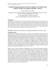
KATHMANDU UNIVERSITY JOURNAL OF SCIENCE, ENGINEERING AND TECHNOLOGYVOL. 8, No. I, FEBRUARY, 2012, pp 15-22conventional s<strong>in</strong>gle layered <strong>atmospheric</strong> <strong>pressure</strong> <strong>plasma</strong> <strong>jet</strong>s [16]. In the same l<strong>in</strong>e, theobjective <strong>of</strong> the present work is to develop the conventional APPJ and use <strong>of</strong> <strong>air</strong> to producethe <strong>plasma</strong> <strong>jet</strong> for polymer surface modification.EXPERIMENTAL DESCRIPTIONSchematic diagram <strong>of</strong> the <strong>plasma</strong> <strong>jet</strong> is depicted <strong>in</strong> Fig. 1. A copper needle electrode <strong>of</strong>diameter 1mm was placed <strong>in</strong>side a glass tube <strong>of</strong> <strong>in</strong>ner diameter 4 mm and outer diameter 6mm. The outer electrode was an alum<strong>in</strong>um foil wrapped around the outer surface <strong>of</strong> the glasstube. The clearance around the central electrode was 1.5 mm. The electrodes were connectedto a high voltage (0-20 kV) power supply operat<strong>in</strong>g at a frequency <strong>of</strong> 10-30 kHz. Air waspassed through the <strong>in</strong>ter-electrode space us<strong>in</strong>g an <strong>air</strong> pump. The temperature <strong>of</strong> the <strong>jet</strong> wasmeasured by an IR thermometer. The gas temperature was <strong>in</strong> the range 26-28ºC which showsthat the <strong>plasma</strong> is non-thermal <strong>in</strong> nature. In order to evaluate the efficiency <strong>of</strong> the presentAPPJ, hydrophilicity test was performed. The contact angles are measured from the sessiledrops <strong>of</strong> water made on the surface <strong>of</strong> PE films treated at different distances from the nozzle<strong>of</strong> the <strong>jet</strong> for different exposure times. Each contact angle presented <strong>in</strong> this paper is anaverage <strong>of</strong> at least 4 measurements made on different place <strong>of</strong> the film.Digital OscilloscopePC. DAQ.Voltage ProbeOESAirCurrent ProbeAPPJHigh FrequencyPower SupplyFig.1 Experimental setup for arc <strong>plasma</strong> <strong>jet</strong> generation and characterizationWork<strong>in</strong>g gas is fed <strong>in</strong> to the annular space between two electrodes and <strong>air</strong> flows l<strong>in</strong>early at30L/m<strong>in</strong>. After pass<strong>in</strong>g <strong>air</strong> <strong>in</strong> the <strong>in</strong>ner volume <strong>of</strong> the reactor, <strong>plasma</strong> <strong>jet</strong> is spread out thenozzle with long frame. The <strong>in</strong>put power has been ma<strong>in</strong>ta<strong>in</strong> constant. The treatment is carriedout by expos<strong>in</strong>g the samples <strong>in</strong> the <strong>plasma</strong> <strong>jet</strong> flame with the help <strong>of</strong> rotat<strong>in</strong>g belt attached <strong>in</strong>the electric motor hav<strong>in</strong>g 20rpm as shown <strong>in</strong> Fig. 2.16
KATHMANDU UNIVERSITY JOURNAL OF SCIENCE, ENGINEERING AND TECHNOLOGYVOL. 8, No. I, FEBRUARY, 2012, pp 15-22Fig. 2 Schematic diagram <strong>of</strong> PE treatment and show<strong>in</strong>g the low temperature nature <strong>of</strong>the <strong>plasma</strong> <strong>jet</strong> be<strong>in</strong>g exposed to f<strong>in</strong>ger.CONTACT ANGLE ANALYSISThe most common method <strong>of</strong> quantify<strong>in</strong>g wett<strong>in</strong>g is the contact angle measurement.Furthermore, the measurement <strong>of</strong> contact angle on a solid surface is the most practical way toobta<strong>in</strong> <strong>in</strong>formation about surface energy: solid-vapor and solid-liquid surface tension. Thecontact angle is def<strong>in</strong>ed as the angle between the solid surface and the tangent to thesurface <strong>of</strong> the drop at the po<strong>in</strong>t <strong>of</strong> contact <strong>of</strong> the two as shown <strong>in</strong> Fig. 3.lvVaporsvLiquidslSolidFig. 3 Schematic diagram <strong>of</strong> the contact angle and <strong>in</strong>terfacial tensions <strong>of</strong> the threesurfaces at the three-phase boundaryThe contact angle <strong>of</strong> a liquid drop on a solid substrate is related to <strong>in</strong>terfacial tensions, whichis given by Young´s equation as.lvcos [1]svslwhere, sv is the surface free energy <strong>of</strong> the solid substrate, sl is the <strong>in</strong>terfacial tensionbetween the solid and the liquid and 1v is the surface tension <strong>of</strong> the liquid.This equation shows that a perfect wett<strong>in</strong>g i.e. cos tend<strong>in</strong>g to unity is favored by a highenergy surface solid, low <strong>in</strong>terfacial free energy and low liquid surface free energy.17
Contact Angle ( )KATHMANDU UNIVERSITY JOURNAL OF SCIENCE, ENGINEERING AND TECHNOLOGYVOL. 8, No. I, FEBRUARY, 2012, pp 15-22The contact angle <strong>of</strong> a liquid on solid is strongly <strong>in</strong>fluenced by a number <strong>of</strong> factors such assurface roughness, chemical heterogeneity, sorption layers, molecular orientation andswell<strong>in</strong>g. These effects have to be considered when contact angle measurements are used tocalculate the solid surface tension.In this study the contact angle <strong>of</strong> drops with the surface <strong>of</strong> the flat plate <strong>of</strong> PE was measuredus<strong>in</strong>g a rame'- hart Contact Angle Goniometer model 200. This unit is equipped withstandard s<strong>of</strong>tware to analyze the drop image for the calculation <strong>of</strong> surface energy. The system<strong>of</strong>fers a high level <strong>of</strong> computer aided precision <strong>in</strong> measur<strong>in</strong>g contact angle and therewithfacilitat<strong>in</strong>g the calculation <strong>of</strong> surface energy us<strong>in</strong>g different model equation.RESULTS AND DISCUSSIONEffect <strong>of</strong> treatment timeThe change <strong>in</strong> wettability <strong>of</strong> PE surface after 1-10s treatment times <strong>in</strong> APPJ <strong>in</strong> <strong>air</strong> wasquantitatively <strong>in</strong>vestigated by measur<strong>in</strong>g contact angles with water. The graphicalrepresentation between treatment time verses contact angle and images <strong>of</strong> water drop on thesurface <strong>of</strong> untreated and <strong>plasma</strong> treated PE surface and are depicted <strong>in</strong> Fig. 4. The watercontact angle on PE after treatment <strong>in</strong> APPJ at power 12 W is plotted as a function <strong>of</strong>treatment-time <strong>in</strong> Fig. 4. The contact angle decreased rapidly from the orig<strong>in</strong>al value <strong>of</strong> 104°to about 44° already after 5s <strong>of</strong> treatment.110100908070605040-0.5 0.0 0.5 1.0 1.5 2.0 2.5 3.0 3.5 4.0 4.5 5.0 5.5Treatment time (second)Fig. 4 Contact angle <strong>of</strong> water drop on PE film as a function <strong>of</strong>treatment time for RAPP. The distance from the nozzle was 5mm.Effect <strong>of</strong> distanceThe effect <strong>of</strong> distance <strong>of</strong> the nozzle <strong>of</strong> APPJ <strong>in</strong> PE treatment was clearly represented by theFig. 5. When the constant treatment time 10s was fixed, contact angle was <strong>in</strong>creased rapidlyfrom 20mm distance to PE substrate and <strong>in</strong>crease <strong>in</strong> contact angle was saturated from thedistance 30mm to PE substrate. This result shows that for the surface treatment <strong>of</strong> PEsubstrate suitable distance is less than 15mm form nozzle <strong>of</strong> APPJ to substrate.18
Current (mA)Voltage (kV)Contact angle [Deg.]KATHMANDU UNIVERSITY JOURNAL OF SCIENCE, ENGINEERING AND TECHNOLOGYVOL. 8, No. I, FEBRUARY, 2012, pp 15-2211010090807060500 5 10 15 20 25 30 35 40 45Distance from the Nozzle [mm]Fig. 5 Contact angle <strong>of</strong> water drop on PE film as a function <strong>of</strong> distance <strong>of</strong>the nozzle <strong>of</strong> RAPP <strong>in</strong> <strong>air</strong>. The treatment time was 10s.Current and voltage measurementFig. 6 shows the typical oscillographic waveform <strong>of</strong> the discharge current and voltage withcorrespond<strong>in</strong>g image <strong>of</strong> that discharge. This waveform gives measurement <strong>of</strong> current (I) andvoltage (V) <strong>in</strong> the present <strong>of</strong> steamers <strong>in</strong> APPJ. And, apparent power was calculated frommultiply<strong>in</strong>g voltage by current. In the traced waveform, we have seen current is more fluctuatedthan voltage with respect to time. And, current leads the voltage. That is why; <strong>in</strong> our high voltagepower supply capacitive load <strong>of</strong> APPJ is more than <strong>in</strong>ductive load <strong>in</strong> side the power supply.3CurrentVoltage12281400-1-4-2-8-3-12-120.0µ -80.0µ -40.0µ 0.0 40.0µ 80.0µ 120.0µTime (S)Fig. 6 Electrical measurements <strong>of</strong> APPJ19
Intensity (a.u.)297.5311.5315.6337.0353.6357.6370.9380.4375.4391.1399.7405.8KATHMANDU UNIVERSITY JOURNAL OF SCIENCE, ENGINEERING AND TECHNOLOGYVOL. 8, No. I, FEBRUARY, 2012, pp 15-22Optical spectrum analysesFig. 7 shows optical emission spectra (OES) measured from the <strong>plasma</strong> <strong>jet</strong> produced <strong>in</strong> <strong>air</strong>. AYov<strong>in</strong> Yvon optical emission spectrometer was used for the purpose. As seen from the graphthe OES was dom<strong>in</strong>ated by the second positive system (SPS) <strong>of</strong> N 2 (C 3 u –B 3 g). The firstnegative system (FNS) <strong>of</strong> N +2 (B 2 +u –X 2 +g) was also visible <strong>in</strong> violet range. No spectrafrom water vapor, oxygen and nitrogen oxide are observed with<strong>in</strong> the wavelength range (200-800 nm) due to sensitivity limitation <strong>of</strong> the monochrometer. Table 1 show that the significantspectral l<strong>in</strong>es and the correspond<strong>in</strong>g identified transition. The identified transitions werecalculated based upon vibrational constants [17]400003000020000100000250 300 350 400 450Wavelength (nm)Fig. 7 Optical emission spectra <strong>of</strong> APPJ <strong>in</strong> the wavelength range <strong>of</strong> 250-450 nmwhere the observation position was 10 mm from the nozzle.Table 1. Significant spectral l<strong>in</strong>es <strong>in</strong> <strong>atmospheric</strong> <strong>pressure</strong> <strong>air</strong> discharge.ExcitedspeciesWavelength(nm)Electronic transition VibrationaltransitionPeak(%)N 2 297.5 N 2 (C 3 u–B 3 g) 2–0 6.7N 2 311.5 N 2 (C 3 u –B 3 g) 3–2 15.4N 2 315.6 N 2 (C 3 u –B 3 g) 1–0 45.5N 2 337.0 N 2 (C 3 u –B 3 g) 0–0 100N 2 353.6 N 2 (C 3 u –B 3 g) 1–2 19.3N 2 357.6 N 2 (C 3 u –B 3 g) 0–1 53.9N 2 370.9 N 2 (C 3 u –B 3 g) 2–4 5.5N 2 375.4 N 2 (C 3 u –B 3 g) 1–3 15.6N 2 380.4 N 2 (C 3 u –B 3 g) 0–2 23.6N +2 391.1 N +2 (B 2 +u –X 2 +g ) 0–0 5.6N 2 399.7 N 2 (C 3 u –B 3 g) 1–4 6.7N 2 405.8 N 2 (C 3 u –B 3 g) 0–3 7.120
KATHMANDU UNIVERSITY JOURNAL OF SCIENCE, ENGINEERING AND TECHNOLOGYVOL. 8, No. I, FEBRUARY, 2012, pp 15-22CONCLUSIONAn <strong>atmospheric</strong> <strong>pressure</strong> <strong>plasma</strong> <strong>jet</strong> <strong>in</strong> <strong>air</strong> has been developed for PE surface modification.APPJ to improve the wettability <strong>of</strong> PE film has been tested successfully <strong>in</strong> this laboratory. Itwas found that the hydrophilicity <strong>of</strong> the PE film surface is l<strong>in</strong>early dependant on distanceeffect, while the effective exposure time can be as brief as 4 second. The characteristics <strong>of</strong>electrical and optical properties <strong>in</strong> our studies are similar to low temperature <strong>plasma</strong>.ACKNOWLEDGEMENTSThe authors would like to thank Pr<strong>of</strong>. C. S. Wong, Department <strong>of</strong> Physics, University <strong>of</strong>Malaya, Kuala Lumpur, Malaysia, for his valuable suggestions dur<strong>in</strong>g our work. We are alsothankful to Dr. Peter Ferer for his help <strong>in</strong> fabricat<strong>in</strong>g the power supply.REFERENCES[1] Fridman G, “Blood coagulation and liv<strong>in</strong>g tissue sterilization by float<strong>in</strong>g electrodedielectric barrier discharge <strong>in</strong> <strong>air</strong>”, Plasma chem. and <strong>plasma</strong> process., 26 (2006)425-442,.[2] St<strong>of</strong>fels E, Kieft I & Sladek R, “Superficial treatment <strong>of</strong> mammalian cells us<strong>in</strong>g<strong>plasma</strong> needle”, J. Phys. D. Appl. Phys., 36 (2003) 2908-2913,[3] Laroussi M, “Low temperature <strong>plasma</strong> based sterilization: Overview and state <strong>of</strong> theart”, Plasma Process. Polym., 2 (2005) 391-400,[4] Walsh J L & Kong M G, “Contrast<strong>in</strong>g characteristics <strong>of</strong> l<strong>in</strong>ear-field and cross-field<strong>atmospheric</strong> <strong>plasma</strong> <strong>jet</strong>s”, Appl. Phys. Lett., 93 (2008) 111 501[5] Lu X, Ye T, Y Cao, S Sun, Xiong Q, Tang Z, Xiong Z, Hu J, Jiang Z & Pan Y, „Therole <strong>of</strong> the various <strong>plasma</strong> agents <strong>in</strong> the <strong>in</strong>activation <strong>of</strong> bacteria”, J. Appl. Phys.,104(2008) 053 309[6] Bruggeman P & Leys C, “Non thermal <strong>plasma</strong>s <strong>in</strong> and <strong>in</strong> contact with liquids”, J.Phys. D: Appl. Phys., 42 (2009) 053 001[7] Kolb J F, Joshi R P, Xiao S & Schoenbach K H, “Stremears <strong>in</strong> water and otherdielectric liquids”, J. Phys. D. Appl. Phys., 41 (2008) 234 007[8] Gonzales-Aguilar J, Moreno M & Fulcheri L, “Carbon nanostructures production bygas-phase <strong>plasma</strong> processes at <strong>atmospheric</strong> <strong>pressure</strong>”, J. Phys. D: Appl .Phys., 40(2007) 2361-2374[9] Schutze A, Jeong J Y, Banayan S E, Park J, Selwyn G S & Hicks R F, “ The<strong>atmospheric</strong> <strong>pressure</strong> <strong>plasma</strong> Jet: A review and comparison to other <strong>plasma</strong> sources”,IEEE Trans. Plasma Sci., 26 (1998)1685-169421
KATHMANDU UNIVERSITY JOURNAL OF SCIENCE, ENGINEERING AND TECHNOLOGYVOL. 8, No. I, FEBRUARY, 2012, pp 15-22[10] Kunhardt E E, “Generation <strong>of</strong> large volume, <strong>atmospheric</strong>-<strong>pressure</strong> non equilibrium<strong>plasma</strong>s”, IEEE Trans. Plasma Sci., 28 (2000)189-200[11] Daun Y, Hung C & Yu Q S “Low temperature direct current golw discharges at<strong>atmospheric</strong> <strong>pressure</strong>”, IEEE Trans. Plasma Sci., 33 (2005) 328-329[12] Borcia G, Chiper A & Rusu I, “Us<strong>in</strong>g a He + N 2 dielectric barrier discharge for themodification <strong>of</strong> polymer surface properties”, Plasma sources Sci. Technol.,15 (2006)849-857[13] Benedict J, Forcke K, Yanguas-Gil A & Von Keudell A, “Atmospheric <strong>pressure</strong>micro <strong>plasma</strong> <strong>jet</strong> as a deposit<strong>in</strong>g tool”, J. Appl. Phys. 99 (2006) 112 303[14] Tioshifuji J, Katsumata T, Takikawa H, Sakakibara T & Shimizu I, “Cold arc- <strong>plasma</strong><strong>jet</strong> on the <strong>atmospheric</strong> <strong>pressure</strong> for surface modification", Surface and Coat<strong>in</strong>g Tech.,171 (2003) 302-306[15] Takemura Y, Kubota Y, Yamaguchi N & Hara T, “Development <strong>of</strong> atmospeheric<strong>plasma</strong> <strong>jet</strong> with long flame”, IEEE Trans. Plasma Sci., 26 (2009)1604-1606[16] Choi J, Matsuo K, Yoshida H, Namihira T, Katsuki S & Akiyama H, “Double layer<strong>atmospheric</strong> <strong>plasma</strong> <strong>jet</strong>”, Japanese J. <strong>of</strong> Appl. Phys., 48 (2009) 086 003[17] Laher R R & Gilmore F R, J. Phys. Chem. Ref. Data, 20 (1991) 68522