Code of Practice 1 Issue 2 Version 3.0 Superseded (CoP1 ... - Elexon
Code of Practice 1 Issue 2 Version 3.0 Superseded (CoP1 ... - Elexon
Code of Practice 1 Issue 2 Version 3.0 Superseded (CoP1 ... - Elexon

Create successful ePaper yourself
Turn your PDF publications into a flip-book with our unique Google optimized e-Paper software.
<strong>Code</strong> <strong>of</strong> <strong>Practice</strong> One<strong>Issue</strong> 2 (v<strong>3.0</strong>)_______________________________________________________________________________________CODE OF PRACTICE ONECODE OF PRACTICE FOR THE METERING OFCIRCUITS WITH A RATED CAPACITYEXCEEDING 100MVA FOR SETTLEMENTPURPOSES<strong>Issue</strong> 2<strong>Superseded</strong><strong>Version</strong> <strong>3.0</strong>DATE:______________________________________________________________________________________________________________Balancing and Settlement <strong>Code</strong> Page 1 <strong>of</strong> 36
<strong>Code</strong> <strong>of</strong> <strong>Practice</strong> One<strong>Issue</strong> 2 (v<strong>3.0</strong>)_______________________________________________________________________________________<strong>Code</strong> <strong>of</strong> <strong>Practice</strong> OneCODE OF PRACTICE FOR THE METERING OF CIRCUITS WITH A RATEDCAPACITY EXCEEDING 100MVA FOR SETTLEMENT PURPOSES.1. Reference is made to the Balancing and Settlement <strong>Code</strong> for the ElectricityIndustry in Great Britain, and in particular, to the definitions <strong>of</strong> “<strong>Code</strong> <strong>of</strong><strong>Practice</strong>” in Annex X-1 there<strong>of</strong>.2. This <strong>Code</strong> <strong>of</strong> <strong>Practice</strong> shall apply to Metering Systems comprising MeteringEquipment that are subject to the requirements <strong>of</strong> Section L <strong>of</strong> the Balancingand Settlement <strong>Code</strong>.3. This <strong>Code</strong> <strong>of</strong> <strong>Practice</strong> has been approved by the Panel.For and on behalf <strong>of</strong> the Panel.Intellectual Property Rights and Copyright - This document contains materials thecopyright and other intellectual property rights in which are vested in ELEXON Limited orwhich appear with the consent <strong>of</strong> the copyright owner. These materials are made availablefor you to review and to copy for the purposes <strong>of</strong> your establishment or operation <strong>of</strong> orparticipation in electricity trading arrangements under the Balancing and Settlement <strong>Code</strong>("BSC"). All other commercial use is prohibited. Unless you are a person having such aninterest in electricity trading under the BSC you are not permitted to view, download,modify, copy, distribute, transmit, store, reproduce or otherwise use, publish, licence,transfer, sell or create derivative works (in whatever format) from this document or anyinformation obtained from this document otherwise than for personal academic or othernon-commercial purposes. All copyright and other proprietary notices contained in theoriginal material must be retained on any copy that you make. All other rights <strong>of</strong> thecopyright owner not expressly dealt with above are reserved.<strong>Superseded</strong>Disclaimer - No representation, warranty or guarantee is made that the informationprovided is accurate, current or complete. Whilst care is taken in the collection andprovision <strong>of</strong> this information, ELEXON Limited will not be liable for any errors,omissions, misstatements or mistakes in any information or damages resulting from the use<strong>of</strong> this information or any decision made or action taken in reliance on this information.______________________________________________________________________________________________________________Balancing and Settlement <strong>Code</strong> Page 2 <strong>of</strong> 36
<strong>Code</strong> <strong>of</strong> <strong>Practice</strong> One<strong>Issue</strong> 2 (v<strong>3.0</strong>)_______________________________________________________________________________________AMENDMENT RECORDISSUE DATE VERSION CHANGES AUTHOR APPROVEDDraft 18/3/93 0.10 Recommended to PEC MSC1 15/4/93 1.00 Endorsed by PEC CoP WG1.00 Re-badging <strong>of</strong> <strong>Code</strong> <strong>of</strong>1 <strong>Code</strong>Date 1 implementation <strong>of</strong> theEffective<strong>Practice</strong> One for theBalancing and Settlement<strong>Code</strong>1 BETTA 2.0 BETTA 6.3 RebadgingEffectivechanges for the CVA FebDate05 Release2 23/02/06 <strong>3.0</strong> CP1051 changes for theFebruary 06 ReleaseBSCCoBSCCoBSCCoPanel16/11/00(Paper07/003)ISG/55/002<strong>Superseded</strong>1 “<strong>Code</strong> Effective Date” means the date <strong>of</strong> the Framework Agreement.______________________________________________________________________________________________________________Balancing and Settlement <strong>Code</strong> Page 3 <strong>of</strong> 36
<strong>Code</strong> <strong>of</strong> <strong>Practice</strong> One<strong>Issue</strong> 2 (v<strong>3.0</strong>)_______________________________________________________________________________________CONTENTSPage number5.6 Communication 245.6.1 Local Interrogation 265.6.2 Remote Interrogation 265.7 Sealing 276. ASSOCIATED FACILITIES 286.1 Interrogation Unit 286.2 Additional Features 287. ACCESS TO DATA 28APPENDIX A Defined Metering Points 29APPENDIX B Labelling <strong>of</strong> Meters for Import and Export 31APPENDIX C Fusing 34APPENDIX D Passwords 35APPENDIX E Guidance for the Use <strong>of</strong> Multi Core Metering Cables 36<strong>Superseded</strong>______________________________________________________________________________________________________________Balancing and Settlement <strong>Code</strong> Page 5 <strong>of</strong> 36
<strong>Code</strong> <strong>of</strong> <strong>Practice</strong> One<strong>Issue</strong> 2 (v<strong>3.0</strong>)_______________________________________________________________________________________FOREWORDThis <strong>Code</strong> <strong>of</strong> <strong>Practice</strong> defines the minimum requirements for the Metering Equipmentrequired for the measurement and recording <strong>of</strong> electricity transfers at DefinedMetering Points where the rated circuit capacity exceeds 100MVA.For the purpose <strong>of</strong> this <strong>Code</strong> <strong>of</strong> <strong>Practice</strong> the rated circuit capacity in MVA shall bedetermined by the lowest rated primary plant (eg transformer rating, line rating, etc)<strong>of</strong> the circuit. The Metering Equipment provision and accuracy requirements shallanticipate any future up-rating consistent with the installed primary plant. Theprimary plant maximum continuous ratings shall be used in this assessment.For the purpose <strong>of</strong> this <strong>Code</strong> <strong>of</strong> <strong>Practice</strong>, the use <strong>of</strong> summation current transformersshall not be permitted. The use <strong>of</strong> interposing current transformers is permittedproviding the overall Metering System accuracy is maintained.Where a material change to a Metering System takes place, then this Metering Systemmust be modified to comply with the most up to date version <strong>of</strong> this <strong>Code</strong> <strong>of</strong> <strong>Practice</strong>.Changes to a Metering System are considered to be material where they constitute achange to:i. Switchgear containing measurement transformers; and/orii. The primary plant associated with the Metering System i.e.measurement transformers.Where a Metering Dispensation applies and where the Actual Metering Point is not atthe Defined Metering Point, a material change affecting the Defined Metering Pointmay not affect the Metering System at the Actual Metering Point.BSCCo shall retain copies <strong>of</strong>, inter alia, this <strong>Code</strong> <strong>of</strong> <strong>Practice</strong> together with copies <strong>of</strong>all documents referred to in it, in accordance with the provisions <strong>of</strong> the Balancing andSettlement <strong>Code</strong> (“the <strong>Code</strong>”).<strong>Superseded</strong>______________________________________________________________________________________________________________Balancing and Settlement <strong>Code</strong> Page 6 <strong>of</strong> 36
<strong>Code</strong> <strong>of</strong> <strong>Practice</strong> One<strong>Issue</strong> 2 (v<strong>3.0</strong>)_______________________________________________________________________________________1. SCOPEThis <strong>Code</strong> <strong>of</strong> <strong>Practice</strong> states the practices that shall be employed, and the facilities thatshall be provided for the measurement and recording <strong>of</strong> the quantities required forSettlement purposes on each circuit where the rated capacity exceeds 100MVA.It derives force from the <strong>Code</strong>, and in particular the metering provisions (Section L),to which reference should be made. It should also be read in conjunction with anyrelevant BSC Procedures.This <strong>Code</strong> <strong>of</strong> <strong>Practice</strong> does not contain the calibration, testing and commissioningrequirements for Metering Equipment used for Settlement purposes. Theserequirements are detailed in <strong>Code</strong> <strong>of</strong> <strong>Practice</strong> Four – “<strong>Code</strong> <strong>of</strong> <strong>Practice</strong> forCalibration, Testing and Commissioning Requirements for Metering Equipment forSettlement Purposes”.Metering Dispensations from the requirements <strong>of</strong> this <strong>Code</strong> <strong>of</strong> <strong>Practice</strong> may be soughtin accordance with the <strong>Code</strong> and BSC Procedure BSCP32.In the event <strong>of</strong> an inconsistency between the provisions <strong>of</strong> this <strong>Code</strong> <strong>of</strong> <strong>Practice</strong> andthe <strong>Code</strong>, the provisions <strong>of</strong> the <strong>Code</strong> shall prevail.<strong>Superseded</strong>______________________________________________________________________________________________________________Balancing and Settlement <strong>Code</strong> Page 7 <strong>of</strong> 36
<strong>Code</strong> <strong>of</strong> <strong>Practice</strong> One<strong>Issue</strong> 2 (v<strong>3.0</strong>)_______________________________________________________________________________________2. REFERENCESThe following documents are referred to in the text:-BS EN 62053-22BS EN 62053-23BS EN 62056-21BS EN 60044-3IEC 60044-1IEC 60044-2Balancing and Settlement<strong>Code</strong><strong>Code</strong> <strong>of</strong> <strong>Practice</strong> FourBSC ProceduresElectricity Act 1989Electricity metering equipment (a.c.).Particular requirements. Static meters foractive energy (classes 0.2 S and 0.5 S)Electricity metering equipment (a.c.).Particular requirements. Static meters forreactive energy (classes 2 and 3)Electricity Metering. Data exchange formeter reading, tariff and load control.Direct local data exchangeInstrument transformers. CombinedtransformersInstrument transformers. CurrenttransformersInstrument transformers. Inductive voltagetransformersSection X; Annex X-1 and Section L andBSC Procedures<strong>Code</strong> <strong>of</strong> <strong>Practice</strong> for Calibration, Testingand Commissioning Requirements forMetering Equipment for SettlementPurposesBSCP06, BSCP32, BSCP601Schedule 7 as amended by Schedule 1 tothe Competition and Services (Utilities)Act 1992.<strong>Superseded</strong>______________________________________________________________________________________________________________Balancing and Settlement <strong>Code</strong> Page 8 <strong>of</strong> 36
<strong>Code</strong> <strong>of</strong> <strong>Practice</strong> One<strong>Issue</strong> 2 (v<strong>3.0</strong>)_______________________________________________________________________________________3. DEFINITIONS AND INTERPRETATIONSSave as otherwise expressly provided herein, words and expressions used in this <strong>Code</strong><strong>of</strong> <strong>Practice</strong> shall have the meanings attributed to them in the <strong>Code</strong>.The following definitions, which also apply, supplement or complement those in the<strong>Code</strong> and are included for the purpose <strong>of</strong> clarification.3.1 Active EnergyActive Energy means the electrical energy produced, flowing or supplied by anelectrical circuit during a time interval, and being the integral with respect to time <strong>of</strong>the instantaneous Active Power, measured in units <strong>of</strong> watt-hours or standard multiplesthere<strong>of</strong>.3.2 Active PowerActive Power means the product <strong>of</strong> voltage and the in-phase component <strong>of</strong> alternatingcurrent measured in units <strong>of</strong> watts and standard multiples there<strong>of</strong>, that is:-1,000 Watts = 1 kW1,000 kW = 1 MW3.3 Actual Metering PointActual Metering Point means the physical location at which electricity is metered.3.4 Apparent EnergyApparent Energy means the integral with respect to time <strong>of</strong> the Apparent Power.3.5 Apparent PowerApparent Power means the product <strong>of</strong> voltage and current measured in units <strong>of</strong>voltamperes and standard multiples there<strong>of</strong>, that is:-1,000 VA = 1 kVA1,000 kVA = 1 MVA3.6 Central Data Collection Agent (CDCA)3.7 CTNCentral Data Collection Agent means the BSC Agent for Central Data Collection inaccordance with Section E <strong>of</strong> the <strong>Code</strong>.CTN means the Electricity Supply Industry (ESI) corporate telephone network.3.8 CVA<strong>Superseded</strong>______________________________________________________________________________________________________________Balancing and Settlement <strong>Code</strong> Page 9 <strong>of</strong> 36
<strong>Code</strong> <strong>of</strong> <strong>Practice</strong> One<strong>Issue</strong> 2 (v<strong>3.0</strong>)_______________________________________________________________________________________CVA means Central Volume Allocation3.9 CVA CustomerCVA Customer means any customer, receiving electricity directly from theTransmission System, irrespective <strong>of</strong> from whom it is supplied.3.10 Defined Metering PointDefined Metering Point means the physical location at which the overall accuracyrequirement as stated in this <strong>Code</strong> <strong>of</strong> <strong>Practice</strong> are to be met. The Defined MeteringPoints are identified in Appendix A and relate to Boundary Points and SystemConnection Points.3.11 Demand PeriodDemand Period means the period over which Active Energy, Reactive Energy orApparent Energy are integrated to produce Demand Values. For Settlement purposes,each Demand Period shall be <strong>of</strong> 30 minutes duration, one <strong>of</strong> which shall finish at24:00 hours.3.12 Demand ValuesDemand Values means, expressed in MW, Mvar or MVA, twice the value <strong>of</strong> MWh,Mvarh or MVAh recorded during any Demand Period 2 . The Demand Values are halfhour demands and these are identified by the time <strong>of</strong> the end <strong>of</strong> the Demand Period.3.13 electricity3.14 Export“electricity” means Active Energy and Reactive Energy.Export means, for the purposes <strong>of</strong> this <strong>Code</strong> <strong>of</strong> <strong>Practice</strong>, an electricity flow asindicated in Figure 1 <strong>of</strong> Appendix B.3.15 ImportImport means, for the purposes <strong>of</strong> this <strong>Code</strong> <strong>of</strong> <strong>Practice</strong>, an electricity flow asindicated in Figure 1 <strong>of</strong> Appendix B.3.16 Interrogation Unit<strong>Superseded</strong>Interrogation Unit means a Hand Held Unit “HHU” (also known as LocalInterrogation Unit “LIU”) or portable computer which can enter Metering Equipment2 Please note that these Demand Values are for use with CVA Metering Systems. SVA Metering Systems shall use units a factor<strong>of</strong> 10 3 smaller than CVA e.g. kW rather than MW.______________________________________________________________________________________________________________Balancing and Settlement <strong>Code</strong> Page 10 <strong>of</strong> 36
<strong>Code</strong> <strong>of</strong> <strong>Practice</strong> One<strong>Issue</strong> 2 (v<strong>3.0</strong>)_______________________________________________________________________________________3.17 Meterparameters and extract information from the Metering Equipment and store this forlater retrieval.Meter means a device for measuring Active Energy and/or Reactive Energy.3.18 Metering EquipmentMetering Equipment means Meters, measurement transformers (voltage, current andcombination units), metering protection equipment including alarms, circuitry,associated Communications Equipment and Outstation and wiring.3.19 Meter RegisterMeter Register means a device, normally associated with a Meter, from which it ispossible to obtain a reading <strong>of</strong> the amount <strong>of</strong> Active Energy, or the amount <strong>of</strong>Reactive Energy that has been supplied by a circuit.3.20 OutstationOutstation means equipment which receives and stores data from a Meter(s) for thepurpose, inter-alia, <strong>of</strong> transfer <strong>of</strong> that metering data to the Central Data CollectionAgent (CDCA) or a Data Collector as the case may be and which may perform someprocessing before such transfer and may be in one or more separate units or may beintegral with the Meter.3.21 Outstation System3.22 PSTNOutstation System means one or more Outstations linked to a single communicationline.PSTN means the public switched telephone network.3.23 Password<strong>Superseded</strong>For Meters with integral Outstations: „Password‟ means a string <strong>of</strong> characters <strong>of</strong>length no less than six and no more than twelve characters, where each character is acase insensitive alpha character (A to Z) or a digit (0 to 9) or the underscore character(_). Passwords must have a minimum <strong>of</strong> 2,000,000 combinations, for example sixcharacters if composed <strong>of</strong> any alphanumeric characters or eight characters ifcomposed only <strong>of</strong> hexadecimal characters (0 to F).______________________________________________________________________________________________________________Balancing and Settlement <strong>Code</strong> Page 11 <strong>of</strong> 36
<strong>Code</strong> <strong>of</strong> <strong>Practice</strong> One<strong>Issue</strong> 2 (v<strong>3.0</strong>)_______________________________________________________________________________________For separate Outstations: a Password may be described as above for integralOutstations or a single password <strong>of</strong> any format 3 .3.24 Rated Measuring CurrentRated Measuring Current means the rated primary current <strong>of</strong> the current transformersin primary plant used for the purposes <strong>of</strong> measurement.3.25 Reactive EnergyReactive Energy means the integral with respect to time <strong>of</strong> the Reactive Power.3.26 Reactive PowerReactive Power means the product <strong>of</strong> voltage and current and the sine <strong>of</strong> the phaseangle between them, measured in units <strong>of</strong> voltamperes reactive and standard multiplesthere<strong>of</strong>;3.27 Registrantmeans, in relation to a Metering System, the person for the time being registered inCMRS or (as the case may be) SMRS in respect <strong>of</strong> that Metering System pursuant toSection K <strong>of</strong> the Balancing and Settlement <strong>Code</strong>.3.28 Settlement Instation3.29 SVASettlement Instation means a computer based system which collects or receives dataon a routine basis from selected Outstation by the Central Data Collection Agent or(as the case may be) a relevant Data Collector.SVA means Supplier Volume Allocation.3.30 SVA Customer<strong>Superseded</strong>means a person to whom electrical power is provided, whether or not that person isthe provider <strong>of</strong> that electrical power; and where that electrical power is measured by aSVA Metering System.3Meters separate from their Outstation and capable <strong>of</strong> external communications should havethe same password requirements as for separate Outstations.______________________________________________________________________________________________________________Balancing and Settlement <strong>Code</strong> Page 12 <strong>of</strong> 36
<strong>Code</strong> <strong>of</strong> <strong>Practice</strong> One<strong>Issue</strong> 2 (v<strong>3.0</strong>)_______________________________________________________________________________________4. MEASUREMENT CRITERIA4.1 Measured Quantities and Demand ValuesThe following measured quantities and Demand Values are for use with CVAMetering Systems. SVA Metering Systems shall use units a factor <strong>of</strong> 10 3 smaller thanCVA e.g. kWh rather than MWh.4.1.1 Measured QuantitiesFor each separate circuit the following energy measurements are required forSettlement purposes:-(i)(ii)(iii)(iv)Import MWhExport MWhImport MvarhExport Mvarh4.1.2 Demand ValuesFor each Demand Period for each circuit the following Demand Values shall beprovided:-(i)(ii)(iii)(iv)Import MWExport MWImport MvarExport Mvar<strong>Superseded</strong>______________________________________________________________________________________________________________Balancing and Settlement <strong>Code</strong> Page 13 <strong>of</strong> 36
<strong>Code</strong> <strong>of</strong> <strong>Practice</strong> One<strong>Issue</strong> 2 (v<strong>3.0</strong>)_______________________________________________________________________________________5. METERING EQUIPMENT CRITERIAAlthough for clarity this <strong>Code</strong> <strong>of</strong> <strong>Practice</strong> identifies separate items <strong>of</strong> equipment, nothing in itprevents such items being combined to perform the same task provided the requirements <strong>of</strong>this <strong>Code</strong> <strong>of</strong> <strong>Practice</strong> are met.Metering Equipment other than outdoor measurement transformers, shall be accommodatedin a clean and dry environment.5.1 Measurement TransformersAll measurement transformers shall be <strong>of</strong> a wound construction.For each circuit current transformers (CT) and voltage transformers (VT) shall meetthe requirements set out in clauses 5.1.1 and 5.1.2.Additionally, where a combined unit measurement transformer (VT & CT) isprovided the „Tests for Accuracy‟ as covered in clause 8 <strong>of</strong> BS EN 60044-3 coveringmutual influence effects shall be met.For Metering Systems that represent low burdens on measurement transformers,consideration shall be given as to whether that operating burden is within theoperating range <strong>of</strong> the measurement transformers. In such cases it may be necessary toadd additional burden.Guidance for the use <strong>of</strong> multi core cables is provided in Appendix E.5.1.1 Current TransformersTwo sets <strong>of</strong> current transformers in accordance with IEC 60044-1 and with aminimum standard <strong>of</strong> accuracy class 0.2S (irrespective <strong>of</strong> the secondarycurrent rating <strong>of</strong> the current transformers) shall be provided.<strong>Superseded</strong>The current transformers supplying the main Meters shall be dedicated to thatpurpose.The current transformers supplying the check Meters may be used for otherpurposes provided the overall accuracy requirements in paragraph 4.2.1 aremet and evidence <strong>of</strong> the value <strong>of</strong> the additional burden is available forinspection by the Panel or Technical Assurance Agent. The additional burdenshall not be modified without prior notification to the Panel, and the evidence<strong>of</strong> the value <strong>of</strong> the modified additional burden shall be available for inspectionby the Panel or Technical Assurance Agent.______________________________________________________________________________________________________________Balancing and Settlement <strong>Code</strong> Page 16 <strong>of</strong> 36
<strong>Code</strong> <strong>of</strong> <strong>Practice</strong> One<strong>Issue</strong> 2 (v<strong>3.0</strong>)_______________________________________________________________________________________Outstations shall provide for the data to be identified with an alarm indicatingphase failure.For separate Outstations, an alarm may be used which shall incorporate atime-delay feature so as to avoid spurious operation. This alarm shall providenotification <strong>of</strong> a phase failure by the next Working Day at a point which isnormally manned.A spare channel on the Outstation or any other available means may be used totransmit the alarm.5.1.4 Measurement Transformers Installed on Existing CircuitsWhere circuits, other than those newly installed, are to be metered to this <strong>Code</strong><strong>of</strong> <strong>Practice</strong> and where the installed measurement transformers do not complyfully with clauses 5.1.1 & 5.1.2, then such measurement transformers may beused providing the requirements in clauses 4.2.1 and 5.1.3 are met.5.2 Testing FacilitiesSeparate test terminal blocks or equivalent facilities shall be provided for the mainMeters and for the check Meters <strong>of</strong> each circuit. The test facilities shall be nearby theMeters involved.<strong>Superseded</strong>______________________________________________________________________________________________________________Balancing and Settlement <strong>Code</strong> Page 18 <strong>of</strong> 36
<strong>Code</strong> <strong>of</strong> <strong>Practice</strong> One<strong>Issue</strong> 2 (v<strong>3.0</strong>)_______________________________________________________________________________________5.3 MetersThe quantities defined in clause 4.1.1 shall be measured by both main and checkMeters.Active Energy Meters shall meet the requirements <strong>of</strong> BS EN 62053-22 Class 0.2S.All Meters shall be set to the actual primary and secondary ratings <strong>of</strong> the measurementtransformers and the actual ratios displayed on the display or nameplate <strong>of</strong> the Meter.Active Energy Meters shall be configured such that the number <strong>of</strong> measuring elementsis equal to or one less than the number <strong>of</strong> primary system conductors. These includethe neutral conductor, and/or the earth conductor where system configurations enablethe flow <strong>of</strong> zero sequence energy.Reactive Energy Meters shall meet the Class 2.0 requirements <strong>of</strong> BS EN 62053-23.All Meters shall be labelled or otherwise be readily identifiable in accordance withAppendix B.All Meters shall include a non-volatile Meter Register <strong>of</strong> cumulative energy for eachmeasured quantity. The Meter Register(s) shall not roll-over more than once withinthe normal Meter reading cycle.Meters which provide data to separate Outstations shall for this purpose provide twooutputs per measured quantity.For Meters using electronic displays due account shall be taken <strong>of</strong> the obligations <strong>of</strong>the Central Data Collection Agent (CDCA) or other Data Collectors to obtain Meterreadings.Fusing shall be placed as close as practicable to the VT. In addition, means <strong>of</strong>isolation shall be provided locally for each Meter, any additional burden, and theirassociated test facilities in accordance with Appendix C.<strong>Superseded</strong>______________________________________________________________________________________________________________Balancing and Settlement <strong>Code</strong> Page 19 <strong>of</strong> 36
<strong>Code</strong> <strong>of</strong> <strong>Practice</strong> One<strong>Issue</strong> 2 (v<strong>3.0</strong>)_______________________________________________________________________________________f) Multi-rate display sequence as specified by the Registrant witha minimum <strong>of</strong> 8 rates selectable over the calendar year.MD shall be resettable at midnight <strong>of</strong> the last day <strong>of</strong> the charging period andfor part chargeable period demands. If a manual reset button is provided thenthis shall be sealable.5.4.2 FacilitiesThe Metering Equipment shall be capable <strong>of</strong> providing the followinginformation locally to the Customer or Registrant configured to theirrequirements taking account <strong>of</strong> the measured quantities (see clause 4.1.1) 5 :(i)(ii)For active energy in MWh or kWh as appropriate (Import andExport), reactive energy in Mvarh or kVArh as appropriate(Import and Export) – if volt-free contacts are used, then theseshould use a pulse rate at full load <strong>of</strong> at least 1000 perSettlement Period with a nominal duration <strong>of</strong> 80ms per pulse;andA 30 minute reset pulse, and if volt-free contacts are used thenthis pulse should be within a tolerance <strong>of</strong> ±0.1% <strong>of</strong> the DemandPeriod from the volt-free contacts with a minimum duration <strong>of</strong>80ms.<strong>Superseded</strong>5 The requirements may be jointly met by the main and check Meters.______________________________________________________________________________________________________________Balancing and Settlement <strong>Code</strong> Page 21 <strong>of</strong> 36
<strong>Code</strong> <strong>of</strong> <strong>Practice</strong> One<strong>Issue</strong> 2 (v<strong>3.0</strong>)_______________________________________________________________________________________5.5 OutstationDuplicate Outstation Systems shall be provided which can be interrogated bySettlement Instations using independent communication lines.Where separate Outstations are provided these shall each store main and check Meterdata for one or more circuits and where practicable shall be configured identically.Separate Outstations storing data from different circuits may be cascaded on to onecommunication line.Metering Systems comprising Meters with integral Outstations need not store datafrom the associated main or check Meter providing that each Outstation has separatecommunications.The Outstation data shall be to a format and protocol approved by the Panel inaccordance with BSCP601.The Outstation shall have the ability to allow the metering data to be read byinstations other than the Settlement Instation provided the requirements <strong>of</strong> Section 7<strong>of</strong> this <strong>Code</strong> <strong>of</strong> <strong>Practice</strong> are satisfied.Facilities shall be provided to select a relevant demand period from one <strong>of</strong> thefollowing values:-30, 20, 15, 10 and 5 minutes with in each case one demand period ending on the hour.Normally metering data will be collected by the Settlement Instations by a dailyinterrogation, but repeat collections <strong>of</strong> metering data shall be possible throughout theOutstation data storage period.Outstations shall be fitted with an auxiliary terminal that provides for the Outstation‟senergisation for remote interrogation purposes. The supply to the auxiliary terminalshall be free <strong>of</strong> switches and secure, and may be provided from the measurement VTas long as it is separate from the potential measurement circuits.Where a separate modem associated with the Outstation System is used, then it shallbe provided with a secure supply separately fused. Alternatively, line or batterypowered modem types may be used.<strong>Superseded</strong>The Outstations shall provide an alarm output signal at a manned point in the event <strong>of</strong>a supply failure.5.5.1 Data storageData storage facilities for metering data shall be provided as follows:-______________________________________________________________________________________________________________Balancing and Settlement <strong>Code</strong> Page 22 <strong>of</strong> 36
<strong>Code</strong> <strong>of</strong> <strong>Practice</strong> One<strong>Issue</strong> 2 (v<strong>3.0</strong>)_______________________________________________________________________________________(i) a storage capacity <strong>of</strong> 48 periods per day for a minimum <strong>of</strong> 10 days for allDemand Values(ii) the stored Demand values shall be integer values <strong>of</strong> kW/MW or kvar/Mvaras appropriate, or pulse counts, and have a resolution <strong>of</strong> better than +0.1% (atfull load);(iii) the accuracy <strong>of</strong> the energy values derived from Demand Values shall bewithin +0.1% (at full load) <strong>of</strong> the amount <strong>of</strong> energy measured by the associatedMeter;(iv) the value <strong>of</strong> any energy measured in a Demand Period but not stored in thatDemand Period shall be carried forward to the next Demand Period;(v) where a separate Outstation is used, cumulative register values shall beprovided in the Outstation which can be set to match and increment with theMeter Registers;(vi) in the event <strong>of</strong> an Outstation supply failure, the Outstation shall protect alldata stored up to the time <strong>of</strong> the failure, and maintain the time accuracy inaccordance with clause 5.5.2;(vii) partial Demand Values, those in which an Outstation supply failure and/orrestoration occurs, and zero Demand Values associated with an Outstationsupply failure, shall be marked so that the Settlement Instation can identifythem;(viii) to cater for continuous supply failures, the clock, calendar and all datashall be supported for a period <strong>of</strong> 10 days without an external supply connected;(ix) any “read” operation shall not delete or alter any stored metered data; and(x) an Outstation shall provide any portion <strong>of</strong> the data stored upon request by anInstation.<strong>Superseded</strong>5.5.2 Time Keeping(i) The Outstation time shall be set to the Universal Time Clock (UTC) alsoknown as Greenwich Mean Time (GMT). No switching between UTC andBritish Summer Time (BST) shall occur.(ii) Time synchronisation <strong>of</strong> the Outstation shall only be performed bycommunication with the Settlement Instation.______________________________________________________________________________________________________________Balancing and Settlement <strong>Code</strong> Page 23 <strong>of</strong> 36
<strong>Code</strong> <strong>of</strong> <strong>Practice</strong> One<strong>Issue</strong> 2 (v<strong>3.0</strong>)_______________________________________________________________________________________(iii) The overall limits <strong>of</strong> error for the time keeping allowing for a failure tocommunicate with the Outstation for an extended period <strong>of</strong> 10 days shall be:-a) the completion <strong>of</strong> each Demand Period shall be at a time which iswithin + 10 seconds <strong>of</strong> UTC; andb) the duration <strong>of</strong> each Demand period shall be within + 0.1%, exceptwhere time synchronisation has occurred in a Demand Period.5.5.3 Monitoring FacilitiesMonitoring facilities shall be provided for each <strong>of</strong> the following conditions andshall be reported, tagged wherever possible to the relevant Demand Period(s),via the local interrogation facility:-(i)(ii)(iii)5.6 Communicationserror in Outstation functionality;battery monitoring (where battery fitted); andinterrogation port access which changes data.In addition all <strong>of</strong> the above conditions shall be reported as, at minimum, acommon alarm indication via the remote interrogation facility.For integral Outstations: Outstation(s) shall accommodate both local and remoteinterrogation facilities, from separate ports.To prevent unauthorised access to the data in the Metering Equipment a securityscheme, as defined below and in Appendix D, shall be incorporated for both local andremote access. Separate security levels shall be provided for the following activities:<strong>Superseded</strong>i. Level 1 Password for:Read-only access to the following metering data, which shall betransferrable on request during the interrogation process:a) Outstation ID;b) Demand Values as defined in clause 4.1.2;c) Cumulative measured quantities as defined in clause 4.1.1;______________________________________________________________________________________________________________Balancing and Settlement <strong>Code</strong> Page 24 <strong>of</strong> 36
<strong>Code</strong> <strong>of</strong> <strong>Practice</strong> One<strong>Issue</strong> 2 (v<strong>3.0</strong>)_______________________________________________________________________________________d) Maximum Demand (MD) for kW/MW or kVA/MVA asappropriate per programmable charging period i.e. monthly orstatistical review period;e) Multi-rate cumulative Active Energy as specified by theRegistrant;f) Measurement transformer ratios, where appropriate (see clause5.3);g) Measurement transformer error correction factor and/or systemloss factor where this is a constant factor applied to the entiredynamic range <strong>of</strong> the Meter and the Meter is combined with thedisplay and/or Outstation;h) Alarm indications; andi) Outstation time and date.ii. Level 2 Password for:a) Corrections to the time and/or date; andb) Resetting <strong>of</strong> the MD.iii. Level 3 Password for:Programming <strong>of</strong>:a) Displays and facilities as defined in clause 5.4;b) Measurement transformer ratios, as appropriate (see clause5.3);<strong>Superseded</strong>c) Measurement transformer error correction and/or system lossfactor where this is a constant factor applied to the entiredynamic range <strong>of</strong> the Meter and the Meter is combined with thedisplay and/or Outstation; andd) Passwords for levels 1, 2 and 3.In addition it shall be possible to read additional information within theMetering Equipment to enable the programmed information to beconfirmed.______________________________________________________________________________________________________________Balancing and Settlement <strong>Code</strong> Page 25 <strong>of</strong> 36
<strong>Code</strong> <strong>of</strong> <strong>Practice</strong> One<strong>Issue</strong> 2 (v<strong>3.0</strong>)_______________________________________________________________________________________iv. Level 4 Password for 6 :a) Calibration <strong>of</strong> the Metering Equipment;b) Setting the measurement transformer ratios, where appropriate(see clause 5.3);c) Setting the transformer error correction and/or system lossfactors where this is other than a single factor; andd) Programming the level 3 Password and the level 4 Password ifappropriate.In addition to the functions specified for each level it shall be feasible to undertake thefunctions at the preceeding level(s). E.g. at level 3 it shall also be possible to carry outthe functions specified at levels 1 and 2. This need not apply at level 4 when access isobtained via removing the cover. Different Passwords shall be utilised for each level,which shall only be circulated in accordance with the relevant BSC Procedure.For separate Outstations: A Password shall be required to read or change any data.5.6.1 Local InterrogationAn interrogation port shall be provided for each Outstation which preferablyshall be an opto port to BS EN 62056-21, and with a serial protocol such as BSEN 62056-21, for the following purposes:-(i)(ii)(iii)Commissioning, maintenance and fault finding;Transfer <strong>of</strong> metering data and alarms; andTime setting.5.6.2 Remote Interrogation<strong>Superseded</strong>Remote interrogation shall be provided with error checking <strong>of</strong> thecommunications between the Outstation System and the Settlement Instation.Interrogation <strong>of</strong> an Outstation shall be possible using one <strong>of</strong> the followingmedia:-(i)Switched telephone networks e.g. PSTN or CTN;6 These may be facilitated by the breaking <strong>of</strong> a seal.______________________________________________________________________________________________________________Balancing and Settlement <strong>Code</strong> Page 26 <strong>of</strong> 36
<strong>Code</strong> <strong>of</strong> <strong>Practice</strong> One<strong>Issue</strong> 2 (v<strong>3.0</strong>)_______________________________________________________________________________________(ii)(iii)Public data networks e.g. PSN;Radio data networks e.g. Paknet or any equivalent;5.7 Sealing(iv)(v)(vi)(vii)Customer own network;Mains signalling / power line carrier;Low power radio;Satellite; or(viii) Cable TV.In addition any further media may be used as approved by the Panel.The actual media employed shall be in accordance with the requirements <strong>of</strong>the CDCA for CVA Metering Systems and the Supplier for SVA MeteringSystems.The data shall be to a format and protocol approved by the Panel in accordancewith BSC Procedure 601.All Metering Equipment shall be capable <strong>of</strong> being sealed in accordance withBSC Procedure BSCP06.<strong>Superseded</strong>______________________________________________________________________________________________________________Balancing and Settlement <strong>Code</strong> Page 27 <strong>of</strong> 36
<strong>Code</strong> <strong>of</strong> <strong>Practice</strong> One<strong>Issue</strong> 2 (v<strong>3.0</strong>)_______________________________________________________________________________________6. ASSOCIATED FACILITIES6.1 Interrogation UnitThe Operator may interrogate the Outstations using an Interrogation Unit (IU). TheInterrogation Unit may be used for commissioning, maintenance/fault finding andwhen necessary the retrieval <strong>of</strong> stored metering data. The data retrieved by theInterrogation Unit shall be compatible with the Settlement Instation.6.2 Additional FeaturesAdditional features may be incorporated within or associated with the MeteringEquipment provided but these shall not interfere with or endanger the operation <strong>of</strong>the Settlement process.7. ACCESS TO DATAAccess to metering data shall be in accordance with the provisions <strong>of</strong> the <strong>Code</strong> and the BSCProcedures referred to therein. Such access must not interfere with or endanger the security<strong>of</strong> the data or the collection process for Settlement purposes.Access to stored metering data in Outstations shall also be the right <strong>of</strong> the Registrant and anyparty who has the permission <strong>of</strong> the Registrant.<strong>Superseded</strong>______________________________________________________________________________________________________________Balancing and Settlement <strong>Code</strong> Page 28 <strong>of</strong> 36
<strong>Code</strong> <strong>of</strong> <strong>Practice</strong> One<strong>Issue</strong> 2 (v<strong>3.0</strong>)_______________________________________________________________________________________APPENDIX A DEFINED METERING POINTSFor transfers <strong>of</strong> electricity between the following parties the Defined Metering Point (DMP)shall be at one <strong>of</strong> the following locations:-1. For transfers between a Transmission System operator and a single LicensedDistribution System Operator where no other Party(s) are connected to the busbar, theDMP shall be at the lower voltage side <strong>of</strong> the supergrid connected transformer.2. For transfers between a Transmission System operator and a single LicensedDistribution System Operator where other Party(s) are connected to the busbar, theDMP shall be at the circuit connections to that Licensed Distribution SystemOperator.3. For transfers between a Transmission System operator and more than one LicensedDistribution System Operator connected to the same busbar, the DMP shall be at thecircuit connnections <strong>of</strong> each Licensed Distribution System Operator to such busbar.4. For transfers between Licensed Distribution System Operators not including aconnection to a Transmission System, the DMP shall be at the point <strong>of</strong> connection <strong>of</strong>the two Licensed Distribution System Operators.5. For transfers between a Transmission System operator and Generating Plant, the DMPshall be at the high voltage side <strong>of</strong> the generator transformers and stationtransformer(s).6. For transfers between a Licensed Distribution System Operator and Generating Plant,the DMP shall be at the point(s) <strong>of</strong> connection <strong>of</strong> the generating station to theLicensed Distribution System Operator.7. For transfers between a Licensed Distribution System Operator and a Customer, theDMP shall be at the point <strong>of</strong> connection to the Distribution System <strong>of</strong> the LicensedDistribution System Operator.<strong>Superseded</strong>8. For transfers between a Transmission System operator and a Customer, the DMP shallbe at the point <strong>of</strong> connection to the Transmission System operator.9. For transfers between a Transmission System operator and an External System theDMP shall be as follows:-(i)For the EdF link the busbar side <strong>of</strong> the busbar disconnectors at the Sellindge400 kV Substation.______________________________________________________________________________________________________________Balancing and Settlement <strong>Code</strong> Page 29 <strong>of</strong> 36
<strong>Code</strong> <strong>of</strong> <strong>Practice</strong> One<strong>Issue</strong> 2 (v<strong>3.0</strong>)_______________________________________________________________________________________(ii)For the Moyle Interconnector, the Convertor Station side <strong>of</strong> the L15 circuitbreaker on the Coylton feeder at Auchencrosh Substation.<strong>Superseded</strong>______________________________________________________________________________________________________________Balancing and Settlement <strong>Code</strong> Page 30 <strong>of</strong> 36
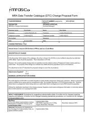
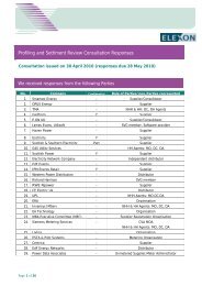
<strong>Code</strong> <strong>of</strong> <strong>Practice</strong> One<strong>Issue</strong> 2 (v<strong>3.0</strong>)_______________________________________________________________________________________APPENDIX BLABELLING OF METERS FOR IMPORT ANDEXPORTA standard method <strong>of</strong> labelling Meters, test blocks, etc is necessary and based on thedefinitions for Import and Export the required labelling shall be as follows.1 ACTIVE ENERGYMeters or Meter Registers shall be labelled “Import” or “Export” according to thediagram “Figure 1”.2 REACTIVE ENERGYWithin the context <strong>of</strong> this code the relationship between Active Energy and Reactive Energycan best be established by means <strong>of</strong> the power factor. The following table gives therelationship:-Flow <strong>of</strong> Active Energy Power Factor Flow <strong>of</strong> Reactive EnergyImportImportImportExportExportExportLaggingLeadingUnityLaggingLeadingUnityImportExportZeroExportImportMeters or Meter Registers for registering Import Reactive Energy should be labelled“Import” and those for registering Export Reactive Energy should be labelled “Export”.Zero<strong>Superseded</strong>______________________________________________________________________________________________________________Balancing and Settlement <strong>Code</strong> Page 31 <strong>of</strong> 36
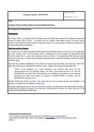
<strong>Code</strong> <strong>of</strong> <strong>Practice</strong> One<strong>Issue</strong> 2 (v<strong>3.0</strong>)_______________________________________________________________________________________APPENDIX B continuedFIGURE 1IMPORT AND EXPORT ACTIVE ENERGY FLOWS CONVENTIONTSBPCVACustomerKeyTSBPGeneratingPlant(CVA)GSPPublicDistributionSystemBP BP BPTransmission SystemDSCPDSCPBPThird PartyGeneratingPlant(SVA)OtherDistributionSystemSVA CustomerPublicDistributionSystemExternalSystem (Dist.or Trans.)BoundaryPoint Import ExportSystemConnectionImport / Export Point Energy Flow Convention for the labelling <strong>of</strong> MetersImport metering measures energy flows away from the Transmission System.Export metering measures energy flows towards the Transmission System.Energy flows between Distribution Systems is by bilateral agreement.GSPBP<strong>Superseded</strong>BPGSPDIBPIBP______________________________________________________________________________________________________________Balancing and Settlement <strong>Code</strong> Page 32 <strong>of</strong> 36
<strong>Code</strong> <strong>of</strong> <strong>Practice</strong> One<strong>Issue</strong> 2 (v<strong>3.0</strong>)_______________________________________________________________________________________Key to abbreviations used in Import / Export DiagramBPDIBPDSCPGSPIBPSCPTSBPMetering PointBoundary PointDistribution Interconnector Boundary PointDistribution System Connection PointGrid Supply PointInterconnector Boundary PointSystem Connection PointTransmission System Boundary Point<strong>Superseded</strong>______________________________________________________________________________________________________________Balancing and Settlement <strong>Code</strong> Page 33 <strong>of</strong> 36
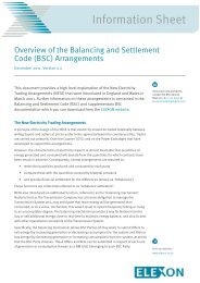
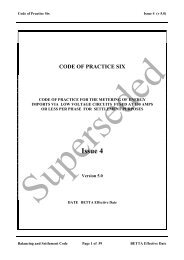
<strong>Code</strong> <strong>of</strong> <strong>Practice</strong> One<strong>Issue</strong> 2 (v<strong>3.0</strong>)_______________________________________________________________________________________APPENDIX CFUSINGThe following diagram shows a typical arrangement for the fusing requirements <strong>of</strong> this <strong>Code</strong><strong>of</strong> <strong>Practice</strong>. The diagram is non-exhaustive and is provided for reference only.Figure 1: Fusing arrangements 7 8 .Note:SupplySecondary VTPrimary VTSource FusesTest Facility and local Means<strong>of</strong> IsolationMainMeterCheckMeterOtherBurden<strong>Superseded</strong>The boundary between Meter Operator Equipment and the Transmission/Distribution SystemOperator is between the local means <strong>of</strong> isolation and the testing facilities.7 Check Meters and other burden may be supplied via an additional secondary winding <strong>of</strong> the primary VT.8 Isolation may be provided by the use <strong>of</strong> solid links or fuses and may be located either side <strong>of</strong> the test terminal block. Wherefuses are to be used, the additional burden shall be accounted for.______________________________________________________________________________________________________________Balancing and Settlement <strong>Code</strong> Page 34 <strong>of</strong> 36
<strong>Code</strong> <strong>of</strong> <strong>Practice</strong> One<strong>Issue</strong> 2 (v<strong>3.0</strong>)_______________________________________________________________________________________APPENDIX DPASSWORDSThe Passwords specified in clause 5.6 shall be subject to the following additionalrequirements:i. The communications protocol employed shall ensure that thePassword <strong>of</strong>fered determines the level <strong>of</strong> access to the data within theMetering Equipment.ii. A counter to log the number <strong>of</strong> illegal attempts (i.e. Passwordcomparison failures) to access Metering Equipment via the local andremote ports shall be incorporated into the log-on process. Thiscounter shall reset to zero at every hour change (i.e. 0100, 0200 etc).iii. If the counter reaches 7, then access is prohibited at all levels until thecounter resets at the next hour change.<strong>Superseded</strong>______________________________________________________________________________________________________________Balancing and Settlement <strong>Code</strong> Page 35 <strong>of</strong> 36
<strong>Code</strong> <strong>of</strong> <strong>Practice</strong> One<strong>Issue</strong> 2 (v<strong>3.0</strong>)_______________________________________________________________________________________APPENDIX EGUIDANCE FOR THE USE OF MULTI COREMETERING CABLESMulti core cables are predominantly used to provide CT and VT signals to the Meter.However, such arrangements may cause additional errors that are not readily apparent to theMetering System designer. This guidance provides information that should be consideredwhen using multi core cables for metering, particularly if used over long cable runs.Consideration shall be given to the cross sectional area <strong>of</strong> the conductors <strong>of</strong> multi core cables:i. In CT circuits the cabling resistance is likely to represent anappreciable component <strong>of</strong> the CT burden and care should be taken toensure that the CT overall burden is not exceeded;ii. For the VT circuits, cabling and fuses introduce high volt drop errors.Fuses with a low current rating tend to have a relatively highresistance value and are variable from fuse to fuse. Careful selection<strong>of</strong> fuses, fuse holders and the doubling <strong>of</strong> cores can be used tomitigate these effects.The proximity <strong>of</strong> CT and VT signals in multi core cables can cause errors due to capacitivecoupling from the voltage to the current curcuits. The effect <strong>of</strong> this coupling is moreprevalent at low loads with long cable runs, in particular with 1 amp rated CTs. One possiblesymptom <strong>of</strong> this condition is that the Meters may advance under no load conditions (circuitenergised but with no load current). This coupling effect may be eliminated by carefulallocation <strong>of</strong> cable core to function, or by running CT and VT signals in separate cables.<strong>Superseded</strong>______________________________________________________________________________________________________________Balancing and Settlement <strong>Code</strong> Page 36 <strong>of</strong> 36