Land Transportation T - Pneumatic Tools Online
Land Transportation T - Pneumatic Tools Online
Land Transportation T - Pneumatic Tools Online

Create successful ePaper yourself
Turn your PDF publications into a flip-book with our unique Google optimized e-Paper software.
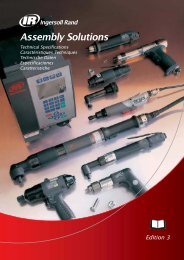
<strong>Land</strong><strong>Transportation</strong><strong>Tools</strong>The Ultimate Power <strong>Tools</strong>
The UltimatePower <strong>Tools</strong>www.cp.com
Table of ContentsCP INTRODUCTIONYour Global Supplier, Your Local Support.................................................................................................................2-3ASSEMBLY TOOLSAssembly <strong>Tools</strong> Selection Guide...............................................................................................................................4-5BATTERY TOOLSSSB Battery Screwdriver ..........................................................................................................................................6-7PLUG & TIGHTENCVIP - Plug & Tighten...............................................................................................................................................8-9Data Transfer Unit ......................................................................................................................................................10CVIP - Angle Head & In-line <strong>Tools</strong> .............................................................................................................................11Accessories ................................................................................................................................................................11CURRENT CONTROL PRODUCTSCVIC Range - Mastering Assembly ......................................................................................................................12-13Torque Range - CVIC <strong>Tools</strong> .......................................................................................................................................14CVIC <strong>Tools</strong>.......................................................................................................................................................... 15-21CVIC Accessories ......................................................................................................................................................22CVIP/C2000 Software ................................................................................................................................................23Technical Features - CVIC Range .............................................................................................................................24Controllers - CVIC Range ..........................................................................................................................................25CS TRANSDUCER CONTROL PRODUCTSCS Range / Electric Transducerized <strong>Tools</strong> ...................................................................................................................26-27SD25 Electric Screwdrivers and CS2700 Controllers ...................................................................................................28-33Torque Range - SD25 Screwdrivers ..........................................................................................................................29SD 25 Electric Screwdrivers - CS ..............................................................................................................................29SD25 Accessories - CS .......................................................................................................................................29-30Visual Supervisor Software - for all CS Products ......................................................................................................31Technical Features - CS2700 Range - CS.................................................................................................................32CS2700 Controllers and Cables ................................................................................................................................3346/66 Series Electric Nutunners and CS4746/4700 Controllers ...................................................................................34-46Torque Range - 46/66 Series Nutrunners ..................................................................................................................3446/66 Series Nutrunners .......................................................................................................................................35-3946/66 Series Accessories......................................................................................................................................40-43Technical Features - CS4746/CS4700 Range - CS...................................................................................................44CS4746 and CS4700 Controllers - CS ......................................................................................................................45CS4746 and CS4700 Controllers - Power Cords and Cables...................................................................................46177/277 Series Electric Nutrunners and CS7000 Controllers.......................................................................................47-49Torque Range - 177/277 Series Nutrunners ..............................................................................................................47177/277 Series Electric Nutrunners - CS ..................................................................................................................47Technical Features - CS7000 Range .........................................................................................................................48CS7000 Controllers ..................................................................................................................................................49CS Networks .........................................................................................................................................................50-51CVI TRANSDUCER CONTROL PRODUCTSCVI II Range/Electric Transducerized <strong>Tools</strong>..................................................................................................................52-53Torque Range - ER and EM <strong>Tools</strong> - CVI II.................................................................................................................54Electric Nutrunners - CVI II Range .......................................................................................................................55-63CVI II Accessories.................................................................................................................................................64-65CVI PC2000 Software ................................................................................................................................................66CVI-net Software........................................................................................................................................................67Technical Features - CVI II Range.............................................................................................................................68Controllers - CVI II ....................................................................................................................................................69CVI II Networks .....................................................................................................................................................70-71TORQUE MEASUREMENT SYSTEMSQuality Assurance .....................................................................................................................................................72Torque and Angle Measuring Units.......................................................................................................................73-75Rotary Transducers - 2500 Series .............................................................................................................................76Digital Rotary Transducers - DRT Series...................................................................................................................77Electronic Hand Torque Wrenches - 1500 Series......................................................................................................78Stationary Transducers - ST4000 Series ...................................................................................................................79Measurement Accessories and Cables......................................................................................................................79CUSTOMIZED SOLUTIONSCustomized Solutions and Services .....................................................................................................................80-81Tubenut and Crowfoot <strong>Tools</strong> ......................................................................................................................................82Other Special <strong>Tools</strong> ....................................................................................................................................................83Bench Stands and Articulated Arms .....................................................................................................................84-85TIGHTENING SERVICESComplete Assembly Solutions ..............................................................................................................................86-87Exceptional Service....................................................................................................................................................88PAGE1
Your global supplier,your local supportAMERICASARGENTINABRAZILCANADACOLOMBIAECUADORMEXICOURUGUAYUSAVENEZUELACP Owned Sales CompaniesDistributorsProduction SitesHemel Hempstead UKNantes FRANCENovi, MI USARock Hill, SC USAQianshao, CHINAMORE than 1000 employees2
ASIA, PACIFICAUSTRALIACHINAHONG KONGINDIAINDONESIAJAPANKOREAMALAYSIANEW ZEALANDPAKISTANPHILIPPINESSINGAPOREEUROPE, MIDDLE EAST, AFRICA, RUSSIAAUSTRIA GERMANY NORWAY TURKEYBAHRAIN GREECE OMAN UKBENELUX IBERIA QATAR UNITED ARAB EMIRATESCYPRUS ICELAND ROMANIADENMARK IRAN RUSSIAE,EUROPE ISRAEL SAUDI ARABIAEGYPT ITALY SOUTH AFRICAEIRE JORDAN SWEDENFINLAND KUWAIT SWITZERLANDFRANCE MALTA SYRIA3
Assembly <strong>Tools</strong> Selection GuideController (if used)CVIP - Plug &TightenSSB Series EAP/EDPCompatible <strong>Tools</strong> Battery SeriesScrewdrivers NutrunnersTorque RangeCVIC SeriesEC/MC Series CurrentControl <strong>Tools</strong>CS2700 SeriesSD25 Series ElectricScrewdrivers1.5 - 12 Nm 3 - 65 Nm 0.2 - 1,350 Nm 1.1 - 5.6 Nm1.1 - 8.8 ft-lb 2.2 - 47.9 ft-lb 0.1 - 995 ft-lb 0.8 - 4.1 ft-lbPages 6-7 8-11 12-25 28-33Product AttributesNo controller required ✔ ✔In-line push to start tools ✔ ✔In-line lever start tools ✔ ✔ ✔Pistol grip (no cable)✔Pistol grip (top cable)✔Pistol grip (standard cable) ✔ ✔Angle wrench ✔ ✔ ✔Fixtured spindles ✔ ✔90 degree Fixtured spindles ✔Standard Crowfoot rangeStandard tubenut rangeStandard offset outputHall Effect <strong>Tools</strong>Resolver tools ✔ ✔✔Mechanical clutch control✔Current control✔Transducer control ✔ ✔CVIP PocketPC SoftwareVisual Supervisor SoftwareCVIPC 2000 SoftwareCVI-NET✔✔✔✔Fieldbus options ✔ ✔Ethernet options ✔ ✔ ✔Multi-channel options ✔ ✔4
CS4746 Series CS4700 Series CS7000 Series CVI II Series46 Series Electric 66 Series Electric 177 &277 SeriesNutrunners Nutrunners Electric NutrunnersER Series NutrunnersEM Series Spindles2 - 18 Nm 20 - 220 Nm 150 - 3,000 Nm 0.35 - 480 Nm 0.5 - 1900 Nm1.4 - 13.2 ft-lb 14.7 - 162 ft-lb 110 - 2,213 ft-lb 0.26 - 354 ft-lb 0.37 - 1400 ft-lb26-27, 31, 34-46, 50-51 26-27, 31, 34-46, 50-51 47-49 52-60, 64, 66-71 52-53, 61-63, 65-71✔ ✔ ✔✔✔ ✔ ✔✔ ✔ ✔✔ ✔ ✔ ✔✔ ✔ ✔ ✔✔✔✔✔✔ ✔ ✔✔✔✔ ✔ ✔✔ ✔ ✔ ✔ ✔✔ ✔ ✔✔✔✔✔✔ ✔ ✔ ✔ ✔✔ ✔ ✔ ✔ ✔✔ ✔ ✔ ✔ ✔5
SSB Battery Screwdriver1.5 to 12 Nm (1.1 to 8.8 ft. lb) - 360 and 750 rpmThe SSB range has been developed to meet the needs for a high quality cordless screwdriverspecifically for the industrial user.High rundown speeds: >700rpm = reduced process timeExcellent torque accuracy assures joint integrity and qualityExtreme durability of components: >200,000 tightening operationsmeans high duty cycles and productivity as well as lower operating costs2.6Ah / 12volt NiMh battery packs can give up to 800 assemblyoperations per chargeT handle shape with 2 position battery clipErgonomic design features for improved operator comfort and outputOptical and audible OK torque indicators and low voltage warning lightSound level
CVIP - Plug & TightenThe Assembly Revolution - Ultimate Precision,Control and ErgonomicsUnbeatable AssemblyQuality• Integrated digital transducer givesaccurate fastening (up to 3% at 6 Sigma)• Tested to ISO 5393• Easy to read LED displayTorque or Torque & Angleassembly strategy3at 6Simple Operation - Plug in anduse in seconds• Plugs into standard 230V/110V• Auto program with self-learning mode• Tamper proof torque programming, eitherdirectly on tool or from pocket PCAUTO setupin secondsShock resistant,composite handleOptional 2 hand start for tubenutapplications, or lower lever positionfor in-line toolsCrowfoot or Tubenut optionsImproveddurabilityof angle headGear boxPatenteddigital torquetransducerBrushlessmotorResolver motorangle controlAdvanced Communicationand Control• Interface via bluetooth pocket PC (Windows Mobile2003)• Program, view results, calibrateAdvanced control & integrationFlexible Assembly - Adapt to allapplications• Modular, changeable outputs• Torque capacity up to 50 ft lbs (65Nm)• 2nd lever start optional for tubenut applicationsA solution for all applications8
Change Your Expectation of Assembly <strong>Tools</strong>• Faster assembly cycle• Significantly longer tool life• Maintenance free brushless motor• Gearbox durability tested to well over 2 million cycles• Energy consumption is significantly less than traditional toolswww.plugandtighten.comwww.plugandtighten.comGround FaultCircuit Interrupter(GFCI)Tool has lowest life cycle cost availableDisplay andkeypadSoft grip handle12 LEDs andbuzzer indicateOK/NOKHighly durable, safetytestedcable and connectorBuilt-in servo driveErgonomic• Low weight, low noise, low torque reaction• Excellent weight distribution, easy to read display• Safety compliant under INTERNATIONAL STANDARD IEC 60745Proven comfort designed with operator input9
Data Transfer UnitThe DTU is a reporting box and tool power supply.There are 2 models of the DTU:• DTU Basic with I/O only• DTU Advanced with I/O and communication to PC or PLC. 10,000 result memory.Connections: I/ORS232EthernetFieldbus (option)MODEL PART DIMENSIONSNUMBER WIDTH HEIGHT DEPTHmm in. mm in. mm in.DTU Basic 615 936 045 0 90 3.5 250 9.8 190 7.5DTU Advanced 615 936 046 0 90 3.5 250 9.8 190 7.5Power supply cableincluding: Power cable + plugPLUG DESCRIPTION PART NO.A European 8.2ft (2.5m) 615 917 201 0B UK 8.2ft (2.5m) 615 917 202 0C US 8.2ft (2.5m) 615 917 203 0A B CACCESSORIESPART NO.• Probibus kit 615 929 021 0• Devicenet kit 615 929 022 0• Modbus+ kit 615 929 023 0• Tool cable 110V 16.4ft (5m) 615 917 485 0• Tool cable 110V 32.8ft (10m) 615 917 486 0• Tool cable 110V 49.2ft (15m) 615 917 487 0• Tool cable 230V 16.4ft (5m) 615 917 480 0• Tool cable 230V 32.8ft (10m) 615 917 481 0• Tool cable 230V 49.2ft (15m) 615 917 482 0• Extension tool cable 32.8ft (10m) 615 917 483 0• Extension tool cable 65.6ft (20m) 615 917 484 010
CVIP - Angle Head & In-line <strong>Tools</strong>2.2 to 47.9 ft.lb. (3 to 65 Nm)MODEL PART MODEL PART OUTPUT TORQUE ROTATIONAL LENGTH WEIGHTNUMBER NUMBER DRIVE RANGE SPEED Lin. type Nm ft.lb. mm in. kg lb230V ModelsTorque Torque + Angle rpm 230VRight angle toolsEAP1.5-15-T-2 615 165 312 0 EAP1.5-15-TA-2 615 165 323 0 3/8 square drive 3-15 2.2-11.0 1020 534.5 21.0 1.85 4.1EAP1.5-20-T-2 615 165 313 0 EAP1.5-20-TA-2 615 165 324 0 3/8 square drive 5-20 3.7-14.7 800 534.5 21.0 1.85 4.1EAP1.5-26-T-2 615 165 314 0 EAP1.5-26-TA-2 615 165 325 0 3/8 square drive 7-26 5.2-19.2 510 534.5 21.0 1.85 4.1EAP2-20-T-2 615 165 315 0 EAP2-20-TA-2 615 165 326 0 3/8 square drive 5-20 3.7-14.7 1320 559.5 22.0 2.0 4.4EAP2-30-T-2 615 165 316 0 EAP2-30-TA-2 615 165 327 0 3/8 square drive 7-30 5.2-22.1 1020 559.5 22.0 2.0 4.4EAP2-40-T-2 615 165 317 0 EAP2-40-TA-2 615 165 328 0 3/8 square drive 10-40 7.4-29.5 800 570.0 22.4 2.1 4.6EAP2-65-T-2 615 165 318 0 EAP2-65-TA-2 615 165 329 0 3/8 square drive 15-65 11-47.9 510 581.5 22.9 2.2 4.8In-line toolsEDP1.5-15-T-2 615 165 319 0 EDP1.5-15-TA-2 615 165 330 0 1/4 hex F 3-15 2.2-11.0 1010 491.5 19.3 1.7 3.7EDP2-24-T-2 615 165 320 0 EDP2-24-TA-2 615 165 331 0 1/4 hex F 5-24 3.7-17.7 1390 516.5 20.3 1.8 3.9EDP2-33-T-2 615 165 321 0 EDP2-33-TA-2 615 165 332 0 3/8 square drive 7-33 5.2-24.3 1010 508.5 20.0 1.85 4.1EDP2-43-T-2 615 165 322 0 EDP2-43-TA-2 615 165 333 0 3/8 square drive 8-43 5.9-31.7 780 508.5 20.0 1.85 4.1110V ModelsTorque Torque + Angle rpm 110VMODEL ØA ØB Hmm in. mm in. mm in.EAP1.5-15-. 28 1.10 27 1.06 45.5 1.79EAP1.5-20-. 28 1.10 27 1.06 45.5 1.79EAP1.5-26-. 28 1.10 27 1.06 45.5 1.79EAP2-20-. 28 1.10 27 1.06 45.5 1.79EAP2-30-. 28 1.10 27 1.06 45.5 1.79EAP2-40-. 35 1.38 27 1.06 51.5 2.03EAP2-65-. 40 1.57 30.5 1.20 57.5 2.26Right angle toolsEAP1.5-15-T-1 615 165 334 0 EAP1.5-15-TA-1 615 165 345 0 3/8 square drive 3-15 2.2-11.0 690 534.5 21.0 1.85 4.1EAP1.5-20-T-1 615 165 335 0 EAP1.5-20-TA-1 615 165 346 0 3/8 square drive 5-20 3.7-14.7 540 534.5 21.0 1.85 4.1EAP1.5-26-T-1 615 165 336 0 EAP1.5-26-TA-1 615 165 347 0 3/8 square drive 7-26 5.2-19.2 340 534.5 21.0 1.85 4.1EAP2-20-T-1 615 165 337 0 EAP2-20-TA-1 615 165 348 0 3/8 square drive 5-20 3.7-14.7 890 559.5 22.0 2.0 4.4EAP2-30-T-1 615 165 338 0 EAP2-30-TA-1 615 165 349 0 3/8 square drive 7-30 5.2-22.1 690 559.5 22.0 2.0 4.4EAP2-40-T-1 615 165 339 0 EAP2-40-TA-1 615 165 350 0 3/8 square drive 10-40 7.4-29.5 540 570.0 22.4 2.1 4.6EAP2-65-T-1 615 165 340 0 EAP2-65-TA-1 615 165 351 0 3/8 square drive 15-65 11-47.9 340 581.5 22.9 2.2 4.8In-line toolsEDP1.5-15-T-1 615 165 341 0 EDP1.5-15-TA-1 615 165 352 0 1/4 hex F 3-15 2.2-11.0 680 491.5 19.3 1.7 3.7EDP2-24-T-1 615 165 342 0 EDP2-24-TA-1 615 165 353 0 1/4 hex F 5-24 3.7-17.7 940 516.5 20.3 1.8 3.9EDP2-33-T-1 615 165 343 0 EDP2-33-TA-1 615 165 354 0 3/8 square drive 7-33 5.2-24.3 680 508.5 20.0 1.85 4.1EDP2-43-T-1 615 165 344 0 EDP2-43-TA-1 615 165 355 0 3/8 square drive 8-43 5.9-31.7 525 508.5 20.0 1.85 4.11246357ACCESSORIESITEMPART NO.1 Mounting plate with telescopic spindle 615 396 547 02 2nd lever start option 615 396 553 03 Reaction handle 615 396 554 04 Horizontal Bail, included with the tools 615 396 562 05 Horizontal Bail, swivel 615 396 529 06 Vertical Bail 4670037 Reaction bar ring, included with the EDP tools 615 396 551 5• Plastic protective cover EAP. -15 to 30 615 573 064 0• Plastic protective cover EAP.-40 615 573 065 0• Plastic protective cover EAP.-65 615 573 066 0• Power cable EU 230V 5m (16.4ft.) 615 917 470 0• Power cable EU 230V 5m (16.4ft.) with GFI 615 917 476 0• Power cable UK 230V 5m (16.4ft.) 615 917 472 0• Power cable UK 230V 5m (16.4ft.) with GFI 615 917 478 0• Power cable US 230V 5m (16.4ft.) with GFI 615 917 477 0• Power cable US 110V 5m (16.4ft.) with GFI 615 917 479 0• CVIPocket software (Windows mobile 2003) 615 927 558 011
CVIC RangeThe CVIC system offersimproved control, joint integrityand many more advantages overconventional tools.EasySetupThe EB (Electric Brushless) tools are accuratelycontrolled to rundown and error proof bymonitoring the power consumption andangle rotation.The CVIC range can be setup fast - allparameters are auto-programmed as soon asthe controller is switched on (all tool have a built in ID).3 Programming options:• Quick Pprogramming: enter only the target torque and max angle. TheCVIC will optimize all other parameters to tighten to torque and monitorangle.• Learning: simply enter the target torque, make between 3 and 5tightenings and the CVIC will “learn” the joint rate and setup all parameters togive optimum performance.• Standard Programming: Each parameter can be modified as the applicationrequires.2 Software versions are available in the CVIC range:Version L: allows you to tighten at a programmed torque after self-learning ofthe joint and allows you to detect incorrect tightenings.Version H: all the functions of the L plus on-controller memory with 7 cycles,each with up to 20 different phases.Search sequence - Rundown - Final tighten - Action on Not OK - last 100results stored.Reliability &Quality of tighteningReduce Costof maintenanceThe quality of each tightening is checked with an OK or Not OK reportshown by LEDs on the tool, on the CVIC display and with an output onthe I/O connector.The control of the assembly station by the CVIC eliminates the riskof delivering non conforming parts, (missed screws, re-tightening,etc.).To ensure traceability of the fastening process results caneither be reviewed on the controller - H version stores last100 results - or sent to a database for storage.The CVIC systems have been extensively fordurability and exceeded all standards. TheEB (brushless) motor is maintenancefree.Reading of the tool featuresTool rotating testReading of input/output12
Mastering AssemblyMULTICVIC - Flexible multi-spindle systemControl system 1 to 32 channels- The MODCVIC is the rack version of the CVIC. It has noscreen or keyboard. It is programmed by the CVIS/CVIPC2000 software.2 software versions L and H are available, with all the functionsof the CVIC controller. The H version can be connected to a PCnetwork to make programming easier.- The MULTICVIC consists of MODCVIC modules and aCPUCVI which is the interface between a PLC and themodules. The CPUCVI centralises the control functions andthe results while monitoring the MODCVIC.- The flexibility of the MULTICVIC can be further increased byoperating the available 26 input and 32 output connections ofthe CPUCVI module through an ISaGRAF process controlapplication integrated in this module.ISaGRAFI/OCPUCVICVIPC2000 softwareThis common software of all CP EB controllers can program and collect results of CVICrange. It is possible to connect up to 32 controllers through a PC network (H version).Socket trayThe socket tray allows you to automatically select a tightening cycle by picking theappropriate socket.Bar code reader- it selects a tightening cycle- the bar code number is saved with the tightening results.Connectionof peripheralIntegral tool memory, which contains the torque tuning and tighteningparameters, makes this a ready-to-use ‘plug and play’ tool.Long lifetime gearboxAdapter forgeared offsethead (crowfoot)Tool connection offers high resistance to torsion and reaction.OperatorComfortOptimised anglehead for extremelylong life because ofspecial treatmentof angle pinions.Designed with Ergosense in mind:- Very low sound level, less than 70 dBA.- Ergo stop function and comfort grip maximizesoperator comfort.13
Torque RangePerformances of Portable electric nutrunners - series ECL, ECP, ECA and ECDIn-line & Angle headROTATIONALSPEED rpmECL1 2000ECL3 2000ECL5 2000ECL8 2000ECL11 1500ECLA11 1500Torque Nm 0 0.5 1 1.5 2 5 10 20 30Pistol gripROTATIONALSPEED rpmECP3L 2000ECP5L 2000ECP10L 1540ECP20L 790ECP20S 1540ECP30S 1070ECP40S 680ECP3LT 2000ECP5LT 2000ECP10LT 1540ECP20LT 790Torque Nm 0 0.5 1 1.5 2 5 10 20 30 40Angle headROTATIONALSPEED rpmECA15 1140ECA20 1480ECA30 1140ECA40 900ECA60 570ECA70 690ECA90 550ECA115 380ECA125 360ECA150 300ECA200 220Torque Nm 0 5 10 15 20 30 50 100 150 200In-lineROTATIONALSPEED rpmECD5 2065ECD20 1560ECD30 1100ECD50 1030ECD70 650ECD120 400Torque Nm 0 5 10 15 20 30 50 100 150 200Performances of Fixtured electric spindles - series MC and MCLIn-lineROTATIONALSPEED rpmMC35-10 2067MC35-20 2067MC38-10 1287MC38-20 1092MC51-10 650MC51-20 403MC60-10 923MC60-20 507MC60-30 299MC80-10 286MC80-20 195MC80-30 130MC80-40 91MC106-10 52MC106-20 39Torque Nm 0 10 20 50 100 150 200 300 400 600 800 1000 1200 1400AngleROTATIONALSPEED rpmMCL38-20 1092MCL51-20 403MCL60-20 481MCL60-30 312MCL80-40 91Torque Nm 0 10 20 50 100 150 200 300 400 60014
Electric Nutrunners - CVIC RangeTorque range from 0.2 to 11 Nm (ECL..)(0.15 to 8.1 ft.lb) in 3 modelsAdjustableLeverNo maintenance Brushless electric motorProgrammable speed from 30 to 2000 rpmSmooth start accelerationErgostop function to reduce torque reactionLow shock loading into componentLow noise level
Pistol Grip Electric Nutrunners - CVICECP3L - ECP5L - ECP10L - ECP20L - ECP20S - ECP30S - ECP40S1 to 40 Nm (0.7 to 29.5 ft.lb) - 680 to 2000 rpmECP30SECP3L - ECP5L ECP10L - ECP20LECP20SECP40SAccessories: see page 22MODEL PART OUTPUT TORQUE ROTATIONAL LENGTH WEIGHTNUMBER DRIVE RANGE SPEED AT Lin. Nm ft.lb rpm/230 V rpm/110 V mm in. kg lb.ECP3L 615 165 199 0 1/4-in hex F 1.0-3 0.7-2.2 2000 2000 196 7.7 1.0 2.2ECP5L 615 165 200 0 1/4-in hex F 1.7-5 1.3-3.7 2000 1515 196 7.7 1.0 2.2ECP10L 615 165 201 0 1/4-in hex F 3.0-10 2.2-7.4 1540 1000 196 7.7 1.1 2.4ECP20L 615 165 202 0 1/4-in hex F 7.0-20 4.9-14.8 790 515 196 7.7 1.1 2.4ECP20S 615 165 203 0 1/4-in hex F 7.0-20 4.9-14.8 1540 1000 221 8.7 1.2 2.6ECP30S 615 165 204 0 3/8-in square 10.0-30 7.4-22.1 1070 700 217 8.5 1.2 2.6ECP40S 615 165 262 0 3/8-in square 10.0-40 7.4-29.5 680 442 274 10.7 1.7 3.7Pistol Grip Electric Nutrunners - CVICECP3LT - ECP5LT - ECP10LT - ECP20LT1 to 20 Nm (0.7 to 14.8 ft.lb) - 790 to 2000 rpmAccessories: see page 22MODEL PART OUTPUT TORQUE ROTATIONAL LENGTH WEIGHTNUMBER DRIVE RANGE SPEED AT Lin. Nm ft.lb rpm/230 V rpm/110 V mm in. kg lb.ECP3LT 615 165 231 0 1/4-in hex F 1.0-3 0.7-2.2 2000 2000 196 7.7 1.0 2.2ECP5LT 615 165 232 0 1/4-in hex F 1.7-5 1.3-3.7 2000 1960 196 7.7 1.0 2.2ECP10LT 615 165 233 0 1/4-in hex F 3.0-10 2.2-7.4 1540 1000 196 7.7 1.1 2.4ECP20LT 615 165 234 0 1/4-in hex F 7.0-20 5.2-14.8 790 510 196 7.7 1.1 2.416
Angle Head Electric Nutrunners - CVICECA15 - ECA20 - ECA30 - ECA40 - ECA605 to 60 Nm (3.7 to 44.2 ft.lb) - 570 to 1480 rpmMODEL H Ø1 Ø2mm in. mm in. mm in.ECA15 45.5 1.8 28 1.1 27.0 1.06ECA20 - ECA30 45.5 1.8 28 1.1 27.0 1.06ECA40 51.5 2.0 35 1.4 27.0 1.06ECA60 57.5 2.3 40 1.6 30.5 1.20ECA15Quick change chuckP.N 615 396 262 0Accessories: see page 22MODEL PART SQUARE TORQUE ROTATIONAL LENGTH WEIGHTNUMBER DRIVE RANGE SPEED AT Lin. Nm ft.lb rpm/230 V rpm/110 V mm in. kg lb.ECA15 615 165 192 0 3/8-in 5-15 3.7-11.0 1140 855 406 16.0 1.3 2.9ECA20 615 165 100 0 3/8-in 7-20 5.2-14.7 1480 1110 431 16.9 1.7 3.7ECA30 615 165 101 0 3/8-in 10-30 7.4-22.1 1140 855 431 16.9 1.7 3.7ECA40 615 165 102 0 3/8-in 13-40 9.6-29.5 900 675 441 17.4 1.8 4.0ECA60 615 165 103 0 3/8-in 20-60 14.7-44.2 570 427 453 17.8 1.9 4.2Angle Head Electric Nutrunners - CVICECA70 - ECA90 - ECA115 - ECA125 - ECA150 - ECA20023 to 200 Nm (16.9 to 147.5 ft.lb) - 220 to 690 rpmECA70 - ECA90 - ECA115 - ECA125 - ECA150ECA200MODEL H Ø1mm in. mm in.ECA70- ECA90 - ECA115 66 2.6 45 1.77ECA125 - ECA150 69 2.7 50 1.97Accessories: see page 22MODEL PART SQUARE TORQUE ROTATIONAL LENGTH WEIGHTNUMBER DRIVE RANGE SPEED AT Lin. Nm ft.lb rpm/230 V rpm/110 V mm in. kg lb.ECA70 615 165 104 0 1/2-in 23-70 16.9-51.6 690 517 538 21.2 3.3 7.3ECA90 615 165 105 0 1/2-in 30-90 22.1-66.4 550 412 538 21.2 3.3 7.3ECA115 615 165 106 0 1/2-in 39-115 28.7-84.8 380 285 538 21.2 3.3 7.3ECA125 615 165 188 0 1/2-in 40-125 29.5-92.2 360 270 541 21.3 3.6 7.9ECA150 615 165 189 0 1/2-in 50-150 36.8-110.6 300 225 541 21.3 3.6 7.9ECA200 615 165 190 0 3/4-in 70-200 51.6-147.5 220 165 591 23.3 3.8 8.417
In-line Electric Nutrunners - CVICECD5 - ECD20 - ECD302 to 30 Nm (1.3 to 22 ft.lb) - 1100 to 2065 rpmECD30ECD5ECD20MODEL PART OUTPUT TORQUE ROTATIONAL LENGTH WEIGHTNUMBER DRIVE RANGE SPEED AT Lin. Nm ft.lb rpm/230 V rpm/110 V mm in. kg lb.ECD5 615 165 068 0 1/4-in hex F 2-6 1.5-4.4 2065 1548 346 13.6 1.0 2.4ECD20 615 165 093 0 1/4-in hex F 7-20 5.2-14.7 1560 1170 388 15.3 1.5 3.3ECD30 615 165 094 0 3/8-in square 10-30 7.4-22 1100 825 380 15.0 1.5 3.3In-line Electric Nutrunners - CVICECD50 - ECD70 - ECD12016 to 120 Nm (11.8 to 88.5 ft.lb) - 400 to 1030 rpmAccessories: see page 22MODELDmm in.ECD50 12.0 0.47ECD70- ECD120 16.5 0.65Accessories: see page 22MODEL PART SQUARE TORQUE ROTATIONAL LENGTH WEIGHTNUMBER DRIVE RANGE SPEED AT Lin. Nm ft.lb rpm/230 V rpm/110 V mm in. kg lb.ECD50 615 165 095 0 3/8-in square 16-50 11.8-36.8 1030 772 456 17.9 2.6 5.7ECD70 615 165 096 0 1/2-in square 23-70 16.9-51.6 650 487 461 18.1 2.6 5.7ECD120 615 165 097 0 1/2-in square 40-120 29.5-88.5 400 300 488 19.2 3.1 6.818
Fixtured Electric Spindles - CVICMC35-10 - MC35-20 - MC38-10 -MC38-202.5 to 45 Nm (1.8 to 33.2 ft.lb) - 1092 to 2067 rpmMODELØ1mmin.MC35-10 35 1.38MC35-20 35 1.38MC38-10 - MC38-20 38 1.50Accessories: see page 22MODEL PART SQUARE TORQUE ROTATIONAL TELESCOPIC MIN. CENTRE LENGTH WEIGHTNUMBER DRIVE RANGE SPEED AT DISTANCE Lin. Nm ft.lb rpm/230 V rpm/110 V mm in. mm in. mm in. kg lb.MC35-10 615 165 107 0 3/8-in 2.5-8 1.8-5.9 2067 1344 50 1.97 43.2 1.7 276 10.9 1.7 3.7MC35-20 615 165 108 0 3/8-in 5.0-15 3.7-11 2067 1344 50 1.97 43.2 1.7 301 11.8 2.0 4.4MC38-10 615 165 109 0 3/8-in 10.0-30 7.4-22.1 1287 837 50 1.97 43.2 1.7 347 13.7 2.0 4.4MC38-20 615 165 110 0 3/8-in 15.0-45 11.0-33.2 1092 710 50 1.97 43.2 1.7 347 13.7 2.0 4.4Fixtured Electric Spindles - CVICMC51-10 - MC51-20 - MC60-10 - MC60-20 - MC60-3025 to 190 Nm (18.4 to 140 ft.lb) - 299 to 923 rpmMODEL Ø1 Ø2 Dmm in. mm in. mm in.MC51-10 - MC51-20 51 2.01 43 1.70 113.0 4.45MC60-10 60 2.36 60 2.36 113.0 4.45MC60-20 - MC60-30 60 2.36 60 2.36 121.5 4.78Accessories: see page 22MODEL PART SQUARE TORQUE ROTATIONAL TELESCOPIC MIN. CENTRE LENGTH WEIGHTNUMBER DRIVE RANGE SPEED AT DISTANCE Lin. Nm ft.lb rpm/230 V rpm/110 V mm in. mm in. mm in. kg lb.MC51-10 615 165 111 0 1/2-in 25-70 18.4-51.6 650 423 50 1.97 51.2 2.0 366 14.4 2.9 6.4MC51-20 615 165 112 0 1/2-in 45-135 33.2-99.5 403 262 50 1.97 51.2 2.0 393 15.4 3.5 7.7MC60-10 615 165 113 0 1/2-in 30-60 22.1-44.2 923 600 50 1.97 60.2 2.4 417 16.4 4.8 10.6MC60-20 615 165 114 0 3/4-in 60-110 44.2-81.1 507 330 50 1.97 60.2 2.4 417 16.4 4.8 10.6MC60-30 615 165 115 0 3/4-in 80-190 59.0-140 299 195 50 1.97 60.2 2.4 453 17.8 5.2 11.519
Fixtured Electric Spindles - CVICMC80-10 - MC80-20 - MC80-30 - MC80-40 - MC106-10 - MC106-20100 to 1350 Nm (73.7 to 995 ft.lb) - 39 to 286 rpmMODEL Ø1 Dmm in. mm in.MC80-10 - MC80-20 80 3.15 140 5.51MC80-30 - MC80-40 80 3.15 148 5.82MC106-10 - MC106-20 106 4.17 148 5.82Accessories: see page 22MODEL PART SQUARE TORQUE ROTATIONAL TELESCOPIC MIN. CENTRE LENGTH WEIGHTNUMBER DRIVE RANGE SPEED AT DISTANCE Lin. Nm ft.lb rpm/230 V rpm/110 V mm in. mm in. mm in. kg lb.MC80-10 615 165 116 0 3/4-in 100-195 73.7-144 286 186 60 2.36 80.2 3.2 480 18.9 9.8 21.6MC80-20 615 165 117 0 3/4-in 150-300 110.5-221 195 127 60 2.36 80.2 3.2 480 18.9 9.8 21.6MC80-30 615 165 118 0 1-in 220-420 162.1-309 130 85 60 2.36 80.2 3.2 480 18.9 9.8 21.6MC80-40 615 165 119 0 1-in 270-600 199.0-442 91 59 60 2.36 80.2 3.2 480 18.9 9.8 21.6MC106-10 615 165 120 0 1-in 500-1100 368.5-811 52 34 60 2.36 106.2 4.2 556 21.9 15.0 33.1MC106-20 615 165 121 0 1-in 600-1350 442.2-995 39 25 60 2.36 106.2 4.2 556 21.9 15.0 33.1Fixtured Electric Spindles - CVICMCL38-2015 - 45 Nm (11 - 33.2 ft.lb) - 1092 rpmR9Accessories: see page 22MODEL PART SQUARE TORQUE ROTATIONAL TELESCOPIC MIN. CENTRE LENGTH WEIGHTNUMBER DRIVE RANGE SPEED AT DISTANCE Lin. Nm ft.lb rpm/230 V rpm/110 V mm in. mm in. mm in. kg lb.MCL38-20 615 165 124 0 3/8-in 15-45 11-33.2 1092 710 50 1.97 43.2 1.7 140.5 5.53 3.0 6.620
Fixtured Electric Spindles - CVICMCL51-20 - MCL60-20 - MCL60-3045 to 190 Nm (33.2 to 140 ft.lb) - 312 to 481 rpmMODEL Ø1 Ø2 D Emm in. mm in. mm in. mm in.MCL51-20 51 2.01 43 1.69 113 4.45 412.5 16.2MCL60-20 60 2.36 60 2.36 121 4.76 448.5 17.7MCL60-30 60 2.36 60 2.36 121 4.76 448.5 17.7Accessories: see page 22MODEL PART SQUARE TORQUE ROTATIONAL TELESCOPIC MIN. CENTRE LENGTH WEIGHTNUMBER DRIVE RANGE SPEED AT DISTANCE Lin. Nm ft.lb rpm/230 V rpm/110 V mm in. mm in. mm in. kg lb.MCL51-20 615 165 125 0 1/2-in 45-135 33.2-99.5 403 262 50 1.97 51.2 2.0 166 6.5 4 8.8MCL60-20 615 165 126 0 3/4-in 60-110 44.2-81.1 481 313 50 1.97 60.2 2.4 178 7.0 6 13.2MCL60-30 615 165 127 0 3/4-in 80-190 58.9-140 312 203 50 1.97 60.2 2.4 178 7.0 6 13.2Fixtured Electric Spindles - CVICMCL80-40270 - 600 Nm (199 - 442 ft.lb) - 91 rpmAccessories: see page 22MODEL PART SQUARE TORQUE ROTATIONAL TELESCOPIC MIN. CENTRE LENGTH WEIGHTNUMBER DRIVE RANGE SPEED AT DISTANCE Lin. Nm ft.lb rpm/230 V rpm/110 V mm in. mm in. mm in. kg lb.MCL80-40 615 165 128 0 1-in 270-600 199-442 91 59 60 2.4 80.2 3.2 241 9.49 11 24.221
Accessories1234567ECL / ECP / ECA / ECDACCESSORIES INCLUDEDITEMPART NO.• Side handle for ECP / ECL8 467033• Fixed suspension bail for ECP.LT 467003• Stationary suspension bail for ECA15/20/30/40/60 / ECD 615 571 056 0• Stationary suspension bail for ECA90/115/125/150/200 615 571 050 0• Square drive ball 3 /8" for ECA15/20/30/40/60 615 770 028 0• Reaction bar for ECD20/30 615 396 191 0• Reaction bar for ECD50/70/120 615 595 259 0• Long trigger lever for ECD5 615 396 192 0OPTIONAL ACCESSORIESITEMMC / MCLPART NO.• Rotary right angle tool connector for ECP 615 396 300 0• Suspension bail for ECP.L 615 396 121 0• Suspension bail on a swivel for ECA20/30/40/60 / ECD5/20/30 615 396 228 0• Suspension bail on a swivel for ECA70/90/115/125/150/200 / ECD50/70/120 615 396 229 0• Top cable length 4m for ECP.LT 615 917 420 0• Reaction bar ring for ECA60 615 396 226 0• Reaction bar ring for ECA70/90/115/125/150 615 396 227 0• Reaction bar ring for ECA200 615 396 230 0• Long trigger lever for ECA / ECD 615 396 192 0• Ball for ECA15/20/30/40 615 770 028 0Spring Loaded Shafts and Bearings Support for ECL1 Bit Adaptor 1037822 Spring Loaded Shaft 25mm (1") stroke, 3 /8" Sq Drive 1083423 Shaft Support and Nose Mount 108412Nose Mounts for ECL4 Nose Mount 108392Offset Head and Spring Loaded Shaft for ECL5 Offset Head, Offset 30mm (1.18") 3849936 Spring Loaded Shaft 25mm (1") stroke, 3 /8" Sq Drive 108352Screwdriver Bit Adaptor for ECL7 3 /8" Square to 1 /4" Hex Power Adaptor 108322Cable for ECP / ECA / ECDCable length: 3m 5m 10m 15m 20m 25m 30m• Nutrunnerscable 615 917 461 0 615 917 462 0 615 917 464 0 615 917 465 0• Extension cable 615 917 222 0 615 917 224 0 615 917 225 0 615 917 226 0 615 917 227 0 615 917 228 0Socket Tray• Socket tray (sockets not supplied) 615 936 005 0Cable length: 1m 5m 10m 15m• Cable for socket tray 615 917 241 0 615 917 242 0 615 917 244 0 615 917 245 0Reporting Box• Reporting Box 615 936 001 0OPTIONAL ACCESSORIESPART NO.• Motor/In-line connector assembly kit for MC35-10 to MC51-20 / MCL38-20/MCL51-20 615 396 198 0• Motor/In-line connector assembly kit for MC60-10 to MC106-20 / MCL60-20/30/MCL80-40 615 396 199 0Transducer-holder from MC tool• 3/8-in square drive MC35/MC38 615 396 426 0• 1/2-in square drive MC51/MC60.10 615 396 427 0• 3/4-in square drive MC60.20/MC60.30 615 396 428 0• 3/4-in square drive MC80.10/MC80.20 615 396 429 0• 1-in square drive MC80.30/40/MC106 615 396 430 0Cable for MC & MCL toolsMODCVICCable length: 5m 10m 15m 20m 25m 30m• Motor cable 615 917 232 0 615 917 234 0 615 917 235 0 615 917 236 0 615 917 237 0 615 917 238 0• Motor extension cable 615 917 222 0 615 917 224 0 615 917 225 0 615 917 226 0 615 917 227 0 615 917 228 022
CVIP2000 SoftwareProgram Parameters and Monitor DataCVI PC2000 software (Windows compatible) is auser friendly tool able to program tightening cycles,collect and display results and curves from alltightening controllers in real time.The Advanced network version allows the connection of up to 32controllers in RS422 mode and many more through an Ethernet link.Real time control mode• Display all stations connected• Display and save results• Display tightening reports• Print results after each tightening or from date to dateProgramming mode• General parameters of controllers: peripherals, fieldbuses, Ethernet,• Tightening cycles, up to 250• Electric brushless tool features• Downloading of all parameters to stationsDisplaying of all stations programmedAccess to main functions with soft keyFriendly InterfaceStatistical analysis mode• Standards: ISO, CNOMO, NF• Display and print:HistogramsSPCControl charts, mean, range, standard deviationMaintenance mode• Access to tool counters, partial number of cycles and total numberof cycles performed by the tool• Test mode to check torque transducer, angle encoder, brushless motor, etc…• Complete backup/restore of StationsCycles and phases programming modeEasy ControlComplete Statistical PackageFrom torque control up to yield point strategyMODELPARTNUMBERCVIS/CVIC PC2000 1 install 615 927 521 0CVIS/CVIC PC2000 5 install 615 927 534 0CVIS/CVIC PC2000 25 install 615 927 536 0MODELPARTNUMBERCVI PC2000 standard 1 install 615 927 522 0CVI PC2000 standard 5 install 615 927 526 0CVI PC2000 standard 25 install 615 927 537 0MODELPARTNUMBERCVI PC2000 advance 1 install 615 927 523 0CVI PC2000 advance 5 install 615 927 535 0CVI PC2000 advance 25 install 615 927 538 023
Technical FeaturesCVIC RangeMAIN FUNCTIONSVERSIONSLHSTANDARD ADVANCEDQuick cycle with self-learning of the joint ✔ ✔Number of cycles in the controller 0 15Number of cycle in the tool 1 1Number of phases 3 20Batch count (99 OK reports) ✔ ✔TIGHTENING RESULTSTorque + Angle + Date + Time + Report 100TYPES OF PHASES IN A CYCLESearch Sequence✔Run Down ✔ ✔Torque controlled final speed phase ✔ ✔Angle-controlled final speed phase✔Angle-controlled run reverse✔Restart cycle in case of defect✔Prevailing torque monitoring✔STRATEGIESTorque control and angle monitoring ✔ ✔Angle control and torque monitoring✔DISPLAY AND PROGRAMMINGDisplayLCD display ✔ ✔Keyboard8 buttons keyboard ✔ ✔ReportsLEDs 6 6PC Software WindowsCVIPC2000 *: program cycles, collect, display and save results, run statistics ✔ ✔Connection ‘point to point’Connection through a network (32 controllers)✔*All CVIPC2000 versions are compatible with CVICsMAINTENANCEAccess to all tool parameters (tool memory) ✔ ✔Autotest of the complete system ✔ ✔Spindle rotation test ✔ ✔Input/Output selection ✔ ✔Date of the last maintenance operation ✔ ✔Total and partial cycle counters ✔ ✔PERIPHERALSInput/Output 2/4 8/8PC point-to-point connection (RS232) ✔ ✔PC network connection (RS422)✔Bar code reader connection to select a cycle number (RS232)✔MODELCONTROLLER for low torque tools CVIC L-2 CVIC H-2MODULE for low torque tools MODCVIC L-2 MODCVIC H-2CONTROLLER for the other tools CVIC L-4 CVIC H-4MODULE for the other tools MODCVIC L-4 MODCVIC H-4MAINS SUPPLYSingle -phase 110/230 Volts ✔ ✔24
ControllersCVIC - MODCVICABPIC MODEL PART TOOLS CONSUMPTION MAINS DIMENSIONS WEIGHTREF NUMBER (current) SUPPLY WIDTH HEIGHT115V 230V 50/60 hertz mm in. mm in. mm in. kg lb.CVIC CONTROLLERA CVIC L-2 615 932 608 0 ECD5/ECL-ECPL/MC35.10/ECA15 4A 2A Single-phase 260 10.2 270 10.6 170 6.7 5 11.0A CVIC H-2 615 932 610 0 ECD5/ECL-ECPL/MC35.10/ECA15 4A 2A 100 to 250 V 260 10.2 270 10.6 170 6.7 5 11.0A CVIC L-4 615 932 609 0 Other tools 8A 4A Single-phase 260 10.2 270 10.6 170 6.7 5 11.0A CVIC H-4 615 932 611 0 Other tools 8A 4A 100 to 250 V 260 10.2 270 10.6 170 6.7 5 11.0MODCVIC MODULEB MODCVIC L-2 615 932 612 0 ECD5/ECP3 to 20L/ECL/MC35-10 4A 2A Single-phase 100 3.94 320 12.6 270 10.6 4 8.8B MODCVIC H-2 615 932 602 0 ECD5/ECP3 to 20L/ECL/MC35-10 4A 2A or 100 3.94 320 12.6 270 10.6 4 8.8B MODCVIC L-4 615 932 613 0 Other tools 8A 4A three-phase 100 3.94 320 12.6 270 10.6 4 8.8B MODCVIC H-4 615 932 604 0 Other tools 8A 4A 100 to 250 V 100 3.94 320 12.6 270 10.6 4 8.8START-UP KIT to be ordered with the controllerIncluding: Plug + Literature + ConnectorPLUG LITERATURE PART NO.A French 615 928 040 0C English 615 928 041 0A English 615 928 046 0B English 615 928 049 0A German 615 928 042 0A Spanish 615 928 043 0D Italian 615 928 044 0A Dutch 615 928 048 0A Swedish 615 928 045 0OPTIONAL ACCESSORIESPART NO.• CVICPC NETWORK 2000 software 615 927 523 0• PC cable Length 2m (78.7") 615 917 047 0• Printer cable Length 2m (78.7") 615 917 011 0• CVIS/CVICPC2000 1 Installation 615 927 521 0• CVIS/CVICPC2000 5 Installations 615 927 534 0• CVIS/CVICPC2000 25 Installations 615 927 536 0A B C D25
CS RangeControllersFlexibilityBasic andAdvanced Models• Basic models have small scrollingdisplays.• Advanced models give full information and have largebright screen designed to reduces eye strain.FlexibleUp to 32 parameter sets, 16 sequences per channel. Easy setupof all applications, from simple rundowns to complex sequences.InstantCommunicationProcessManagementStructured Logical ProgrammingApplications can be programmed from the controller keypad, using theVisual Supervisor (VS) program, or via a PLC.VS Software• VS is detachable when a laptop PC loaded with the VS program is connected toa CS controller. VS on a laptop PC is portable so it can be used to program manyCS controllers.• VS can also be embedded (permanently installed) in the built-in computers of large,multi-spindle CS controllers.• Setup is automatic. User simply enters the IP address into the controller and VS.Communication begins as soon as the tool is attached and the system is powered on.• “Drag and drop” makes programming of parameter sets and sequences easy. VSdisplays fastening rundown results, graphs, statistics, an event log, and diagnosticsinformation for communications, tool and I/O.Process ManagementMulti-spindle CS controllers can be designed for as many as 32 spindles in an RS-485network, and for as many as 99 spindles using Ethernet connections.CS controller network options: Ethernet, DeviceNet, Modbus TCP/Ethernet IP,Profibus DPV1, PFCS/Terminal Server, etc.TraceabilityGraphsQuality AssuranceController memory ensures traceability via recall of tightening results: final torque,final angle, torque rate, date, time, bar code, tightening curves and more.Up to 2,000 readings (torque, angle, date, time, report).Curves: 1 OK curve and 1 not OK curve per channel per rundown.StatisticsVS automatically calculates statistics for torque, angle, or torque and angleresults.• Results are displayed on CS controllers with keypad/display, or onthe laptop screen when VS is attached to the basic CS controller• Statistic include StDev, Cpk, CR, 6 Sigma, Mean, Low,High, Range• Printing of full statistics reportModularityFrom the simplest to themost advanced applications26
Acceptable/Unacceptable (OK/NOK) SignalsThe quality of each tightening is displayed on all tools:Green (OK) and Red (Not OK) for the SD25 Screwdrivers.Green (OK) and user programmable red and yellow lights, factory set for torqueand angle rejects• All tools have a built-in torque transducer with leading edge strain gauge technology• Angle monitoring, digital communication between tool/controller ensure joint qualityElectric Transducerized <strong>Tools</strong>Tightening QualityTightening Strategies to Meet the Joint SpecificationAll CS controllers perform continuous process monitoring. Tthe following control andmonitoring strategies are available:ControlMonitoring• Torque only• Torque and angle• Yield• Torque only• Torque and angle• Yield• Prevailing torque• Self-tap• Re-hitErgonomic, User-Friendly• SD25 Screwdrivers weigh just 1 lb. (0.4 kg).• Nutrunners have programmable green, yellow and red LEDs with a handle displaythat shows tightening result and programable scrolling message.• 46 and 66 Series tools are high speed to minimizeoperator reaction.No Need to Re-Calibrate ControllersCS controllers automatically recognize the intelligent tool that’s attached.Controllers need NO calibrationMaintenanceGear greasing is the only maintenance required. Digital display in the tool handleshows when maintenance is needed.IntelligenceIntelligence is built into every tool providing:• Model number• Display• Build date• Auxiliary pushbutton• Serial number• Cycle count• Torque parameters • Locked rotor count• Speed parameters • Overtemperature count• Calibration data• Preventive maintenance counter• Angle count/revolution• Last calibration• Last repairErgonomicsOperator comfortProductivityProcess<strong>Tools</strong>Large range of tools(1-3,000 Nm)Low maintenanceCost SavingsAutomatic self diagnosiswith user-friendly messagesReduction of assemblyinspection proceduresChoose This For This Torque Tool DesignController Tool RangeCS2700 SD25 Series 1 - 5.6 Nm • IntelligentScrewdrivers• Hall effect sensor (when speed andCS4746 46 Series 5 - 15 Nm operator comfort matter)Nutrunners • VS Software compatibleCS4700 66 Series 2 - 226 NmNutrunnersWorkstation or Multi SD25, 1 - 226 NmMulti CS5000 Multi 46/66 SeriesspindlesCS7000 177 /277 Series 150 - • IntelligentMulti CS7000 Nutrunners 3,000 Nm • Resolver (when precision matters)• VS Software compatible27
Torque RangePerformances of electric screwdrivers - series SD25Electric Screwdrivers - CSSD25 ScrewdriverROTATIONALSPEED rpmSD25I010 1700SD25I020 1100SD25I035 800SD25I050 500Torque Nm 0 0.5 1.0 1.5 2 5 10 20 30LMODEL PART OUTPUT TORQUE ROTATIONAL LENGTH WEIGHTNUMBER DRIVE RANGE SPEED Lin. type in.lb in.oz kgf.cm Nm rpm mm in. kg lb.SD25I010LAQ2 615 004 098 2 1/4 quick release chuck 10 160 11.5 1.1 1700 238.7 9.4 .41 .9SD25I020LAQ2 615 004 098 3 1/4 quick release chuck 20 320 23.0 2.3 1100 238.7 9.4 .41 .9SD25I035LAQ2 615 004 098 4 1/4 quick release chuck 35 560 40.3 3.9 800 238.7 9.4 .41 .9SD25I050LAQ2 615 004 098 5 1/4 quick release chuck 50 800 57.6 5.6 500 238.7 9.4 .41 .9SD25I010BAQ2 615 004 012 1 1/4 quick release chuck 10 160 11.5 1.1 1700 238.7 9.4 .41 .9SD25I020BAQ2 615 004 012 4 1/4 quick release chuck 20 320 23.0 2.3 1100 238.7 9.4 .41 .9SD25I035BAQ2 615 004 012 7 1/4 quick release chuck 35 560 40.3 3.9 800 238.7 9.4 .41 .9SD25I050BAQ2 615 004 012 9 1/4 quick release chuck 50 800 57.6 5.6 500 238.7 9.4 .41 .9SD25I010MAQ2 615 004 012 2 1/4 quick release chuck 10 160 11.5 1.1 1700 238.7 9.4 .41 .9SD25I020MAQ2 615 004 012 5 1/4 quick release chuck 20 320 23.0 2.3 1100 238.7 9.4 .41 .9SD25I035MAQ2 615 004 012 8 1/4 quick release chuck 35 560 40.3 3.9 800 238.7 9.4 .41 .9SD25I050MAQ2 615 004 013 0 1/4 quick release chuck 50 800 57.6 5.6 500 238.7 9.4 .41 .9KEY TO THE SD25 SCREWDRIVER 8-DIGIT PREFIXExample: SD25I010SD 25 I 010Screwdriver Series Type: In-line Capacity: in.lbAND THE SUFFIX:SUFFIX: L, B, or M A Q2Applications• White goods/appliances• Electronics• Automotive dashboards, electronics,headlights, headliners• Light assembly where error-proofing is essentialTRIGGER LEVERBOTH TRIGGER AND PUSH-TO-STARTMOUNTEDALUMINUM HEAD1/4-IN QUICK RELEASE CHUCKAccessories: see page 30SD25OPTIONAL ACCESSORIESITEM MODEL NUMBER PART NO.Foam grip for In-line SD25 Screwdriver 31-80-39445 615 005 147 2Foam grip for In-line SD25 Screwdriver, no cutout 31-80-39445P 615 005 147 3Pistol grip attachment for In-line SD25 Screwdriver 49-SD-10111 615 004 090 7Suspension bail (all SD25 Screwdrivers) 49-SD-10112 615 004 090 8Mounting plate, double flange (for fixtured mounting) 49-SD-10121 615 005 309 5Mounting plate, single flange (for close fixtured mounting) 49-SD-10125 615 005 309 629
AccessoriesSD25 Tool-to-Controller Cables, CEREQUIRED ACCESSORIES to be ordered with controllerLENGTHWEIGHTWITH STRAIGHT CONNECTORS m ft. kg lb. MODEL NUMBER PART NUMBERScrewdriver to Controller Cable 1.5 5 .23 .5 299230-81050C 615 004 110 2Screwdriver to Controller Cable 3.0 10 .45 1.0 299230-81100C 615 004 070 6Screwdriver to Controller Cable 4.6 15 .68 1.5 299230-81150C 615 004 070 9Screwdriver to Controller Cable 6.1 20 .90 2.0 299230-81200C 615 004 071 2Screwdriver to Controller Cable 7.6 25 1.13 2.5 299230-81250C 615 004 0714Screwdriver to Controller Cable 9.1 30 1.36 3.0 299230-81300C 615 004 110 3Screwdriver to Controller Cable 10.7 35 1.58 3.5 299230-81350C 615 004 098 6Screwdriver to Controller Cable 12.2 40 1.81 4.0 299230-81400C 615 004 098 7Screwdriver to Controller Cable 13.7 45 2.04 4.5 299230-81450C 615 004 098 8Screwdriver to Controller Cable 15.2 50 2.26 5.0 299230-81500C 615 004 098 9SD25 Tool-to-Controller Cables, CEOPTIONAL ACCESSORIESLENGTHWEIGHTWITH HEAVY DUTY CONNECTORS m ft. kg lb. MODEL NUMBER PART NUMBERScrewdriver to Controller Cable 1.5 5 .23 .5 299230-81050CH 615 004 110 4Screwdriver to Controller Cable 3.0 10 .45 1.0 299230-81100CH 615 004 110 5Screwdriver to Controller Cable 4.6 15 .68 1.5 299230-81150CH 615 004 110 6Screwdriver to Controller Cable 6.1 20 .90 2.0 299230-81200CH 615 004 110 7Screwdriver to Controller Cable 7.6 25 1.13 2.5 299230-81250CH 615 004 110 8Screwdriver to Controller Cable 9.1 30 1.36 3.0 299230-81300CH 615 004 110 9Screwdriver to Controller Cable 10.7 35 1.58 3.5 299230-81350CH 615 004 111 0Screwdriver to Controller Cable 12.2 40 1.81 4.0 299230-81400CH 615 004 111 1Screwdriver to Controller Cable 13.7 45 2.04 4.5 299230-81450CH 615 004 111 2Screwdriver to Controller Cable 15.2 50 2.26 5.0 299230-81500CH 615 004 111 3LENGTHWEIGHTWITH RIGHT ANGLE CONNECTORS m ft. kg lb. MODEL NUMBER PART NUMBERScrewdriver to Controller Cable 1.5 5 .23 .5 299230-81050CR 615 004 092 2Screwdriver to Controller Cable 3.0 10 .45 1.0 299230-81100CR 615 004 070 7Screwdriver to Controller Cable 4.6 15 .68 1.5 299230-81150CR 615 004 071 0Screwdriver to Controller Cable 6.1 20 .90 2.0 299230-81200CR 615 004 099 3Screwdriver to Controller Cable 7.6 25 1.13 2.5 299230-81250CR 615 004 099 4Screwdriver to Controller Cable 9.1 30 1.36 3.0 299230-81300CR 615 004 071 7Screwdriver to Controller Cable 10.7 35 1.58 3.5 299230-81350CR 615 004 099 5Screwdriver to Controller Cable 12.2 40 1.81 4.0 299230-81400CR 615 004 099 6Screwdriver to Controller Cable 13.7 45 2.04 4.5 299230-81450CR 615 004 099 7Screwdriver to Controller Cable 15.2 50 2.26 5.0 299230-81500CR 615 004 099 8LENGTHWEIGHTEXTENSION CABLES m ft. kg lb. MODEL NUMBER PART NUMBERScrewdriver to Controller Cable 6.1 20 .90 2.0 299230-81200CE 615 004 111 4Screwdriver to Controller Cable 9.1 30 1.36 3.0 299230-81300CE 615 004 111 5Screwdriver to Controller Cable 15.2 50 2.26 5.0 299230-81500CE 615 004 111 6Screwdriver to Controller Cable 23.1 70 3.17 7.0 299230-81700CE 615 004 111 730
Visual SupervisorOne program for all CS controllers and intelligent tighteningVisual Supervisor (VS) is the user-friendly Windows ® -based software program that simplifies setup andtroubleshooting of these intelligent tightening system controllers:• CS2700• CS4700• CS4746• CS5000• Workstation• CS7000Such systems can have:• One intelligent electric brushless tightening tool and a single-channel controller• Assorted intelligent electric nutrunners operated by one or more single or multi-channel controllers in anetwork (with as many as 32 spindles total, 99 with Ethernet).VS can exchange tightening rundown results and real time fastening cycle status with industry buses such as:• DeviceNet• Modbus TCP/Ethernet IP• Profibus DPV1VS makes it easy to set up, collect and manage your tightening torque strategy.• Enter parameter values• Assign soft I/O using the drag and drop method• Create sequences and steps• Read bar codes off parts• View, collect, graph, print and store fastening rundown data on a hard drive or network database• Troubleshoot errors quickly• Adapt to wireless communicationVS lets you choose the torque strategy that is right for your application, whether it calls for hand-held tools orfixtured spindles.VS automatically collects data for local drive storage. Data can be saved to any third-party database programfor network storage, retrieval and sharing.VS Program user interface screens include:• Readings – For a single tool the VS readings screen displays a large box showing the torque, angle (indegrees) and the parameter set of the last cycle. The box is green when the fastening is accepted, or redwhen rejected. If multiple tools are monitored, VS displays a status line for each.• Setup – utilizes Windows ® tabs and drag and drop features for easy setup of tightening system inputs,outputs, and parameter sets for each tool that is attached.• Diagnostics – provides I/O, transducer and communications information for troubleshooting.• Graphs – automatically saves accepted and rejected fastening cycle waveforms as graphs, updatesgraphs between cycles, and displays/prints multiple graphs.• Event Log – provides a running list of the date, time, spindle name, address and description, user andstation of all tightening performed.Detachable and Embedded Versions of VS• VS loaded on a laptop PC running WindowsXP ® or 2000 is connected via RS-232 port to asingle-channel CS controller. The portable VSprogram may be taken from one CS controller toanother, therefore it is detachable.• VS is permanently installed (embedded) on thebuilt-in industrial computer of multi-spindle CScontrollers (for up to 32 channels) operating onWindows NT ® . VS is also embedded on theCS5000 Workstation which controls multi-spindle46/66 Series nutrunner systems.MODEL PART DESCRIPTIONNUMBER464000SVSSFTWR* 615 004 139 9 Visual Supervisor (VS) Program, Version X.XX, CDR* X’s indicate version. Number changes for each release31
Technical FeaturesCS2700 RangeMAIN FUNCTIONSCS2700VERSIONSControl Strategies (Use any of these with any/all of the Monitoring Strategies)Torque only ✔ ✔Torque and angle ✔ ✔Yield ✔ ✔Monitoring StrategiesTorque only ✔ ✔Torque and angle ✔ ✔Yield ✔ ✔Prevailing torque ✔ ✔Self-tap ✔ ✔Re-hit ✔ ✔CS5000Number of channels 1 2–32Number of parameter sets 1–32 1–32Number of sequences (phases) 16 total 16Number of steps (cycles) 32/sequence 32/sequenceBatch count 99 99Real time statistics – 6 Sigma, CR, Cpk, St Dev, Pop, Mean, Low, High, Range ✔ ✔Bar code reading ✔ ✔Synchronization of spindles ✔ ✔TIGHTENING RESULTSTorque + Angle + Date + Time + Report Up to 2,000/controller Up to 2,000/controllerNumber of curves 1 accept, 1 reject 1 accept, 1 reject/spindleTIGHTENING STRATEGIESEXTERNAL CONNECTIVITYInput 8 8Output 8 8RS232 programming port✔Serial printer/barcode scanner port (dual function) ✔ ✔High speed RS485 port (SDLC) ✔ ✔ADVANCED OPTIONSEthernet or SDLC or RF ✔ ✔Fieldbus: DeviceNet, Modbus TCP/Ethernet IP, Profibus DPV1 ✔ ✔Plant Floor Communication System (PFCS) ✔ ✔MAINTENANCEAccess to all tools parameters for setup ✔ ✔Access to all I/O for troubleshooting ✔ ✔Serial/Diagnostics port✔PROGRAMMINGFull keypad + large LCD screen + function keys✔Laptop PC laded with VS software ✔ ✔Keyboard or touch screen monitor✔Visual Supervisor (VS) software ✔ ✔Supply Voltage 120V✔Supply Voltage 230V ✔ ✔Supply Voltage 480V with step down transformer✔CS5000 ControllersModel Part Number Description Dimensions (W x H x D) Weight485000-36269 615 004 070 3 CS5000 Workstation, Industrial PC with built-in monitor, 52.1 x 54.6* x 41.9** cm 35.22 kgkeypad/mouse, SDLC 20.5 x 21.5* x 16.5** in 77.66 lb*Height includes mounting flanges**Depth includes handlesMulti-spindle CS5000 Controllers can be customized for your particular application.32
CS2700 ControllersTotal tightening functionality is packaged in a space-saving enclosure.Slim new CS2700 Controllers are designed for use with the SD25 Series transducerizedelectric screwdrivers (1 to 50 in.-lb).Controller configurations include:1 Basic + with parameter set selection dial; no keypad, small scrolling display2 Advanced with keypad/display user interface, EthernetEach model comes with RS-485 connection for daisy-chaining to other controllers.Limited programming can be performed via the keypad/display on the Advanced model.Both models may be programmed using the Visual Supervisor (VS) program. VS is loadedonto a laptop PC that connects to the controller via RS-232 port.Data that the controller collects about the selected fastening strategy and results can bestored to internal memory, off-line, a network database, or communicated viaprogrammable logic controller (PLC) for sharing with in-plant workstations.Field bus option kits for all models are available.Each configuration is available in 120V or 230V. Tool control module is 7A. Designed tomeet automotive OEM tightening, size and CE, CSA requirements. Enclosure measures17.4 x 45.9 x 33.3 cm / 6.85 x 18.07 x 13.12 in (width x height x depth). Approximateweight is 13.6 kg / 30 lb.1 2CS2700 CONTROLLERMODEL PART NUMBER PSET KEYPAD USED TCM AMPS, COMM FIELD INPUT CABLE SAFETYDIAL DISPLAY WITH COLOR BUS* VOLTS CONNECTOR STD.C2700AP1V112 615 004 108 2 1 No SD25 7A - White — None 120 Screwdriver CE, CSAC2700A01K112051 615 004 108 5 0 Yes SD25 7A - White Ethernet None 120 Screwdriver CE, CSAC2700AP1V212 615 004 108 3 1 No SD25 7A - Blue — None 230 Screwdriver CE, CSAC2700A01K212051 615 004 090 9 0 Yes SD25 7A - Blue Ethernet None 230 Screwdriver CE, CSA• Additional models are available. Consult your CP sales representative.OPTION KITS MODEL CP PART NUMBERCS2700/4746/4700 Ethernet Option (for Basic+ models only) 1 244700KETHN051 615 004 138 7CS2700/4746/4700 Devicenet Option 2 244700KDNET054 615 004 138 8CS2700/4746/4700 Profibus DPV1 Option 2 244700KPBUS058 615 004 138 9CS2700/4746/4700 Modbus TCP/Ethernet IP Option 2 244700KMTCP05A 615 004 139 0CS2700/4746/4700 PFCS/Terminal Server Option 2 244700KPFCSB51 615 004 139 11Ethernet is already installed on Advanced controllers with keypad/display so this option is not required.2When this option is selected, the Ethernet option 1 must also be ordered.Contact your CP Representative for more information.ABCS2700 Power CableREQUIRED ACCESSORIES to be ordered with controllerLENGTHPLUG DESCRIPTION m ft. MODEL NO. PART NO.A China CS2700/4700/4746 Controller power cord, 230V 2.5 8 244100-42222 615 004 092 3B England CS2700/4700/4746 Controller power cord, 230V 2.5 8 244100-40105 615 004 085 5C Europe CS2700/4700/4746 Controller power cord, 230V 2.5 8 244100-40106 615 004 085 6D USA/North America CS2700/4700/4746 Controller power cord, 230V 2.5 8 244100-40107 615 004 085 7D USA/North America CS2700/4700/4746 Controller power cord, 120V 2.5 8 244100-40526 615 004 092 1CDCS2700 Controller CablesOPTIONAL ACCESSORIESLENGTHWEIGHTITEM m ft. kg lb. MODEL NO. PART NO.Controller to printer/PC programming kit 1.8 6 .23 .5 244000-35087 615 004 092 3Serial cable for data transfer, laptop VS toCS2700 controller 6.1 20 .23 .5 41-41-0109FN 615 005 258 1Controllers for fixtured multiple screwdriver applications may be customized to your requirements. Contact your sales representative.33
Torque RangePerformances of electric nutrunners - series 46 and 66ROTATIONAL46 Series Pistol Grip (Handheld and Fixtured) SPEED rpmT046P005 1630T046P010 1050T046P015 670Torque Nm 0 0.5 1.0 1.5 2 5 10 20 30ROTATIONAL66 Series Pistol Grip (Handheld and Fixtured) SPEED rpmT066P020 2290T066P030 1485T066P035 1177T066P045 937T066P060 630T066P075 424Torque Nm 0 5 10 15 20 50 100 150 200ROTATIONAL46 Series Angle Head (Handheld and Fixtured) SPEED rpmT046A015 680T046A019 540T046A024 430Torque Nm 0 0.5 1.0 1.5 2 5 10 20 30ROTATIONAL66 Series Angle Head (Handheld and Fixtured) SPEED rpmT066A026 1526T066A041 990T066A050 765T066A065 610T066A100 280T066A126 235T066A156 200T066A186 160T066A226 1540Torque Nm 0 5 10 15 20 50 100 150 200ROTATIONAL46 Series In-line (Handheld and Fixtured) SPEED rpmT046I005 1630T046I010 1050T046I015 670Torque Nm 0 0.5 1.0 1.5 2 5 10 20 30ROTATIONAL66 Series In-line (Handheld and Fixtured) SPEED rpmT066I020 2290T066I030 1485T066I035 1177T066I045 937T066I060 630T066I075 424T066I100 345T066I150 208T066I170Torque Nm 0 5 10 15 20 50 100 150 200Torque Information atYour Fingertips!Close up of display and four-way positioningAll CP Techmotive 46 and 66 Series nutrunners contain the following components in thetool handle, providing the operator with information at hand:• Programmable multipurpose pushbutton that can be used for CycleComplete, multiple parameter set selection, data send (transmission), etc.• Forward/reverse button• Green, yellow and red indicator/status lights• 4-place alphanumeric digital display that can be positioned four waysto accommodate vertical and left-hand use of the tool to show• Torque and angle values• OK and other status information• 15-character scrolling messages• Identification of the selected parameter set34
46 Series Pistol Grip Electric Nutrunners - CS5 to 15 Nm (3.7 to 11.1 ft.lb)Used with a CS4746 or CS5000 ControllerA suspension bail (A046BS-P37694/615 004 074 6) and analuminum reaction bar and nut kit (A066SIL2R/615 004 138 5)are included.66 Series Pistol Grip Electric Nutrunners - CS**Change the detent from pin to ball by substituting a B for the P inthe Model No.Accessories: see pages 40–43MODEL PART OUTPUT DETENT TORQUE ROTATIONAL LENGTH WEIGHTNUMBER DRIVE RANGE SPEED ATin. type Nm ft.lb kgfm rpm mm in. kg lb.T046P005SSP2 615 004 022 7 1/4 square drive Pin 5 3.7 0.5 1630 216 8.5 1.6 3.6T046P005SSP3 615 004 022 8 3/8 square drive Pin 5 3.7 0.5 1630 216 8.5 1.6 3.6T046P005SSQ04 615 004 022 9 1/4 hex socket Quick chuck 5 3.7 0.5 1630 216 8.5 1.7 3.8T046P005SSQ07 615 004 096 8 7/16 hex socket Quick chuck 5 3.7 0.5 1630 274 10.8 1.7 3.8T046P010SSP2 615 004 023 0 1/4 square drive Pin 10 7.4 1.0 1050 269 10.6 1.6 3.6T046P010SSP3 615 004 023 1 3/8 square drive Pin 10 7.4 1.0 1050 274 10.8 1.7 3.8T046P010SSQ04 615 004 023 2 1/4 hex socket Quick chuck 10 7.4 1.0 1050 274 10.8 1.7 3.8T046P010SSQ07 615 004 096 9 7/16 hex socket Quick chuck 10 7.4 1.0 1050 269 10.6 1.6 3.6T046P015SSP3 615 004 023 5 3/8 square drive Pin 15 11.1 1.5 670 274 10.8 1.7 3.8T046P015SSQ07 615 004 097 0 7/16 hex socket Quick chuck 15 11.1 1.5 670 274 10.8 1.7 3.820 to 75 Nm (14.7 to 55.3 ft.lb)Used with a CS4700 or CS5000 ControllerA suspension bail (A046BS-P37694/615 004 074 6) isincluded with all models.For 20-45 Nm models, an aluminum reaction bar and nut kit(A066SIL2R/615 004 138 5) is included.For 60-75 Nm models, a long steel reaction bar and nut kit(A066SIL3R/615 004 083 4) is included.Accessories: see pages 40–43MODEL PART OUTPUT DETENT TORQUE ROTATIONAL LENGTH WEIGHTNUMBER DRIVE RANGE SPEED ATin. type Nm ft.lb kgfm rpm mm in. kg lb.T066P020SSP2 615 004 097 1 1/4 square drive Pin 20 14.7 2.0 2290 269 10.6 1.6 3.6T066P020SSP3 615 004 034 1 3/8 square drive Pin 20 14.7 2.0 2290 269 10.6 1.6 3.6T066P020SSQ04 615 004 034 2 1/4 hex socket Quick chuck 20 14.7 2.0 2290 274 10.8 1.7 3.8T066P020SSQ07 615 004 097 2 7/16 hex socket Quick chuck 20 14.7 2.0 2290 274 10.8 1.7 3.8T066P030SSP3 615 004 044 4 3/8 square drive Pin 30 22.1 3.1 1485 269 10.6 1.6 3.6T066P030SSQ04 615 004 097 3 1/4 hex socket Quick chuck 30 22.1 3.1 1485 274 10.8 1.7 3.8T066P030SSQ07 615 004 097 4 7/16 hex socket Quick chuck 30 22.1 3.1 1485 274 10.8 1.7 3.8T066P035SSP3 615 004 034 6 3/8 square drive Pin 35 25.8 3.6 1177 269 10.6 1.6 3.6T066P035SSQ04 615 004 097 5 1/4 hex socket Quick chuck 35 25.8 3.6 1177 274 10.8 1.7 3.8T046P035SSQ07 615 004 097 6 7/16 hex socket Quick chuck 35 25.8 3.6 1177 274 10.8 1.7 3.8T066P045SSP3 615 004 034 8 3/8 square drive Pin 45 33.2 4.6 937 269 10.6 1.6 3.6T066P045SSQ04 615 004 097 7 1/4 hex socket Quick chuck 45 33.2 4.6 937 274 10.8 1.7 3.8T066P045SSQ07 615 004 097 8 7/16 hex socket Quick chuck 45 33.2 4.6 937 274 10.8 1.7 3.8T066P060SSP4 615 004 035 0 1/2 square drive Pin 60 44.3 6.1 630 302 11.9 1.8 3.9T066P075SSP4 615 004 035 1 1/2 square drive Pin 75 55.3 7.6 424 302 11.9 1.8 3.935
46 Series Angle Head Electric Nutrunners - CS15 to 24 Nm (11.1 to 17.7 ft.lb)Used with a CS4746 or CS5000 ControllerA mounting plate kit (A066SRAP/615 004 083 5)is available for all models.No reaction bar is used.Short lever kit (483066-S/615 005 285 0)is standard.Accessories: see pages 40–43MODEL PART OUTPUT DETENT TORQUE ROTATIONAL LENGTH WEIGHTNUMBER DRIVE RANGE SPEED ATin. type Nm ft.lb kgfm rpm mm in. kg lb.T046A015SHP2 615 004 092 7 1/4 square drive Pin 15 11.1 1.5 680 353 13.9 1.5 3.3T046A015SHP3 615 004 022 3 3/8 square drive Pin 15 11.1 1.5 680 353 13.9 1.5 3.3T046A019SHP2 615 004 092 8 1/4 square drive Pin 19 14.0 1.9 540 353 13.9 1.5 3.3T046A019SHP3 615 004 022 5 3/8 square drive Pin 19 14.0 1.9 540 353 13.9 1.5 3.3T046A024SHP2 615 004 092 9 1/4 square drive Pin 24 17.7 2.4 430 353 13.9 1.5 3.3T046A024SHP3 615 004 022 6 3/8 square drive Pin 24 17.7 2.4 430 353 13.9 1.5 3.366 Series Angle Head Electric Nutrunners - CS26 to 226 Nm (19.2 to 166 ft.lb)Used with a CS4700 or CS5000 ControllerA mounting plate kit (A066SRAP/615 004 083 5)is available for all models.No reaction bar is used.Short lever kit (483066-S/615 005 285 0)is standard.Accessories: see pages 40–43MODEL PART OUTPUT DETENT TORQUE ROTATIONAL LENGTH WEIGHTNUMBER DRIVE RANGE SPEED ATin. type Nm ft.lb kgfm rpm mm in. kg lb.T066A026SHP2 615 004 093 0 1/4 square drive Pin 26 19.2 2.7 1526 383 15.1 1.8 4.0T066A026SHP3 615 004 024 6 3/8 square drive Pin 26 19.2 2.7 1526 383 15.1 1.8 4.0T066A041SHP3 615 004 026 7 3/8 square drive Pin 41 30.2 4.2 990 409 16.1 1.9 4.1T066A041SHP4 615 004 093 1 1/2 square drive Pin 41 30.2 4.2 990 409 16.1 1.9 4.1T066A050SHP3 615 004 027 6 3/8 square drive Pin 50 36.9 5.1 765 409 16.1 1.9 4.1T066A050SHP4 615 004 027 7 1/2 square drive Pin 50 36.9 5.1 765 409 16.1 1.9 4.1T066A065SHP3 615 004 028 8 3/8 square drive Pin 65 47.9 6.6 610 427 16.8 2.1 4.6T066A065SHP4 615 004 028 9 1/2 square drive Pin 65 47.9 6.6 610 427 16.8 2.1 4.6T066A100SHP4 615 004 093 2 1/2 square drive Pin 100 73.7 10.2 280 517 20.2 2.2 7.4T066A126SHP4 615 004 031 5 1/2 square drive Pin 126 92.9 12.8 235 543 21.3 4.0 8.9T066A156SHP4 615 004 031 6 1/2 square drive Pin 156 115.1 15.9 200 543 21.3 4.0 8.9T066A156SHP6 615 004 093 3 3/4 square drive Pin 156 115.1 15.9 200 543 21.3 4.0 8.9T066A186SHP6 615 004 093 4 3/4 square drive Pin 186 137.1 18.9 160 543 21.3 4.0 8.9T066A226SHP6 615 004 033 5 3/4 square drive Pin 226 166.6 23.0 154 543 21.3 4.0 8.9**Change the detent from pin to ball by substituting a B for the P in the Model No.36
46 Series In-line Electric Nutrunners - CSUsed with a CS4746 or CS5000 ControllerAn aluminum reaction bar and nut kit (A066SIL2R/615 004 138 5) isincluded.Short lever kit (483066-S/615 005 285 0)is standard.5 to 15 Nm (3.7 to 11.1 ft.lb)Accessories: see pages 40–43MODEL PART OUTPUT DETENT TORQUE ROTATIONAL LENGTH WEIGHTNUMBER DRIVE RANGE SPEED ATin. type Nm ft.lb kgfm rpm mm in. kg lb.T046I005SSP2 615 004 044 8 1/4 square drive Pin 5 3.7 0.5 1630 320 12.6 1.2 2.6T046I005SSP3 615 004 044 9 3/8 square drive Pin 5 3.7 0.5 1630 320 12.6 1.2 2.6T046I005SSQ04 615 004 045 0 1/4 hex socket Quick chuck 5 3.7 0.5 1630 320 12.6 1.2 2.6T046I005SSQ07 615 004 094 6 7/16 hex socket Quick chuck 5 3.7 0.5 1630 320 12.6 1.2 2.6T046I010SSP2 615 004 046 0 1/4 square drive Pin 10 7.4 1.0 1050 320 12.6 1.2 2.6T046I010SSP3 615 004 046 1 3/8 square drive Pin 10 7.4 1.0 1050 320 12.6 1.2 2.6T046I010SSQ04 615 004 046 2 1/4 hex socket Quick chuck 10 7.4 1.0 1050 320 12.6 1.2 2.6T046I010SSQ07 615 004 094 7 7/16 hex socket Quick chuck 10 7.4 1.0 1050 320 12.6 1.2 2.6T046I015SSP2 615 004 047 4 1/4 square drive Pin 15 11.1 1.5 670 320 12.6 1.2 2.6T046I015SSP3 615 004 047 5 3/8 square drive Pin 15 11.1 1.5 670 320 12.6 1.2 2.6T046I015SSQ04 615 004 047 7 1/4 hex socket Quick chuck 15 11.1 1.5 670 320 12.6 1.2 2.6T046I015SSQ07 615 004 094 8 7/16 hex socket Quick chuck 15 11.1 1.5 670 320 12.6 1.2 2.6Used with a CS4700 or CS5000 ControllerFor the 20-45 models, an aluminum reaction bar and nut kit(A066SIL2R/615 004 138 5) is included.For the 60-170 Nm models, a long steel reaction bar and nut kit(A066SIL3R/615 004 083 4) is included.Short lever kit (483066-S/615 005 285 0)is standard.66 Series In-line Electric Nutrunners - CS20 to 170 Nm (14.7 to 125 ft.lb)**Change the detent from pin to ball or thru-hole by substituting a B or a Tfor the P in the Model No.Accessories: see pages 40–43MODEL PART OUTPUT DETENT TORQUE ROTATIONAL LENGTH WEIGHTNUMBER DRIVE RANGE SPEED ATin. type Nm ft.lb kgfm rpm mm in. kg lb.T066I020SSP3 615 004 049 1 3/8 square drive Pin 20 14.7 2.0 2290 376 14.8 1.7 3.7T066I020SSQ04 615 004 094 9 1/4 hex socket Quick chuck 20 14.7 2.0 2290 376 14.8 1.7 3.7T066I020SSQ07 615 004 095 0 7/16 hex socket Quick chuck 20 14.7 2.0 2290 376 14.8 1.7 3.7T066I030SSP3 615 004 050 0 3/8 square drive Pin 30 22.1 3.1 1485 376 14.8 1.7 3.7T066I030SSQ04 615 004 095 1 1/4 hex socket Quick chuck 30 22.1 3.1 1485 376 14.8 1.7 3.7T066I030SSQ07 615 004 095 2 7/16 hex socket Quick chuck 30 22.1 3.1 1485 376 14.8 1.7 3.7T066I035SSP3 615 004 050 4 3/8 square drive Pin 35 25.8 3.6 1177 376 14.8 1.7 3.7T066I035SSQ04 615 004 095 3 1/4 hex socket Quick chuck 35 25.8 3.6 1177 376 14.8 1.7 3.7T066I035SSQ07 615 004 095 4 7/16 hex socket Quick chuck 35 25.8 3.6 1177 376 14.8 1.7 3.7T066I045SSP3 615 004 051 5 3/8 square drive Pin 45 33.2 4.6 937 376 14.8 1.7 3.7T066I045SSQ04 615 004 095 5 1/4 hex socket Quick chuck 45 33.2 4.6 937 376 14.8 1.7 3.7T066I045SSQ07 615 004 051 8 7/16 hex socket Quick chuck 45 33.2 4.6 937 376 14.8 1.7 3.7T066I060SSP4 615 004 052 4 1/2 square drive Pin 60 44.2 6.1 630 403 15.9 2.2 4.9T066I075SSP4 615 004 053 2 1/2 square drive Pin 75 55.3 7.6 424 403 15.9 2.2 4.9T066I100SSP4 615 004 053 9 1/2 square drive Pin 100 73.8 10.2 345 403 15.9 2.2 4.9T066I150SSP4 615 004 054 7 1/2 square drive Pin 150 110.6 15.3 208 403 15.9 2.2 4.9T066I170SSP4 615 004 054 9 1/2 square drive Pin 170 125.3 17.3 208 403 15.9 2.2 4.937
46 Series Fixtured Angle Head Electric Spindles - CS15 to 24 Nm (11.1 to 17.7 ft.lb)Used with a CS4746 or CS5000 ControllerA mounting plate kit (A066SRAP/615 004 083 5) is includedfor all models.No reaction bar is used.Accessories: see pages 40–43MODEL PART OUTPUT DETENT TORQUE ROTATIONAL LENGTH WEIGHTNUMBER DRIVE RANGE SPEED ATin. type Nm ft.lb kgfm rpm mm in. kg lb.T046A015MHP2 615 004 093 5 1/4 square drive Pin 15 11.1 1.5 680 353 13.9 1.4 3.1T046A015MHP3 615 004 022 1 3/8 square drive Pin 15 11.1 1.5 680 353 13.9 1.4 3.1T046A019MHP2 615 004 093 6 1/4 square drive Pin 19 14.0 1.9 540 353 13.9 1.4 3.1T046A019MHP3 615 004 022 4 3/8 square drive Pin 19 14.0 1.9 540 353 13.9 1.4 3.1T046A024MHP2 615 004 093 7 1/4 square drive Pin 24 17.7 2.4 430 353 13.9 1.4 3.1T046A024MHP3 615 004 093 8 3/8 square drive Pin 24 17.7 2.4 430 353 13.9 1.4 3.166 Series Fixtured Angle Head Electric Spindles - CS26 to 65 Nm (19.2 to 166 ft.lb)Used with a CS4700 or CS5000 ControllerFor 26-65 Nm models, a mounting plate kit(A066SRAP/615 004 083 5) is included.For 126-226 Nm models, a hevay duty mounting plate kit(A066SRAPH/615 004 104 2) is included.No reaction bar is used on 66 Series Angle Head nutrunners.Accessories: see pages 40–43MODEL PART OUTPUT DETENT TORQUE ROTATIONAL LENGTH WEIGHTNUMBER DRIVE RANGE SPEED ATin. type Nm ft.lb kgfm rpm mm in. kg lb.T066A026MHP2 615 004 093 9 1/4 square drive Pin 26 19.2 2.7 1526 383 15.1 1.7 3.9T066A026MHP3 615 004 094 0 3/8 square drive Pin 26 19.2 2.7 1526 383 15.1 1.7 3.9T066A041MHP3 615 004 026 4 3/8 square drive Pin 41 30.2 4.2 990 409 16.1 1.8 4.0T066A041MHP4 615 004 094 1 1/2 square drive Pin 41 30.2 4.2 990 409 16.1 1.8 4.0T066A050MHP3 615 004 027 2 3/8 square drive Pin 50 36.9 5.1 765 409 16.1 1.8 4.0T066A050MHP4 615 004 094 2 1/2 square drive Pin 50 36.9 5.1 765 409 16.1 1.8 4.0T066A065MHP3 615 004 028 5 3/8 square drive Pin 65 47.9 6.6 610 427 16.8 2.0 4.5T066A065MHP4 615 004 094 3 1/2 square drive Pin 65 47.9 6.6 610 427 16.8 2.0 4.5T066A100MHP4 615 004 103 6 1/2 square drive Pin 100 73.7 10.2 280 517 20.2 2.2 7.4T066A126MHP4 615 004 031 4 1/2 square drive Pin 126 92.9 12.8 235 543 21.3 4.0 8.9T066A156MHP4 615 004 094 4 1/2 square drive Pin 156 115.1 15.9 200 543 21.3 4.0 8.9T066A156MHP6 615 004 094 5 3/4 square drive Pin 156 115.1 15.9 200 543 21.3 4.0 8.9T066A186MHP6 615 004 032 6 3/4 square drive Pin 186 137.1 18.9 160 543 21.3 4.0 8.9T066A226MHP6 615 004 033 3 3/4 square drive Pin 226 166.6 23.0 154 543 21.3 4.0 8.9** Weight excludes mounting plate. **Change the detent from pin to ball or thru-hole by substituting a B or a Tfor the P in the Model No.38
46 Series Fixtured In-line Electric Spindles - CS5 to 15 Nm (3.7 to 11.1 ft.lb)Used with a CS4746 or CS5000 ControllerAmounting plate kit (A066SIL2P/615 004 083 2) is included.Accessories: see pages 40–43MODEL PART OUTPUT DETENT TORQUE ROTATIONAL LENGTH WEIGHTNUMBER DRIVE RANGE SPEED ATin. type Nm ft.lb kgrm rpm mm in. kg lb.T046I005MSP2 615 004 044 4 1/4 square drive Pin 5 3.7 0.5 1630 320 12.6 1.1 2.4T046I005MSP3 615 004 044 5 3/8 square drive Pin 5 3.7 0.5 1630 320 12.6 1.1 2.4T046I005MSQ04 615 004 044 6 1/4 hex socket Quick chuck 5 3.7 0.5 1630 320 12.6 1.1 2.4T046I005MSQ07 615 004 095 6 7/16 hex socket Quick chuck 5 3.7 0.5 1630 320 12.6 1.1 2.4T046I010MSP2 615 004 095 7 1/4 square drive Pin 10 7.4 1.0 1050 320 12.6 1.1 2.4T046I010MSP3 615 004 045 5 3/8 square drive Pin 10 7.4 1.0 1050 320 12.6 1.1 2.4T046I010MSQ04 615 004 045 7 1/4 hex socket Quick chuck 10 7.4 1.0 1050 320 12.6 1.1 2.4T046I010MSQ07 615 004 095 8 7/16 hex socket Quick chuck 10 7.4 1.0 1050 320 12.6 1.1 2.4T046I015MSP2 615 004 095 9 1/4 square drive Pin 15 11.1 1.5 670 320 12.6 1.1 2.4T046I015MSP3 615 004 047 1 3/8 square drive Pin 15 11.1 1.5 670 320 12.6 1.1 2.4T046I015MSQ04 615 004 047 2 1/4 hex socket Quick chuck 15 11.1 1.5 670 320 12.6 1.1 2.4T046I015MSQ07 615 004 096 0 7/16 hex socket Quick chuck 15 11.1 1.5 670 320 12.6 1.1 2.466 Series Fixtured In-line Electric Spindles - CS20 to 170 Nm (14.7 to 125 ft.lb)Used with a CS4700 or CS5000 ControllerFor the 20-45 models a mounting plate kit (A066SIL2P/615 004 083 2) is included.For the 60-170 Nm models a mounting plate kit (A066SIL3P/615 004 083 3) is included.Accessories: see pages 40–43MODEL PART OUTPUT DETENT TORQUE ROTATIONAL LENGTH WEIGHTNUMBER DRIVE RANGE SPEED ATin. type Nm ft.lb kgfm rpm mm in. kg lb.T066I020MSP3 615 004 048 7 3/8 square drive Pin 20 14.7 2.0 2290 376 14.8 1.6 3.6T066I020MSQ04 615 004 048 8 1/4 hex socket Quick chuck 20 14.7 2.0 2290 376 14.8 1.6 3.6T066I020MSQ07 615 004 096 1 7/16 hex socket Quick chuck 20 14.7 2.0 2290 376 14.8 1.6 3.6T066I030MSP3 615 004 049 8 3/8 square drive Pin 30 22.1 3.1 1485 376 14.8 1.6 3.6T066I030MSQ04 615 004 096 2 1/4 hex socket Quick chuck 30 22.1 3.1 1485 376 14.8 1.6 3.6T066I030MSQ07 615 004 096 3 7/16 hex socket Quick chuck 30 22.1 3.1 1485 376 14.8 1.6 3.6T066I035MSP3 615 004 050 3 3/8 square drive Pin 35 25.8 3.6 1177 376 14.8 1.6 3.6T066I035MSQ04 615 004 096 4 1/4 hex socket Quick chuck 35 25.8 3.6 1177 376 14.8 1.6 3.6T066I035MSQ07 615 004 096 5 7/16 hex socket Quick chuck 35 25.8 3.6 1177 376 14.8 1.6 3.6T066I045MSP3 615 004 051 1 3/8 square drive Pin 45 33.2 4.6 937 376 14.8 1.6 3.6T066I045MSQ04 615 004 051 3 1/4 hex socket Quick chuck 45 33.2 4.6 937 376 14.8 1.6 3.6T066I045MSQ07 615 004 096 6 7/16 hex socket Quick chuck 45 33.2 4.6 937 376 14.8 1.6 3.6T066I060MSP4 615 004 052 2 1/2 square drive Pin 60 44.2 6.1 630 403 15.9 2.1 4.8T066I075MSP4 615 004 053 0 1/2 square drive Pin 75 55.3 7.6 424 403 15.9 2.1 4.8T066I100MSP4 615 004 053 7 1/2 square drive Pin 100 73.8 10.2 345 403 15.9 2.1 4.8T066I150MSP4 615 004 054 4 1/2 square drive Pin 150 110.6 15.3 208 403 15.9 2.1 4.8T066I170MSP4 615 004 096 7 1/2 square drive Pin 170 125.3 17.3 208 403 15.9 2.2 4.9*RPM is ±10%, depending on the application.** Weight excludes mounting plate.**Change the detent from pin to ball or thru-hole by substituting a B or a Tfor the P in the Part No.Contact customer Service for availability and lead times.39
AccessoriesHow to Set the Torque Reaction BarThe Torque Reaction Bar is mechanicallysecured in place and can be adjusted easilyto different positions.A. Position the torque bar after bendingit to the desired angle.B. Brace the bar against the workopposite to the direction of spindlerotation. See the diagram.Torque ReactionOpposes SpindleRotation12453OPTIONAL ACCESSORIESMODELPARTTOOL REACTION BARS LENGTH WEIGHT NUMBER NUMBER1. Reaction Bar Kit – Aluminum for 46 and 66 Series 273 mm /10.75 in 12 kg / .26 lb A066SIL2R 615 004 138 5In-line and Pistol Grip tools – 5 to 45 Nm2. Reaction Bar – Steel, optional, for 46 and 66 Series 273 mm /10.75 in 12 kg / .26 lb 49-5803-8105 615 005 380 1In-line and Pistol Grip tools – 5 to 45 Nm3. Reaction Bar Kit – Steel, for 66 Series In-line tools, 635 mm / 25 in 1.37 kg / 3 lb A066SIL3R 615 004 083 460 to170 Nm, includes nut4. Locknut for reaction bars and mounting plates,49-40-35308 615 005 347 3— —66 Series In-line tools, 60 to 170 Nm5. Locknut for reaction bars and mounting plates, 46/6649-5803-8106 615 005 380 2— —Series In-line tools, 5 to 45 Nm67 89 10MODELPARTTOOL SUSPENSION BAILS DIMENSIONS WEIGHT NUMBER NUMBER6. Horizontal Bail for 46/66 Series 108 mm / 4.25 in long .29 kg / .64 lb A066BS 615 004 074 97. Horizontal Bail, swivel, 46/66 Series 152 mm / 6 in long .65 kg / 1.4 lb A066BSS 615 004 075 18. Horizontal Bail, heavy duty, 46/66 Series 152 mm / 6 in long .65 kg / 1.4 lb A066BS-37316 615 004 075 09. Vertical Bail for ALL 46/66 Series tools, 108 mm / 4.25 in .02 kg / .04 lb 49-70-24566 615 005 382 5except Pistol Grip models10. Bail Assembly, 46/66 Series 43.94 x 49.78 x 46.99 mm / .045 kg / .1 lb A046BS-P37694 615 004 074 6Pistol Grip tools1.73 x 1.96 x 1.85 in11161214/14A131517MODELPARTTOOL MOUNTING PLATES DIMENSIONS WEIGHT NUMBER NUMBER11. Reaction Mounting Plate Kit for 46 and 66 Series 71 x 56 x 9.7 mm/ .27 kg/.6 lb A066SIL2P 615 004 083 2In-line and Pistol Grip tools, 5 to 45 Nm, handheld 2.8 x 2.2 x .38 in12. Reaction Mounting Plate Kit for 66 Series In-line 71 x 56 x 9.7 mm / .2 kg/.5 lb A066SIL3P 615 004 083 3tools, 60 to 170 Nm, handheld or fixtured2.8 x 2.2 x .38 in13. Reaction Mounting Plate Kit, optional, for 66 76 x 51 x 11 mm / .21 kg/.46 lb 49-40-35054 615 005 344 5Series In-line tools - 60 to 170 Nm, fixtured only 3 x 2 x .43 in14. Reaction Mounting Plate for all 46 and 66 89 x 51 x 13 mm / .2 kg/.5 lb A066SRAP 615 004 083 5Series Right Angle tools, 15 to 226 Nm3.5 x 2 x .5 in14A. Reaction Mounting Plate Kit, heavy duty 101 x 54 x 19 mm / .34 kg/.75 lb A066SRAPH 615 004 104 2for 126-226 Nm 66 Series Right Angle tools.4.0 x 2.1 x .75 in15. Reaction Mounting Plate, optional, for 46 and 66 61 x 44 x 9.7 mm / .16 kg/.36 lb 49-5711-7103 615 005 378 7Series In-line and Pistol Grip tools, 5 to 45 Nm2.4 x 1.8 x .38 in16. Locknut for reaction bars and mounting plates,49-40-35308 615 005 345 5— —66 Series In-line tools, 60 to 170 Nm17. Locknut for reaction bars and mounting plates,49-5803-8106 615 005 380 2— —46 and 64/66 Series In-line tools, 4 to 45 Nm40
Accessories46/66 Series Angle Head Tool Center-to-Center Dimensions46/66 Series In-line and Pistol5, 10, 15, 20, 30, 35 & 45 Nm Handheld or Fixtured66 Series Only In-line60, 75, 100, 150 & 170 Nm Handheld or Fixtured.343 in Dia. Typ.2.145 in54 mm1.095 in / 28 mm.547 in / 14 mm.343 in Dia. Typ.2.145 in54 mm1.095 in / 28 mm.547 in / 14 mm2.76 in70 mm1.347 in / 34 mm2.76 in70 mm1.347 in / 34 mm2.145 in54 mmMinimum Center to CenterPilot diameter (bore): 2.095 / 2.100 in53.213 / 53.340 mm11 12Mounting plate kit part number: A066SIL2P (includes nut)/(615 004 083 2)Mounting plate part number: 49-40-35740/(615 005 346 4)2.145 in54 mmMinimum Center to CenterPilot diameter (bore): 2.095 / 2.100 in53.213 / 53.340 mmMounting plate kit part number: A066SIL3P (includes nut)/(615 004 083 3)Mounting plate part number: 49-40-35704/(615 005 346 2)46/66 Series In-line and Pistol5, 10, 15, 20, 30, 35 & 45 Nm Handheld or Fixtured66 Series Only In-line60, 75, 100, 150 & 170 Nm FixturedMinimum Center to Center1.875 in47.625 mm1.030 in26.162 mm1.035 in26.289 mm1.095 in27.813 mm1/4-20 CapScrew Typ.15 13Pilot diameter (bore): 1.714 / 1.718 in43.536 / 43.637 mmMounting plate part number: 49-5711-7103/(615 005 378 7) Mounting plate part number: 49-40-35054/(615 005 344 5)46 Series (15, 19 & 24 Nm)66 Series (26, 41, 50 & 65 Nm)Handheld or FixturedClearance HoleFor 5/16-181.375 in35 mm66 Series (126, 156, 186, & 226 Nm)Handheld or Fixtured1.50038.1 mm.75019.05 mm1.31332.35 mm1.6341.4 mm2.875 in73 mm1.7 in43 mm3.50 in89 mm3.37585.72 mm4.00101.6 mm2.00 in51 mmMinimum Center to Center4.00 in102 mmPilot diameter (bore):1.850 / 1.855 in46.990 / 47.117 mm14 14A2.1354.1 mmMounting plate kit part number (includes nut): A066SRAP (615 004 083 5)Mounting plate part number: 49-40-35432/(615 005 346 0)Mounting plate kit part number (includes nut): A066RAPH (615 004 104 2)Mounting plate part number: 49-40-41520/(615 005 360 2)41
Accessories46/66 SERIES IN-LINE SLIDING SPINDLE ATTACHMENTSDRIVE DETENT RETRACT SPINDLE RATING IN Nm OFTYPE SIZE (in) TYPE LENGTH (in) LENGTH SPINDLE MODEL NUMBER PART NUMBER46 Series Double-Stage (5, 10, & 15 Nm <strong>Tools</strong>)IL 1/4 Pin 1 4 10 A066S-I0102P104 615 004 078 5DRIVE DETENT RETRACT SPINDLE RATING IN Nm OFTYPE SIZE (in) TYPE LENGTH (in) LENGTH SPINDLE MODEL NUMBER PART NUMBER66 Series Double-Stage (20, 30, 35, & 45 Nm <strong>Tools</strong>)IL 3/8 Pin 1 4 45 A066S-I0453P1A4 615 004 078 6IL 3/8 Pin 1 4 45 A066S-I0453P104 615 004 078 7IL 3/8 Pin 1 5 45 A066S-I0453P105 615 004 078 8IL 3/8 Pin 2 7 45 A066S-I0453P207 615 004 078 9IL 3/8 Pin 2 8 45 A066S-I0453P208 615 004 079 0IL 3/8 Pin 2 9 45 A066S-I0453P209 615 004 079 1IL 3/8 Pin 2 11 45 A066S-I0453P211 615 004 079 2IL 1/2 Pin 1 4 45 A066S-I0454P104 615 004 079 8IL 1/2 Pin 1 5 45 A066S-I0454P105 615 004 079 9IL 1/2 Pin 2 7 45 A066S-I0454P207 615 004 080 0IL 1/2 Pin 2 9 45 A066S-I0454P209 615 004 080 1DRIVE DETENT RETRACT SPINDLE RATING IN Nm OFTYPE SIZE (in) TYPE LENGTH (in) LENGTH SPINDLE MODEL NUMBER PART NUMBER66 Series Triple-Stage 60, 75, 100 & 150 Nm <strong>Tools</strong>)IL 3/8 Pin 1 5 75, 100 A066S-I0753P105 615 004 080 2IL 3/8 Pin 2 7 75, 100 A066S-I0753P207 615 004 080 3IL 1/2 Pin 1 5 150 A066S-I1504P105 615 004 080 4IL 1/2 Pin 2 7 150 A066S-I1504P207 615 004 080 5IL 1/2 Pin 2 9 150 A066S-I1504P209 615 004 080 6IL 1/2 Pin 2 11 150 A066S-I1504P211 615 004 080 766 SERIES RIGHT ANGLE SLIDING SPINDLE ATTACHMENTSDRIVE DETENT RETRACT SPINDLE RATING IN Nm OFTYPE SIZE (in) TYPE LENGTH (in) LENGTH SPINDLE MODEL NUMBER PART NUMBER66 Series (41 & 50 Nm <strong>Tools</strong>)RA 3/8 Pin 1 4 50 A066S-A0503P104 615 004 076 2RA 3/8 Pin 1 5 50 A066S-A0503P105 615 004 076 3RA 3/8 Pin 2 7 50 A066S-A0503P207 615 004 076 4RA 3/8 Pin 2 9 50 A066S-A0503P209 615 004 099 0RA 3/8 Pin 2 11 50 A066S-A0503P211 615 004 099 1DRIVE DETENT RETRACT SPINDLE RATING IN Nm OFTYPE SIZE (in) TYPE LENGTH (in) LENGTH SPINDLE MODEL NUMBER PART NUMBER66 Series (65 Nm <strong>Tools</strong>)RA 3/8 Pin 1 5 45 A066S-A0653P105 615 004 099 2RA 3/8 Pin 2 7 45 A066S-A0653P207 615 004 100 0RA 3/8 Pin 2 9 45 A066S-A0653P209 615 004 100 1RA 3/8 Pin 2 11 45 A066S-A0653P211 615 004 100 2RA 1/2 Pin 1 5 65 A066S-A0654P105 615 004 100 3RA 1/2 Pin 2 7 65 A066S-A0654P207 615 004 100 4RA 1/2 Pin 2 9 65 A066S-A0654P209 615 004 100 5RA 1/2 Pin 2 11 65 A066S-A0654P211 615 004 100 6DRIVE DETENT RETRACT SPINDLE RATING IN Nm OFTYPE SIZE (in) TYPE LENGTH (in) LENGTH SPINDLE MODEL NUMBER PART NUMBER66 Series (126, 156, 186 & 226 Nm <strong>Tools</strong>)RA 1/2 Pin 1 5 150 A066S-A1604P105 615 004 076 8RA 1/2 Pin 2 7 150 A066S-A1604P207 615 004 076 9RA 1/2 Pin 2 9 150 A066S-A1604P209 615 004 077 0RA 1/2 Pin 2 11 150 A066S-A1604P211 615 004 077 1RA 5/8 Pin 1 5 200 A066S-A1605P105 615 004 100 7RA 5/8 Pin 2 7 200 A066S-A1605P207 615 004 100 8RA 5/8 Pin 2 9 200 A066S-A1605P209 615 004 100 9RA 5/8 Pin 2 11 200 A066S-A1605P211 615 004 101 0RA 3/4 Pin 1 5 226 A066S-A2266P105 615 004 101 4RA 3/4 Pin 2 7 226 A066S-A2266P207 615 004 101 5RA 3/4 Pin 2 9 226 A066S-A2266P209 615 004 101 6RA 3/4 Pin 2 11 226 A066S-A2266P211 615 004 101 742
Accessories12OPTIONAL ACCESSORIESMODELPARTMISCELLANEOUS ACCESSORIES WEIGHT NUMBER NUMBER31. Right Angle Tool Connector for all 46 and 66 Series tools, .25 kg / .5 lb 483757-30764 615 005 289 0except Pistol Grip models2. Dual drive 66 Series Right Angle head, pin detent, 90 Nm 1.35 kg / 3.0 lb 486630-90DSP4 615 005 304 83. Redundant transducer for 66 Series Offset tools, 20 to 45 Nm .45 kg / 1.1 lb 481666-00450 615 005 281 678456MODELPARTTOOL LEVERS, BUTTONS AND LOCKNUTS NUMBER NUMBER4. Short lever for 46/66 Series tools, standard on handheld models 49-70-35350 615 005 382 8Short lever kit with screws 483066-S 615 005 285 05. Variant long lever (medium lever) for 46/66 Series tools, with window, optional 49-70-36295 615 005 383 1Variant long lever (medium lever) kit with screws 483046-L 615 005 283 16. Long lever for 66 Series tools, with window 49-70-35935 615 005 383 0Long lever kit with screws 483066-L 615 005 284 87. Long lever for 66 Series tools, no window, optional. No kit with screws is available 49-70-35351 615 005 382 98. Short lever and multipurpose button kit for 46/66 Series tools: includes 2 screws, 483066-S 615 005 285 0short lever, multipurpose button and trigger button cartridges, forward/reverse slidepin/magnet assembly and ball plunger.9. Throttle plug kit includes throttle plug, forward/reverse slide pin/magnet assembly and 483066-M 615 005 284 9ball plunger.10. Throttle plug 49-40-33980 615 005 342 811. Trigger button cartridge 483056-33696 615 005 283 512. Multipurpose button cartridge 483056-33733 615 005 283 6910 11 1213JOINT SIMULATORSThe JS-50 (13) is a portable joint simulator. Refer to the table below.The JS-180 (14) is a heavy-duty Joint Simulator. It can provide your tool crib or test laboratory with the capability tosimulate actual production line joint rates and test a variety of joint types. It is used most often to verify the accuracyand repeatability of electric and pneumatic nutrunners prior to on-line operation.Using the JS-180 you can qualify nutrunner torque output on a variety of joint rates, from hard joints (50° to torque) tosoft joints (720° to torque). The amount of torque that increases per revolution is simulated by compressing a stack ofBelleville washers via a threaded spindle. Various torque rates can be achieved by stacking the washers in differentconfigurations.14CAPACITY MODEL PARTDESCRIPTION Nm ft-lb kgfm LENGTH WIDTH HEIGHT WEIGHT NUMBER NUMBER13. JS-50 Portable 0-67.8 0-50 0-6.91 305 mm / 102 mm / 254 mm / 4.2 kg / 140151-00 615 004 011 2Joint Simulator 12 in 4 in 10 in 9.25 lb14. JS-180 Joint Simulator 13.6-244 10-180 1.38- 483 mm 267 mm 349 mm 21.15 kg 140180-00 615 004 011 3(Soft/Hard Joints) 24.89 19 in 10.5 in 13.75 in 46.6 lbSOCKET TRAYS• Designed for durability and performance under demanding assembly line conditions• Used with techmotive tool DC electric tools•Available with as many as eight preset torque and/or angle selections• Custom-made socket insert eliminates operator torque selection error• Replaceable socket inserts allow for easy revisions of fastener size.43
Technical FeaturesCS4700 & CS4746 RangeMAIN FUNCTIONSNumber of channels 1 2–32Number of parameter sets 1–32 1–32Number of sequences (phases) 16 total 16Number of steps (cycles) 32/sequence 32/sequenceBatch count 99 99Real time statistics – 6 Sigma, CR, Cpk, St Dev, Pop, Mean, Low, High, Range ✔ ✔Bar code reading ✔ ✔Synchronization of spindles ✔ ✔TIGHTENING RESULTSTorque + Angle + Date + Time + Report Up to 2,000/controller Up to 2,000/controllerNumber of curves 1 accept, 1 reject 1 accept, 1 reject/spindleTIGHTENING STRATEGIESControl Strategies (Use any of these with any/all of the Monitoring Strategies)Torque only ✔ ✔Torque and angle ✔ ✔Yield ✔ ✔Monitoring StrategiesTorque only ✔ ✔Torque and angle ✔ ✔Yield ✔ ✔Prevailing torque ✔ ✔Self-tap ✔ ✔Re-hit ✔ ✔EXTERNAL CONNECTIVITYInput 8 8Output 8 8RS232 programming port✔Serial printer/barcode scanner port (dual function) ✔ ✔High speed RS485 port (SDLC) ✔ ✔ADVANCED OPTIONSEthernet or SDLC or RF ✔ ✔Fieldbus: DeviceNet, Modbus TCP/Ethernet IP, Profibus DPV1 ✔ ✔Plant Floor Communication System (PFCS) ✔ ✔MAINTENANCEAccess to all tools parameters for setup ✔ ✔Access to all I/O for troubleshooting ✔ ✔Serial/Diagnostics port✔PROGRAMMINGCS4746/CS4700VERSIONSFull keypad + large LCD screen + function keys✔Laptop PC laded with VS software ✔ ✔Keyboard or touch screen monitor✔Visual Supervisor (VS) software ✔ ✔Supply Voltage 120V✔Supply Voltage 230V ✔ ✔Supply Voltage 480V with step down transformer✔CS5000CS5000 ControllersModel Part Number Description Dimensions (W x H x D) Weight485000-36269 615 004 070 3 CS5000 Workstation, Industrial PC with built-in monitor, 52.1 x 54.6* x 41.9** cm 35.22 kgkeypad/mouse, SDLC 20.5 x 21.5* x 16.5** in 77.66 lb*Height includes mounting flanges**Depth includes handlesMulti-spindle CS5000 Controllers can be customized for your particular application.44
CS4746 and CS4700 Controllers1 CS4746 22CS4700146 Series Tool 66 Series ToolTool tightening functionality is packaged in a space-saving enclosure. Slim CS4700 and CS4746 Controllers are designedfor use with the transducerized 46 and 66 Series Nutrunners (5 to 15 Nm and 10 to 226 Nm, respectively).Controller configurations include:1 Basic•2 Advanced – with keypad/display user interface, EthernetEach comes with RS-485 connection for daisy-chaining to other controllers.Limited programming can be performed via the keypad/display on the Advanced model.Models may be programmed using the Visual Supervisor (VS) program. VS is loaded onto a laptop PC that connects to the controllervia RS-485 port.Data that the controller collects about the selected fastening strategy and results can be stored to internal memory,off-line, a network database, or communicated via programmable logic controller (PLC) for sharing with in-plant workstations.Field bus options for all models include Devicenet, Modbus TCP/Ethernet IP, Profibus DPV1, etc.Each is designed for dual voltage input (230V/115V). Tool Control Module is 27A for the CS4700; 8A for the CS4746. Specific modelsare designed to meet automotive OEM tightening, size and CE, CSA requirements. Enclosure measures 17.4 x 45.9 x 33.3 cm/6.85 x 18.07 x 13.12 in (width x height x depth). Approximate weight is 13.6 kg / 30 lb.set selection dial.CS4746 Controller – for 46 Series NutrunnersPSET KEYPAD USED TCM AMPS, FIELD DUAL V CABLE SAFETYMODEL PART NUMBER DIAL DISPLAY WITH COLOR COMM BUS* INPUT CONNECTOR STD.C4746A01V216 615 004 104 4 0 No 46 8A- Green — None 230/115 Plastic (NA Only*)C4746A01K216051 615 004 092 0 0 Yes 46 8A - Green Ethernet None 230/115 Plastic (NA Only*)C4746A01V217 615 004 104 6 0 No 46 8A- Green — None 230/115 Metal (SMC) CE, CSAC4746A01K217051 615 004 104 9 0 Yes 46 8A - Green Ethernet None 230/115 Metal (SMC) CE, CSA*For use in North America onlyCS4700 Controller – for 66 Series NutrunnersPSET KEYPAD USED TCM AMPS, FIELD DUAL V CABLE SAFETYMODEL PART NUMBER DIAL DISPLAY WITH COLOR COMM BUS* INPUT CONNECTOR STD.C4700A01V216 615 004 104 3 0 No 66 27A - Lt Gry — None 230/115 Plastic (NA Only*)C4700A01K216051 615 004 091 8 0 Yes 66 27A - Lt Gry Ethernet None 230/115 Plastic (NA Only*)C4700A01V217 615 004 104 5 0 No 66 27A - Lt Gry — None 230/115 Metal (SMC) CE, CSAC4700A01K217051 615 004 091 9 0 Yes 66 27A - Lt Gry Ethernet None 230/115 Metal (SMC) CE, CSA*For use in North America onlyKITS MODEL PART NUMBERCS2700/4746/4700 Ethernet Option (for basic models only) 1 244700KETHN051 615 004 138 7CS2700/4746/4700 Devicenet Option 2 244700KDNET054 615 004 138 8CS2700/4746/4700 Profibus DPV1 Option 2 244700KPBUS058 615 004 138 9CS2700/4746/4700 Modbus TCP/Ethernet IP Option 2 244700KMTCP05A 615 004 139 0CS2700/4746/4700 PFCS/Terminal Server Option 2 244700KPFCSB51 615 004 139 1• Basic controller is also available with a parameter Consult your CP representitive.451Ethernet is already installed on Advanced controllers with keypad/display so this option is not required.2When this option is selected, the Ethernet option 1 must also be ordered.Contact your CP Representitive for more information.
AccessoriesABCDCS4746/CS4700 Power CableREQUIRED ACCESSORIES to be ordered with controllerLENGTHPLUG DESCRIPTION m ft. MODEL NO. PART NO.A China CS2700/4700/4746 Controller power cord, 230V 2.5 8 244100-42222 615 004 092 3B England CS2700/4700/4746 Controller power cord, 230V 2.5 8 244100-40105 615 004 085 5C Europe CS2700/4700/4746 Controller power cord, 230V 2.5 8 244100-40106 615 004 085 6D USA/North America CS2700/4700/4746 Controller power cord, 230V 2.5 8 244100-40107 615 004 085 7D USA/North America CS2700/4700/4746 Controller power cord, 120V 2.5 8 244100-40526 615 004 092 1CS4746/CS4700 Controller CablesOPTIONAL ACCESSORIESLENGTHWEIGHTITEM m ft. kg lb. MODEL NO. PART NO.Controller to printer/PC programming kit 1.8 6 .23 .5 244000-35087 615 004 092 3Serial cable for data transfer, laptop VS toCS4746/4700 controller 6.1 20 .23 .5 41-41-0109FN 615 005 258 1Controllers for fixtured multiple screwdriver applications may be customized to your requirements. Contact your sales representative.Tool CablesDESCRIPTION CE LENGTH MODEL PART NUMBERm ftTool-to-Controller cable with 1/4-turn SMC metal YES 5 8 51-3066-010050M 615 004 073 8connectors for 46 and 66 Series nutrunners YES 10 32 51-3066-010100M 615 004 073 9YES 1 3.2 51-3277-001TEM 615 004 074 1YES 5 8 51-3277-005TEM 615 004 074 2Extension cable with 1/4-turn SMC metal YES 10 32 51-3277-010TEM 615 004 074 3for 46 and 66 Series nutrunners YES 20 65 51-3277-020TEM 615 004 074 4YES 30 98 51-3277-030TEM 615 004 074 5NO 0.9 3 51-3066-0003 615 004 073 1NO 1.8 6 51-3066-0006 615 004 073 2Tool-to-Controller cable with plastic connectors NO 3.0 10 51-3066-0010 615 004 073 3for 46 and 66 Series nutrunners NO 4.6 15 51-3066-0015 615 004 073 4(North American market only) NO 9.1 30 51-3066-0030 615 004 073 5NO 15.2 50 51-3066-0050 615 004 073 6NO 21.3 70 51-3066-0070 615 004 073 7NO 4.5 15 49-4200-0015 615 004 071 8NO 9.1 30 49-4200-0031 615 004 071 9Extension cable for cables with plastic connectors NO 15.2 50 49-4200-0050 615 004 072 0(North American market only) NO 21.3 70 49-4200-0070 615 004 072 1NO 22.8 75 49-4200-0075 615 004 072 2NO 30.4 100 49-4200-0100 615 004 072 3OPTIONAL ACCESSORIESLENGTHNETWORK CABLE m ft MODEL NO. PART NO.Cable I/O 3 10 299240-58100 615 005 110 3Cable I/O 4.5 15 299240-58150 615 005 110 5Cable I/O 9.1 30 299240-58300 615 005 110 6Cable I/O 15 50 299240-58500 615 005 110 7Cable I/O 30 100 299240-58101 615 005 110 4SDLC Network Cable 0.9 3 299230-79030 615 004 111 8SDLC Network Cable 1.5 5 299230-79050 615 005 109 3SDLC Network Cable 4.5 15 299230-79150 615 005 109 4SDLC Network Cable 7.6 25 299230-79250 615 005 109 7SDLC Network Cable 10.6 35 299230-79350 615 005 109 8SDLC Network Cable 15 50 299230-79500 615 005 109 9SDLC Network Cable 20 65 299230-79650 615 005 110 0SDLC Network Cable 25.9 85 299230-79850 615 005 110 1SDLC Network Cable 35 115 299230-79B50 615 005 109 0SDLC Network Cable 41 135 299230-79D50 615 005 109 1SDLC Network Cable 45 150 299230-79151 615 005 109 5SDLC Network Cable 53 175 299230-79H50 615 005 109 2SDLC Network Cable 60 200 299230-79201 615 005 109 6SDLC Network Cable 91.4 300 299230-79301 615 004 111 946
Torque RangePerformance of 177/277 Series Electric NutrunnersPerformance of 177/277 Series Electric NutrunnersIn-line, Offset and Angle Head NutrunnersIn-line, Offset and Angle Head NutrunnersHI/LOROTATIONALSPEED rpmT177X0150 616/356T177X0200 435/250T177X0410 212/122T177X0550 150/86T177X0750 133/78T177X1000 105/61T277X0325 460/265T277X0450 325/190T277X0600 260/150T277X1000 115/65T277X1625 88/50T277X2250 62/36T277X3000 50/28Torque Nm 0 50 100 150 200 500 1000 2000 3000177/277 Series In-Line Nutrunners - CSFrom left:177 Series 150 to 200 Nm In-line277 Series 1,000 Nm277 Series 325 to 600 Nm In-line277 Series 1,625 to 3,000 Nm In-lineMODELPARTNUMBER NUMBER TORQUE RPM WEIGHT LENGTH** WIDTH HEIGHT SIDE TO CENTERft-lb kgfm Nm Hi Lo lb kg in mm in mm in mm in mmT177I0150A1R 615 004 060 5 111 15.3 150 616 356 18.5 8.4 22.6 574 2.36 59.9 3.94 100.1 1.18 30.0T177I0200A1R 615 004 060 6 148 20.4 200 435 250 18.5 8.4 22.6 574 2.36 59.9 3.94 100.1 1.18 30.0T177I0410A1R 615 004 060 7 302 41.8 410 212 122 32.2 14.6 27.6 701 2.75 69.9 5.82 147.8 1.38 35.1T177I0550A1R 615 004 060 8 406 56.1 550 150 86 32.2 14.6 27.6 701 2.75 69.9 5.82 147.8 1.38 35.1T177I0750A1R 615 004 103 4 553 76.5 750 133 78 46.7 21.2 31.4 798 3.25 82.6 6.08 154.4 1.65 41.9T177I1000A1R 615 004 060 9 738 102 1,000 105 61 46.7 21.2 31.4 798 3.25 82.6 6.08 154.4 1.65 41.9T277I0325A1S 615 004 061 1 240 33.1 325 460 265 47.5 21.5 30.2 767 3.25 82.6 6.08 154.4 1.65 41.9T277I0450A1R 615 004 103 5 332 45.9 450 325 190 47.5 21.5 30.2 767 3.25 82.6 6.08 154.4 1.65 41.9T277I0600A1R 615 004 061 2 443 61.2 600 260 150 47.5 21.5 30.2 767 3.25 82.6 6.08 154.4 1.65 41.9T277I1000A1S 615 004 061 3 738 102 1,000 115 65 57.2 25.9 33.5 851 3.25 82.6 6.08 154.4 1.65 41.9T277I1625A1R 615 004 061 4 1,199 166 1,625 88 50 84.8 38.5 36.7 932 4.92 125.0 7.10 180.3 2.46 62.5T277I2250A1S 615 004 061 5 1,660 229 2,250 62 36 84.8 38.5 36.7 932 4.92 125.0 7.10 180.3 2.46 62.5T277I3000A1R 615 004 061 6 2,213 306 3,000 50 28 84.8 38.5 36.7 932 4.92 125.0 7.10 180.3 2.46 62.5Durability: 1-million cycles for 177 Series 150-750 Nm and 277 Series 325-600 Nm; 500,000 cycles for 177 Series 1,000 Nm and277 Series 1,000-3,000 Nm*To specify a second transducer (audited by an external torque/angle measuring device), substitute A2X for A1X at the end of the part number. X = R forrear exit cable connection or S for side exit.**Length is measured from the rear of the tool to the mounting face on the first transducer, or to the torque multiplier on 277 Series models 1,625 Nm andhigher.47
Technical FeaturesCS7000 RangeMAIN FUNCTIONSNumber of channels 2–32 1–32Number of parameter sets 1–32 128Number of sequences (phases) 16 32Number of steps (cycles)32/sequenceBatch count 99 99Real time statistics – 6 Sigma, CR, Cpk, St Dev, Pop, Mean, Low, High, Range ✔ ✔Bar code reading ✔ ✔Synchronization of spindles ✔ ✔TIGHTENING RESULTSTorque + Angle + Date + Time + Report Up to 2,000/controller Up to 5,000/controllerNumber of curves 1 accept, 1 reject/spindle 1 accept, 1 reject /spindleTIGHTENING STRATEGIESControl Strategies (Use any of these with any/all of the Monitoring Strategies)Torque only ✔ ✔Torque and angle ✔ ✔Yield ✔ ✔Monitoring StrategiesTorque only ✔ ✔Torque and angle ✔ ✔Yield ✔ ✔Prevailing torque ✔ ✔Self-tap ✔ ✔Re-hit ✔ ✔EXTERNAL CONNECTIVITYInput 8 12Output 8 12RS232 programming port✔Serial printer/barcode scanner port (dual function) ✔ ✔High speed RS485 port (SDLC) ✔ ✔ADVANCED OPTIONSEthernet or SDLC or RF ✔ ✔Fieldbus: DeviceNet, Modbus TCP/Ethernet IP, Profibus DPV1 ✔ ✔Plant Floor Communication System (PFCS) ✔ ✔MAINTENANCEAccess to all tools parameters for setup ✔ ✔Access to all I/O for troubleshooting ✔ ✔Serial/Diagnostics port✔PROGRAMMINGCS5000VERSIONSFull keypad + large LCD screen + function keys✔Laptop PC laded with VS software ✔ ✔Keyboard or touch screen monitor ✔ ✔Visual Supervisor (VS) software ✔ ✔Supply Voltage 120VSupply Voltage 230V ✔ ✔Supply Voltage 480V with step down transformer ✔ ✔CS7000CS5000 ControllersModel Part Number Description Dimensions (W x H x D) Weight485000-36269 615 004 070 3 CS5000 Workstation, Industrial PC with built-in monitor, 52.1 x 54.6* x 41.9** cm 35.22 kgkeypad/mouse, SDLC 20.5 x 21.5* x 16.5** in 77.66 lb*Height includes mounting flanges**Depth includes handlesMulti-spindle CS5000 Controllers can be customized for your particular application.48
For in-plant networking and high torque tightening system communicationCS7000 ControllersCP provides in-plant network communications to the rugged 177/277 Series of Hi-Torque resolver-based intelligentnutrunners via the CS7000 Controller. Torque for these nutrunners ranges from 150 to 3,000 Nm. Applications includeautomotive, off-highway, aerospace and other markets. In-line, offset and right angle spindles are available.The standard CS7000 Controller is available with one or two channels in a compact enclosure. Each front panel dial (1 or 2,depending on number of channels) is used to select up to 8 parameter sets (or sequences) per spindle. Digital I/O orsoftware can be used to select up to 128 parameter sets or 16 sequences.DimensionsOverall width:406 mm /16 inOverall height:470 mm/17 inDepth:279 mm/11 inSpace requirement mm: 406 x 711 x 279(w x h x d): inches:16 x 28 x 11Mounting hole diameter09.6 mm/.38 inDistance between centers of mounting holes:Width:356 mm/14 inHeight:496 mm/19.5 inWeight: 1 Channel: 25 kg/55 lb2 Channels: 28 kg/62 lbNetwork FlexibilityCP provides a variety of in-plant data transfer solutions for industrial networks. Networking options for the stand-aloneCS7000 Controller include Ethernet or synchronous data link communication (SDLC) via a high-speed 485 connector. Acommunications module provides Ethernet connectivity for interface with the Visual Supervisor (VS) system setup, datacollection and diagnostics program on a LAN, custom proprietary network, or over various field buses.Getting ConnectedTwo RS-232 ports per channel provide for laptop PC connection (for VS programming) and printer/barcode scanner. I/Oand tool connectors are standard. Ethernet and SDLC connectors are optional.IntelligenceThe powered-on CS7000 Controller immediately recognizes the intelligent177/277 Series spindle, attached via the cable with 1/4-turn SMC metalconnector. Intelligence identifies the tool and its capabilities to the CS7000Controller and provides automatic calibration and capacity protection.Tightening information is instantly displayed on the controller, tool (andoptionally attached laptop PC loaded with the VS software) and is quicklydownloaded for storage on or off network.CustomizationCustom CS7000 Controllers, with choice of 230V or 480V, can accommodateas many as 32 177/277 series spindles.Custom CS7000 controls16 Hi-Torque 177 Series spindlesMODEL PART PSET CHANNELS USER NETWORK DIMENSIONS WEIGHTNUMBER. NUMBER DIAL(S) / TCMS INTERFACE* VOLTS PHASE INTERFACE (W X H X D) kg lb.C7000BP1N21 615 004 070 0 1 1 None 220/230 1 None 406 x 470 x 279 mm 25 5516 x 17 x 11 inC7000BP2N21 615 004 070 2 2 2 None 220/230 1 None 406 x 470 x 279 mm 28 6216 x 17 x 11 inC7000BP1N21051 615 004 070 1 1 1 None 220/230 1 Ethernet 406 x 470 x 279 mm 25 5516 x 17 x 11 inREQUIRED ACCESSORIESLENGTHDESCRIPTION m ft PART NO. MODEL NO.Tool cable/extension cable 1 3.2 51-3277-001TEM 615 004 074 1Tool cable/extension cable 5 16.4 51-3277-005TEM 615 004 074 2Tool cable/extension cable 10 32.8 51-3277-010TEM 615 004 074 3Tool cable/extension cable 20 65.5 51-3277-020TEM 615 004 074 4Tool cable/extension cable 30 98.4 51-3277-030TEM 615 004 074 549
CS NetworksCS Controller Networks can be configured for any variety ofEthernet, field bus, and PLC communication, including peripheralssuch as printers, bar code scanners, light towers, and socket traysto meet any requirement and increase in-plant productivity.Field Bus NetworksField bus networks provide secure, highspeeddata transfer over long distancesfor communication between tighteningsystems and all types of industrial PLCs.EthernetLaptop PCDesktop PCEthernetCS4700with VSCS4746with VSField Bus NetworksSocket Tray OperatorPLCInterface BoxAll CS controller I/O can be used over networks.More than 20 Inputs, including:More than 80 Outputs, including:• Batch/Sequence Abort• Bypass Barcode Requirement• Clear barcode, outputs• Cycle Enable, On and Stop• Enable Barcode Comport• GM Error proofing ready• Manual calibration• Parameter Set Select Bit 0, 1, 2, 3, 4• Release One Job• Reject Lockout Clear• Sequence Enable, Interlock, Step Advance, Abort• Sequence Select Bit 0, 1, 2• Always On/Asserted• Angles 1 & 2, High and Low• Auxiliary push button• Backout with torque• Barcode lockout & outputs• Batch complete, OK• Cycle bad, declared, finished, good, timed out• GM green, red and yellow light functions and stack alarm• Final angle low• In cycle• Invalid pset, sequence selected• Motor locked rotor, overtemperature• No rotation during cycle• No tool attached• Offset failure, warning• Peak torque high, low• PM recommended• Prevailing torque high, low, monitor incompleteCS WorkstationCS5000 with Built-in PCS50
Site ServerPLCCS WorkstationPrinterEthernet NetworksEthernet availability in all CS2700,CS4700 and CS4746 Controllersenables multi-directionalcommunication between the controllerand any specified PC or PLC.EthernetBarcodeScannerCS2700with VSCS2700and SD25Advantages of an Ethernet link:• High speed data transfer• Packet control to prevent loss of information• Long-distance data transfer• Standard RJ45 connector• Multi-application connection on the same cable• Theoretically no limit to the number of connected controllersField Bus NetworksSDLC NetworksCS4700 CS4746 CS2700CS Controllers can also send and retrieve digital data:• Send out part ID, model ID, VIN, barcode•Retrieve bar code / results / Torque+ Angle+ Date+Time+ Report and more!SDLCSDLCAdvantages of an SDLC link:• High speed, long-distance data transfer• Packet control to prevent loss of information• Standard 10-pin RS-485 connector• Multi-application connection on the same cable• As many as 32 connected controllersCONTROLLER OPTION KITS MODEL CP PART NUMBERCS2700/4746/4700 Ethernet Option (for basic models only) 1 244700KETHN051 615 004 138 7CS2700/4746/4700 Devicenet Option 2 244700KDNET054 615 004 138 8CS2700/4746/4700 Profibus DPV1 Option 2 244700KPBUS058 615 004 138 9CS2700/4746/4700 Modbus TCP/Ethernet IP Option 2 244700KMTCP05A 615 004 139 0CS2700/4746/4700 PFCS/Terminal Server Option 2 244700KPFCSB51 615 004 139 11Ethernet is already installed on Advanced controllers with keypad/display so this option is not required.2When this option is selected, the Ethernet option 1 must also be ordered.Contact your CP Representitive for more information.51
CVI II RangeControllersCommon controller for hand heldtools and fixtured spindles.FlexibilityCommunicationProcessManagement• Easy to program, sameconcept of programming for allcontrollers.Flexibility: up to 250 cycles, 20 phases perchannel allows complex applications to be easilyset up.Structured logical programming:Applications can be programmed either from the controllerkey-pad, the CVIPC2000 software or via a PLC.CVIPC2000 softwareThis software is compatible with Windows.All CVI Range controllers can be programmed with Windowscompatible CVIPC2000 software.The user-friendly options allow easyprogramming of cycles, download of results, graphs, & statistics, networkconnections via ethernet or RS422 serial networks and many more features.Modbus+, Profibus DP, DeviceNet and Interbus S fieldbus options areavailable (see pages 22-23).ISaGRAFThe ISaGRAF workbench adds the functionality of a PLC to the control systemsof the CVI II. This can control local line functions and simple applications.A number of standard ISaGRAF software functions have been developed:- SFP B: control ONE sequence of several cycles.- SFP A: all features of SFP B, but several different sequences can be programmedand selected from a network, bar code, electronic labels on a part, PLC etc.In addition it is possible to display on a PC HMI (Human/Machine Interface):• Status of the sequence (OK/NOK, how many completed/remaining)• Picture components to be assembledTraceabilityStatisticsCVIPC2000 Statistics ScreensModularity- Positioning system: The position of the tool is detected by absolute angleencoders. The cycle within the sequence is then automatically selected based on thetool position.Quality AssuranceThe large controller memory ensures traceability by allowing recall of tighteningresults: final torque, final angle, torque rate, date, time, bar code, tightening curves,etc.Traceability is optimized by the CVI communication and large memory - up to11600 results stored. Torque, angle, torque rate, date, time, bar code, curve andmore can be sent via network communication.StatisticsThe statistics software will calculate statistics for torque or angle results.These calculations are performed under one of the current standards:(ISO, CNOMO, NF).Results displayed on CVI II and TWINCVI II:- Statistics report with CP, CPK, CAM.- Display of scatter diagram, histogram, control chart,mean, range, standard deviation.- Printing of full statistics report.ModularityAll controllers are available in a modular version.The modules can be installed in a cabinet todrive a multi-spindle machine.MULTICVI system can drive up to32 spindles.From the simplestto the mostadvanced52
Electric Transducerized EB <strong>Tools</strong>Quality of tighteningOK / Not OK signals: The quality of each assembly is reported byLED’s on the tool and external signals to the controlled processsystem of the production line (PLC).- All tools have built-in leading edge transducers.- Joint quality is maintained by angle monitoring/control anddigital communication on all controllers.Tightening strategies to meet the joint specification- Torque + angle monitoring- Angle + torque monitoring- Angle + torque + torque rate- Prevailing torque- Yield point- Detection of the plastic zone area of joint- Additional torque + angle transducersContinuous process monitoring by current controlErgonomic features have been designed in with involvementfrom our customers at every stage.Nutrunners up to 400 Nm (294 ft lbs)- High power to weight ratio tools, one of the lightest onthe market- CP's special manufacture & treatment of the anglehead components gives market leading durability.- 6 OK or NOK LED's on the tool handleFixtured Spindles up to 1900 Nm (1400 ft lbs)- High speed tools reduce tightening cycle time.- In-line and 90° models with special designs availablefor limited access.- High durability - actual customer tools exceeded4,500,000 cyclesIndependent calibration of tools, no need tore-calibrate controllersThe tool-integrated memory contains the transducerfeatures, sensitivity, nominal load and counters.These counters can show when to schedulecalibration or to perform preventativemaintenance on the tool.High Reliability, Low Maintenance tools- Brushless AC motor: virtually maintenance free- Resolver: smooth angle control at any speedErgonomics &operator comfort<strong>Tools</strong>Large range of toolsProductivityProcessLow maintenancecostsAutomatic self diagnosis with user friendly messagesReduction of assembly inspection proceduresBRD ‘Backup Rescue Device’The BRD is an external memory device which is used to back upand store the programs and data of the CVIS and CVI range.53
Torque RangePerformance of Portable electric nutrunners - series ERP, ERA, ERD and ERDLPistol gripROTATIONALSPEED rpmERP3L 2000ERP5L 2000ERP10L 1540ERP20L 790ERP20S 1540ERP30S 1070ERP40S 680ERP3LT 2000ERP5LT 2000ERP10LT 1540ERP20LT 790Torque Nm 0 1 5 10 50 100 150 200 250 300 350 400 450 480Angle headROTATIONALSPEED rpmERAL1.5-15 1511ERAL1.5-25 1511ERAL1.5-35 1163ERAL1.5-45 925ERAL1.5-55 750ERAL1.5-70 581ERAL2-30 1511ERAL2-40 1169ERAL2-60 918ERAL2-80 750ERA70J 690ERA90J 540ERA115J 380ERA125J 360ERA150J 300ERA200J 220ERA125-6J 640ERA250-6J 300ERA300-6J 250ERA400-6J 190Torque Nm 0 1 5 10 50 100 150 200 250 300 350 400 450 480In-lineROTATIONALSPEED rpmERD5J 2070ERDL1.5-12 1586ERDL1.5-20 1586ERDL1.5-30 1586ERDL1.5-40 1159ERDL1.5-50 898ERD50J 1030ERD70J 650ERD120J 400ERD150-6J 530ERD200-6J 380ERD250-6J 290Torque Nm 0 1 5 10 50 100 150 200 250 300 350 400 450 480Performances of Fixtured electric spindles - series EM and EMLIn-lineROTATIONALSPEED rpmEM35-10J 2067EM35-20J 2067EM38-10J 1287EM38-20J 1092EM51-10J 650EM51-20J 403EM60-10J 923EM60-20J 507EM60-30J 299EM80-10J 286EM80-20J 195EM80-30J 130EM80-40J 91EM80-50J 72EM106-10J 52EM106-20J 39Torque Nm 0 5 10 20 30 40 50 100 200 400 600 800 1000 1400 1600 1800 2000Angle headROTATIONALSPEED rpmEML38-20J 1092EML51-20J 403EML60-20J 481EML60-30J 312EML80-40J 91Torque Nm 0 5 10 20 30 40 50 100 200 400 600 800 1000 1400 1600 1800 200054
Electric Nutrunners - CVI II RangeShieldedprotectionparts reduce weightand improvedurabilitySoft gripResolver: motor& angle controlShock resistantcomposite handleAngle headimproved fordurability andprecision ofKevlarcore6 LEDsOK-NOKNew high durabilitycable (repairable)Crowfoot orTubenet optionsLong lifegear boxMaintenance freePatented AC brushless motordigital torquetransducerMemory board for‘plug & play’Top cable entrywhen tool is usedon a balancer(TBA)6 LEDsOK-NOKLong lifegear boxResolver: motor& angle controlSoft gripMemory board for‘plug & play’55
Pistol Grip Electric Nutrunners - CVI IIERP3L - ERP5L - ERP10L - ERP20L - ERP20S - ERP30S - ERP40S0.35 to 42 Nm (0.26 to 31 ft.lb) - 680 to 2000 rpmERP3L - ERP5L - ERP10LERP20L - ERP20SERP30SERP40SAccessories: see page 64-65MODEL PART OUTPUT TORQUE ROTATIONAL LENGTH WEIGHTNUMBER DRIVE MIN. RECOM- MAX. MIN. RECOM- MAX. SPEED LMENDEDMENDEDin. Nm Nm Nm ft.lb ft.lb ft.lb rpm mm in. kg lb.ERP3L 615 165 193 0 Hex. 1/4 F 0.35 3 3.3 0.26 2.2 2.4 2000 196 7.7 1.0 2.2ERP5L 615 165 194 0 Hex. 1/4 F 0.5 5 5.5 0.37 3.7 4.0 2000 196 7.7 1.0 2.2ERP10L 615 165 195 0 Hex. 1/4 F 1.5 10 12 1.10 7.4 8.8 1540 196 7.7 1.1 2.4ERP20L 615 165 196 0 Hex. 1/4 F 3.0 20 23 2.20 14.7 17.0 790 196 7.7 1.1 2.4ERP20S 615 165 197 0 Hex. 1/4 F 3.0 20 23 2.20 14.7 17.0 1540 221 8.7 1.2 2.6ERP30S 615 165 198 0 Sq. 3/8 5.0 30 30 3.70 22.1 22.0 1070 217 8.5 1.2 2.6ERP40S 615 165 263 0 Sq. 3/8 6.0 40 42 4.40 29.5 31.0 680 274 10.8 1.7 3.7Pistol Grip Electric Nutrunners - CVI IIERP3LT - ERP5LT - ERP10LT - ERP20LT0.35 to 23 Nm (0.26 to 17 ft.lb) - 790 to 2000 rpmAccessories: see page 64-65MODEL PART OUTPUT TORQUE ROTATIONAL LENGTH WEIGHTNUMBER DRIVE MIN. RECOM- MAX. MIN. RECOM- MAX. SPEED LMENDEDMENDEDin. Nm Nm Nm ft.lb ft.lb ft.lb rpm mm in. kg lb.ERP3LT 615 165 227 0 Hex. 1/4 F 0.35 3 3.3 0.26 2.2 2.4 2000 196 7.7 1.0 2.2ERP5LT 615 165 228 0 Hex. 1/4 F 0.5 5 5.5 0.37 3.7 4.0 2000 196 7.7 1.0 2.2ERP10LT 615 165 229 0 Hex. 1/4 F 1.5 10 12 1.10 7.4 8.8 1540 196 7.7 1.1 2.4ERP20LT 615 165 230 0 Hex. 1/4 F 3.0 20 23 2.20 14.7 17.0 790 196 7.7 1.1 2.456
Angle Head Electric Nutrunners - CVI IIERAL 1.5-15 /-25/-35 /-45 /-55 /-70 ERAL2-30 /-40 /-60 /-802 to 80 Nm (1.5 to 59 ft.lb) - 581 to 1511 rpmMODEL H Ø1 Ø2mm in. mm in. mm in.ERAL1.5-15/25/35 / ERAL2-30/40 45.5 1.79 28 1.1 23.0 0.90ERAL1.5-45 / ERAL2-60 51.1 2.01 35 1.38 25.2 0.99ERAL1.5-55/70 / ERAL2-80 56.7 2.23 40 1.27 28.4 1.12ERAL1.5-15Quick change chuckP.N. 615 396 262 0Accessories: see page 64-65MODEL PART SQUARE TORQUE ROTATIONAL LENGTH WEIGHTNUMBER DRIVE MIN. RECOM- MAX. MIN. RECOM- MAX. SPEED LMENDEDMENDEDin. Nm Nm Nm ft.lb ft.lb ft.lb rpm mm in. kg lb.ERAL1.5-15 615 165 356 0 3/8 2 15 18 1.5 11.0 13.3 1511 408 16.1 1.35 3.0ERAL1.5-25 615 165 357 0 3/8 3 20 25 2.2 14.7 18.4 1511 408 16.1 1.35 3.0ERAL1.5-35 615 165 358 0 3/8 5 30 35 3.7 22.0 26.0 1163 408 16.1 1.35 3.0ERAL1.5-45 615 165 359 0 3/8 7 40 45 5.2 29.5 33.0 925 418 16.5 1.40 3.2ERAL1.5-55 615 165 360 0 3/8 7 45 55 5.2 33.0 40.5 750 430 16.9 1.60 3.5ERAL1.5-70 615 165 361 0 3/8 10 65 73 7.4 48.0 54.0 581 430 16.9 1.60 3.5ERAL2-30 615 165 362 0 3/8 5 20 30 3.7 14.7 22.0 1511 433 17.0 1.55 3.4ERAL2-40 615 165 363 0 3/8 7 30 40 5.2 22.0 29.5 1169 433 17.0 1.60 3.5ERAL2-60 615 165 364 0 3/8 8 45 60 5.9 33.0 44.0 918 443 17.4 1.70 3.7ERAL2-80 615 165 365 0 3/8 10 65 80 7.4 48.0 59.0 750 455 17.9 1.80 4.0Angle Head Electric Nutrunners - CVI IIERA70J - ERA90J - ERA115J - ERA125J - ERA150J - ERA200J15 to 225 Nm (11 to 166 ft.lb) - 220 to 690 rpmERA200JMODEL H Ø1mm in. mm in.ERA70J - ERA90J - ERA115J 66 2.6 45 1.77ERA125J - ERA150J 69 2.7 50 1.97Accessories: see page 64-65MODEL PART SQUARE TORQUE ROTATIONAL LENGTH WEIGHTNUMBER DRIVE MIN. RECOM- MAX. MIN. RECOM- MAX. SPEED LMENDEDMENDEDin. Nm Nm Nm ft.lb ft.lb ft.lb rpm mm in. kg lb.ERA70J 615 165 082 0 1/2 15 70 90 11.0 51.6 66.0 690 552 21.7 3.5 7.7ERA90J 615 165 083 0 1/2 20 90 110 14.7 66.0 81.0 540 552 21.7 3.5 7.7ERA115J 615 165 084 0 1/2 25 115 120 18.4 85.0 88.4 380 552 21.7 3.5 7.7ERA125J 615 165 085 0 1/2 30 125 140 22.0 92.0 103.0 360 554 21.8 3.7 8.1ERA150J 615 165 086 0 1/2 35 150 170 26.0 110.5 125.0 300 554 21.8 3.7 8.1ERA200J 615 165 123 0 3/4 60 200 225 44.0 147.0 166.0 220 604 23.8 3.9 8.657
Angle Head Electric Nutrunners - CVI IIERA125-6J - ERA250-6J30 to 280 Nm (22 to 206 ft.lb) - 300 to 640 rpmMODEL H D Ø1 Ø2mm in. mm in. mm in. mm in.ERA125-6J 69 2.72 16.5 0.65 50 1.97 37 1.46ERA250-6J 86 3.38 25.0 0.98 60 2.36 42 1.65Accessories: see page 64-65MODEL PART SQUARE TORQUE ROTATIONAL LENGTH WEIGHTNUMBER DRIVE MIN. RECOM- MAX. MIN. RECOM- MAX. SPEED LMENDEDMENDEDin. Nm Nm Nm ft.lb ft.lb ft.lb rpm mm in. kg lb.ERA125-6J 615 165 089 0 1/2 30 125 135 22 92 100 640 639 25.2 6.2 13.7ERA250-6J 615 165 092 0 3/4 50 250 280 37 184 206 300 661 26.0 6.3 13.9Angle Head Electric Nutrunners - CVI IIERA300-6J - ERA400-6J75 to 480 Nm (55 to 354 ft.lb) - 190 to 250 rpmAccessories: see page 64-65MODEL PART SQUARE TORQUE ROTATIONAL LENGTH WEIGHTNUMBER DRIVE MIN. RECOM- MAX. MIN. RECOM- MAX. SPEEDMENDEDMENDEDin. Nm Nm Nm ft.lb ft.lb ft.lb rpm mm in. kg lb.ERA300-6J 615 165 070 0 3/4 75 300 350 55 221 258 250 702 27.6 8 17.6ERA400-6J 615 165 071 0 3/4 100 400 480 73 295 354 190 702 27.6 8 17.658
In-line Electric Nutrunners - CVI IIERD5J0.5 to 8 Nm (0.37 to 5.9 ft.lb) - 2070 rpmAccessories: see page 64-65MODEL PART OUTPUT TORQUE ROTATIONAL LENGTH WEIGHTNUMBER DRIVE MIN. RECOM- MAX. MIN. RECOM- MAX. SPEEDMENDEDMENDEDin. Nm Nm Nm ft.lb ft.lb ft.lb rpm mm in. kg lb.ERD5J 615 165 060 0 Hex 1/4 F 0.5 6 8 0.37 4.4 5.9 2070 379 14.9 1.3 2.9In-line Electric Nutrunners - CVI IIERDL 1.5-12 /-20 /-30 /-40 /-502 to 50 Nm (1.5 to 36.9 ft.lb) - 898 to 1586 rpmERDL1.5-12 - ERDL1.5-20ERDL1.5-30 - ERDL1.5-40 - ERDL1.5-50Accessories: see page 64-65MODEL PART OUTPUT TORQUE ROTATIONAL LENGTH WEIGHTNUMBER DRIVE MIN. RECOM- MAX. MIN. RECOM- MAX. SPEED LMENDEDMENDEDin. Nm Nm Nm ft.lb ft.lb ft.lb rpm mm in. kg lb.ERDL1.5-12 615 165 366 0 Hex 1/4 F 2 10 12 1.5 7.4 8.8 1586 365 14.4 1.3 2.9ERDL1.5-20 615 165 367 0 Hex 1/4 F 3 15 20 2.2 11.0 14.7 1586 365 14.4 1.3 2.9ERDL1.5-30 615 165 368 0 Sq. 3/8 5 20 30 3.7 14.7 22.0 1586 357 14.0 1.3 2.9ERDL1.5-40 615 165 369 0 Sq. 3/8 7 30 40 5.2 22.0 29.5 1159 357 14.0 1.3 2.9ERDL1.5-50 615 165 370 0 Sq. 3/8 8 40 50 5.9 29.5 36.9 898 357 14.0 1.3 2.959
In-line Electric Nutrunners - CVI IIERD50J - ERD70J - ERD120J20 to 135 Nm (14.7 to 99.6 ft.lb) - 400 to 1030 rpmMODELØ1mm in.ERD50J - ERD70J 49.8 1.96ERD120J 50.0 1.97 Accessories: see page 64-65MODEL PART SQUARE TORQUE ROTATIONAL LENGTH WEIGHTNUMBER DRIVE MIN. RECOM- MAX. MIN. RECOM- MAX. SPEED LMENDEDMENDEDin. Nm Nm Nm ft.lb ft.lb ft.lb rpm mm in. kg lb.ERD50J 615 165 074 0 3/8 20 50 60 14.7 36.8 44.2 1030 475 18.7 2.8 6.2ERD70J 615 165 075 0 1/2 20 70 80 14.7 51.6 59.0 650 475 18.7 2.8 6.2ERD120J 615 165 062 0 1/2 30 120 135 22.1 88.4 99.6 400 502 19.8 3.3 7.3In-line Electric Nutrunners - CVI IIERD150-6J - ERD200-6J - ERD250-6J40 to 250 Nm (29.5 to 184 ft.lb) - 290 to 530 rpmAccessories: see page 64-65MODEL PART SQUARE TORQUE ROTATIONAL LENGTH WEIGHTNUMBER DRIVE MIN. RECOM- MAX. MIN. RECOM- MAX. SPEED LMENDEDMENDEDin. Nm Nm Nm ft.lb ft.lb ft.lb rpm mm in. kg lb.ERD150-6J 615 165 205 0 1/2 40 150 170 29.5 110.5 125.3 530 590 23.2 5.9 13ERD200-6J 615 165 206 0 3/4 50 200 220 36.8 147.4 162.0 380 597 23.5 5.9 13ERD250-6J 615 165 207 0 3/4 60 250 250 44.2 184.0 184.0 290 597 23.5 5.9 1360
Fixtured Electric Spindles - CVI IIEM35-10J - EM35-20J - EM38-10J - EM38-20J0.5 to 45 Nm (0.37 to 33.2 ft.lb) - 1092 to 2067 rpmMODELØ1mm in.EM35-10J - EM35-20J 35 1.38EM38-10J - EM38-20J 38 1.50Accessories: see page 64-65MODEL PART SQUARE TORQUE ROTATIONAL TELESCOPIC MIN. CENTRE LENGTH WEIGHTNUMBER DRIVE RANGE SPEED DISTANCE Lin. Nm ft.lb rpm mm in. mm in. mm in. kg lb.EM35-10J 615 165 013 0 3/8 0.5-8.0 0.37-5.89 2067 50 1.97 43.2 1.7 274 10.8 1.7 3.7EM35-20J 615 165 014 0 3/8 4.0-15.0 2.14-11.0 2067 50 1.97 43.2 1.7 299 11.8 2.0 4.4EM38-10J 615 165 015 0 3/8 9.0-30.0 6.63-22.1 1287 50 1.97 43.2 1.7 345 13.6 2.0 4.4EM38-20J 615 165 016 0 3/8 10.0-45.0 7.37-33.2 1092 50 1.97 43.2 1.7 345 13.6 2.0 4.4Fixtured Electric Spindles - CVI IIEM51-10J - EM51-20J - EM60-10J - EM60-20J - EM60-30J20 to 250 Nm (14.7 to 184.2 ft.lb) - 299 to 650 rpmMODEL Ø1 Ø2 Dmm in. mm in. mm in.EM51-10J - EM51-20J 51 2.01 43 1.70 113.0 4.50EM60-10J - EM60-20J 60 2.36 60 2.36 113.0 4.50EM60-30J 60 2.36 60 2.36 121.5 4.78 Accessories: see page 64-65MODEL PART SQUARE TORQUE ROTATIONAL TELESCOPIC MIN. CENTRE LENGTH WEIGHTNUMBER DRIVE RANGE SPEED DISTANCE Lin. Nm ft.lb rpm mm in. mm in. mm in. kg lb.EM51-10J 615 165 017 0 1/2 20-70 14.7-51.6 650 50 1.97 51.2 2.0 364 14.3 2.9 6.4EM51-20J 615 165 018 0 1/2 30-135 22.1-99.5 403 50 1.97 51.2 2.0 391 15.4 3.5 7.7EM60-10J 615 165 019 0 1/2 20-95 14.7-70.0 923 50 1.97 60.2 2.4 421 16.6 4.8 10.6EM60-20J 615 165 020 0 3/4 50-175 36.8-129.0 507 50 1.97 60.2 2.4 421 16.6 4.8 10.6EM60-30J 615 165 021 0 3/4 70-250 51.6-184.2 299 50 1.97 60.2 2.4 457 18.0 5.2 11.561
Fixtured Electric Spindles - CVI IIEM80-10J /-20J /-30J /-40J /-50J - EM106-10J / 20J80 to 1900 Nm (59 to 1400 ft.lb) - 39 to 286 rpmMODEL Ø1 Dmm in. mm in.EM80-10J - EM80-20J 80 3.15 140 5.51EM80-30J - EM80-40J - EM80-50J 80 3.15 140 5.51EM106-10J - EM106-20J 106 4.17 148 5.53 Accessories: see page 64-65MODEL PART SQUARE TORQUE ROTATIONAL TELESCOPIC MIN. CENTRE LENGTH WEIGHTNUMBER DRIVE RANGE SPEED DISTANCE Lin. Nm ft.lb rpm mm in. mm in. mm in. kg lb.EM80-10J 615 165 022 0 3/4 80-300 59-221 286 60 2.36 80.2 3.2 484 19.0 9.8 21.6EM80-20J 615 165 023 0 3/4 120-450 88-332 195 60 2.36 80.2 3.2 484 19.0 9.8 21.6EM80-30J 615 165 024 0 1 180-650 133-479 130 60 2.36 80.2 3.2 484 19.0 9.8 21.6EM80-40J 615 165 025 0 1 220-800 162-590 91 60 2.36 80.2 3.2 484 19.0 9.8 21.6EM80-50J 615 165 251 0 1 220-1000 162-737 72 60 2.36 80.2 3.2 484 19.0 9.8 21.6EM106-10J 615 165 026 0 1 430-1500 317-1105 52 60 2.36 106.2 4.2 554 21.8 15.0 33.1EM106-20J 615 165 027 0 1 540-1900 398-1400 39 60 2.36 106.2 4.2 554 21.8 15.0 33.1Fixtured Electric Spindles - CVI IIEML38-20J10 to 45 Nm (7.4 to 33.2 ft.lb) - 1092 rpmAccessories: see page 64-65MODEL PART SQUARE TORQUE ROTATIONAL TELESCOPIC MIN. CENTRE LENGTH WEIGHTNUMBER DRIVE RANGE SPEED DISTANCE Lin. Nm ft.lb rpm mm in. mm in. mm in. kg lb.EML38-20J 615 165 063 0 3/8 10-45 7.4-33.2 1092 50 1.97 43.2 1.7 140.5 5.53 3.0 6.662
Fixtured Electric Spindles - CVI IIEML51-20J - EML60-20J - EML60-30J30 to 250 Nm (22 to 184 ft.lb) - 312 to 403 rpmMODEL Ø1 Ø2 D Emm in. mm in. mm in. mm in.EML51-20J 51 2.01 43 1.69 113.0 4.45 412.5 16.2EML60-20J 60 2.36 60 2.36 121.5 4.78 452.5 17.8EML60-30J 60 2.36 60 2.36 121.5 4.78 452.5 17.8 Accessories: see page 64-65MODEL PART SQUARE TORQUE ROTATIONAL TELESCOPIC MIN. CENTRE LENGTH WEIGHTNUMBER DRIVE RANGE SPEED DISTANCE Lin. Nm ft.lb rpm mm in. mm in. mm in. kg lb.EML51-20J 615 165 064 0 1/2 30-135 22-99.5 403 50 1.97 51.2 2.0 166 6.5 4 8.8EML60-20J 615 165 065 0 3/4 50-175 37-129 481 50 1.97 60.2 2.4 178 7.0 6 13.2EML60-30J 615 165 066 0 3/4 70-250 52-184 312 50 1.97 60.2 2.4 178 7.0 6 13.2Fixtured Electric Spindles - CVI IIEML80-40J220 to 800 Nm (162 to 590 ft.lb) - 91 rpmAccessories: see page 64-65MODEL PART SQUARE TORQUE ROTATIONAL TELESCOPIC MIN. CENTRE LENGTH WEIGHTNUMBER DRIVE RANGE SPEED DISTANCE Lin. Nm ft.lb rpm mm in. mm in. mm in. kg lb.EML80-40J 615 165 067 0 1 220-800 162-590 91 60 2.4 80.2 3.2 241 9.49 11 24.263
AccessoriesERP / ERA / ERDACCESSORIES INCLUDEDPART NO.413265ITEM ERP ERAL / ERDL ERA / ERD1 Side handle 4670332 Suspension bail 4670032 Suspension bail 615 396 562 03 Suspension bail for ERA70J to ERA200J / ERD5J / ERD50J to ERD120J 615 571 050 04 Suspension bail on swivel for ERA125-6J to ERA400-6J / ERD150-6J to ERD250-6J 615 396 296 05 Long trigger lever for ERD5J 615 396 584 06 Reaction bar ring for ERA125-6J - ERA250-6 615 396 230 06 Reaction bar ring for ERA300-6 / ERA400-6J 615 396 302 06 Reaction bar ring for ERDL1.5-12 to ERDL1.5-50 615 396 551 56 Reaction bar ring for ERD120J 615 595 259 06 Reaction bar ring for ERD150-6J to ERD250-6J 615 396 297 0OPTIONAL ACCESSORIESPART NO.710594811612ITEM ERAL / ERDL ERP / ERA / ERD7 Side handle 615 396 554 08 Suspension bail on swivel 615 396 529 09 2nd lever start option 615 396 553 010 Mounting plate with telescopic spindle 50mm (2") 615 396 547 011 Rotary 90 degree connector 615 396 299 0 615 396 299 04 Suspension bail on a swivel for ERD5J 615 396 121 04 Suspension bail on a swivel for ERA70J to ERA200J / ERD50J to ERD120J 615 396 122 0• Top cable length 4m (13.1ft) for ERP.LT 615 917 410 05 Long trigger lever for ERA / ERD 615 396 584 0 615 396 584 06 Reaction bar ring for ERA70J to ERA150J 615 396 227 06 Reaction bar ring for ERA200J / ERA125-6J - ERA250-6J 615 396 230 0• Quick chuck change for ERAL1.5-15/25/35 615 396 262 012 Plastic cover for ERAL1.5-15/25/35 / ERAL2-30/40 615 573 064 012 Plastic cover for ERAL1.5-45 / ERAL2-60 615 573 065 012 Plastic cover for ERAL1.5-55/70 / ERAL2-80 615 573 066 012 Plastic cover for ERA70J to ERA115J 615 573 069 012 Plastic cover for ERA125J - ERA150J / ERA125-6J 615 573 070 012 Plastic cover for ERA200J 615 573 071 0• Plastic cover for ERD / ERDL 615 573 067 0• Plastic cover for ERPL 615 573 074 0• Plastic cover for ERPS 615 573 075 0• Plastic cover for ERPLT 615 573 076 0Cable for ERP /ERA / ERAL / ERD / ERDLCable length: 2.5m (8.2ft) 5m (16ft) 10m (32.8ft) 15m (49.2ft) 20m (65.6ft) 25m (25m) 30m (98ft)• Nutrunners cable 615 917 072 0 615 917 074 0 615 917 075 0• Nutrunners repairable cable V2 615 917 491 0 615 917 492 0 615 917 494 0 615 917 495 0• Extension cable 615 917 084 0 615 917 085 0 615 917 086 0 615 917 087 0 615 917 088 0Socket Tray• Socket tray (sockets not included) 615 936 005 0Cable length: 1m (3.3ft) 5m (16ft) 10m (32.8ft) 15m (49.2ft)• Cable for sockets tray 615 917 241 0 615 917 242 0 615 917 244 0 615 917 245 0Reporting Box• Reporting Box 615 936 001 064
AccessoriesEM / EMLOPTIONAL ACCESSORIESTransducer-holder from EM toolPART NO.• 3 /8" square drive EM35/EM38 615 396 426 0• 1 /2" square drive EM51/EM60.10 615 396 427 0• 3 /4" square drive EM60.20/30 615 396 428 0• 3 /4" square drive EM80.10/EM80.20 615 396 429 0• 1" square drive EM80.30/40/50 / EM106 615 396 430 0ConnectorPART NO.• 90° motor connector adaptor for EM 615 396 118 0• 180° connector angle head kit for EM60-80-106 615 396 197 0• 180° connector angle head kit for EM35-38-51 615 396 196 0Cable for EM toolsMODCVICable length: 5m (16.4ft) 10m (32.8ft) 15m (49.2ft) 20m (65.6ft) 25m (82ft) 30m (98.4ft) 35m (115ft)Motor cable 615 917 112 0 615 917 114 0 615 917 115 0 615 917 116 0 615 917 117 0 615 917 118 0 615 917 119 090° cableconnector 615 917 142 0 615 917 144 0 615 917 145 0 615 917 146 0 615 917 147 0 615 917 148 0 615 917 149 0Motor extensioncable 615 917 182 0 615 917 184 0 615 917 185 0 615 917 186 0 615 917 187 0 615 917 188 0 615 917 189 0Torque cable 615 917 122 0 615 917 124 0 615 917 125 0 615 917 126 0 615 917 127 0 615 917 128 0 615 917 129 0Torque extensioncable 615 917 192 0 615 917 194 0 615 917 195 0 615 917 196 0 615 917 197 0 615 917 198 0 615 917 199 0Cable CVIS II CVI II TWINCVI IIlength: 0.7m 1.5m (4.9ft) 5m (16.4ft) 10m (32.8ft) 15m (49.2ft) 20m (65.6ft) 25m (82ft) 30m (98.4ft) 35m (115ft)Motor cable 615 917 091 0 615 917 092 0 615 917 094 0 615 917 095 0 615 917 096 0 615 917 097 0 615 917 098 0 615 917 099 090° cable connector 615 917 132 0 615 917 134 0 615 917 135 0 615 917 136 0 615 917 137 0 615 917 138 0 615 917 139 0Motor extension cable 615 917 162 0 615 917 164 0 615 917 165 0 615 917 166 0 615 917 167 0 615 917 168 0 615 917 169 0Torque cable 615 917 101 0 615 917 102 0 615 917 104 0 615 917 105 0 615 917 106 0 615 917 107 0 615 917 108 0 615 917 109 0Extension torque cable 615 917 172 0 615 917 174 0 615 917 175 0 615 917 176 0 615 917 177 0 615 917 178 0 615 917 179 065
CVI PC2000 SoftwareProgram Parameters and Monitor DataCVI PC2000 software (Windows compatible)is a user friendly tool able to program tighteningcycles,collect and display results and curves fromall tightening controllers in real time.The Advanced network version allows the connection of up to 32controllers in RS422 mode and many more through an Ethernet link.Real time control mode• Display all stations connected• Display and save results• Display tightening reports• Print results after each tightening or from date to dateProgramming mode• General parameters of controllers: peripherals, fieldbuses, Ethernet,• Tightening cycles, up to 250• Electric brushless tool features• Downloading of all parameters to stationsDisplaying of all stations programmedAccess to main functions with soft keyFriendly InterfaceStatistical analysis mode• Standards: ISO, CNOMO, NF• Display and print:HistogramsSPCControl charts, mean, range, standard deviationMaintenance mode• Access to tool counters, partial number of cycles and total numberof cycles performed by the tool• Test mode to check torque transducer, angle encoder, brushless motor, etc…• Complete backup/restore of StationsCycles and phases programming modeEasy ControlComplete Statistical PackageFrom torque control up to yield point strategyMODELPARTNUMBERCVIS/CVIC PC2000 1 install 615 927 521 0CVIS/CVIC PC2000 5 install 615 927 534 0CVIS/CVIC PC2000 25 install 615 927 536 0MODELPARTNUMBERCVI PC2000 standard 1 install 615 927 522 0CVI PC2000 standard 5 install 615 927 526 0CVI PC2000 standard 25 install 615 927 537 0MODELPARTNUMBERCVI PC2000 advance 1 install 615 927 523 0CVI PC2000 advance 5 install 615 927 535 0CVI PC2000 advance 25 install 615 927 538 066
CVI-net SoftwareSecure Info into DatabasesThrough Ethernet and in real time; CVI-net is aunique simple software to collect and savetightening results and curves into a SQL DataBase.**CVI-NET is a multilingual windows software, compatible with themost common data bases, SQL server, Interbase, Oracle,ACCESS, etc.CVI-NET software includes two applications software: CVI-collector and CVI-Viewer.CVI-Collector• Single software installation on the main server• Data collection linked to Identification Number as station number/ part number / tools number/ a free field for special needs• Auto uploading of missing data (FIFO inside controllers)• Overview of all controllers connectedCVI-Viewer• Multi-user installation• View tightening results• View tightening curves• Customized report:Date range filteringData linked to an Identification Number• View of maintenance informationCVI-Net save more than 40 parameters plus the results at the end of each tightening.Real time quality control of the networkAlarm in case of disconnection and FIFO inside controllers.Automatic uploading of missing data from controllers.Easy ControlEthernet connection managerFriendly InterfaceFiltering of results, per VIN number,Per date, type of results, etc…100% SecurityTraceabilityAll results with Identification Number can be exported to another data basefor long time saving. The display of one or more curves allows you to analyzeand make comparison of tightening.Printing reportPrinting of all tightening of a vehicle or a componentby scanning the bar code number.3D Curves screen, display of oneor several curvesMODELPARTNUMBERCVI-net 1 controller 615 927 555 0CVI-net 10 controllers 615 927 549 0CVI-net 25 controllers 615 927 550 0CVI-net 50 controllers 615 927 551 067
Technical FeaturesCVI II RangeFUNCTIONCVIS II CVI II TWINCVI IIMODCVI-1MODCVI-2Number of channels 1 1 2Number of cycles 15 250 250Number of phases 8 20 20Batch count 99 99 99Real time statistics (ISO.CNOMO.NF) ✔ ✔Bar code reading ✔ ✔ ✔Synchronization of spindles✔TIGHTENING RESULTSTorque + Angle + Date + Time + Report up to 5000 up to 8500 up to 11600Number of curves 2 3 6TIGHTENING STRATEGIESTorque control + angle monitoring ✔ ✔ ✔Angle control + torque monitoring ✔ ✔ ✔Torque and Angle control ✔ ✔ ✔Torque control + (Angle + torque Rate) monitoring ✔ ✔Angle control + (Torque + torque Rate) monitoring ✔ ✔Yield point strategy ✔ ✔Stall torque ✔ ✔Prevailing torque ✔ ✔ ✔Current monitoring ✔ ✔ ✔EXTERNAL CONNECTIVITYInput 8 26 26Output 6 32 32RS232/422 programming port ✔ ✔ ✔Parallel printer port ✔ ✔ ✔High speed RS232/485/20mA PLC port ✔ ✔Bar code port 1 1 2ADVANCED OPTIONSEthernet 4 sockets port ✔ ✔Fieldbus: Profibus, modbus+, interbusS, devicenet ✔ ✔Cycles sequencing/ station managementSFP B cycle sequencing ✔ ✔SFP A station management ✔ ✔MAINTENANCEAccess to all tools parameters ✔ ✔ ✔Autotest of the complete system ✔ ✔ ✔PROGRAMMING8 keys + LCD screen ✔Full keypad + large LCD screen ✔ ✔CVIPC2000 point to point or via networking ✔ ✔ ✔Example Order for 1 Complete Assembly SystemITEMPART NO.1 Tool portable angle nutrunner ERA60J 615 165 081 01 Cable length 15m 615 917 075 01 Controller CVI II 615 932 617 01 Start-up kit (USA) 615 928 079 068
ControllersCVIS II - CVI II - TWINCVI II - MODCVI - CPUCVIA B CMODCVI-2Is the modular versionof TWINCVI IICPUCVIThe CPUCVI is the system control for a multi spindle unit.It fully controls the assembly sequence, controlsthe MODCVI and centralizes the command and results.DEPIC MODEL PART AVERAGE ELECTRICAL DIMENSIONS WEIGHTREF NUMBER POWER SUPPLY WIDTH HEIGHT DEPTHKVA 110/230 V mm in. mm in. mm in. kg lb.A CVIS II 615 932 618 0 0.5 Single-phase 280 11.0 345 13.6 385 15.2 17.0 37.5B CVI II 615 932 617 0 0.5 Single-phase 280 11.0 345 13.6 385 15.2 18.5 40.8C TWINCVI II 615 932 619 0 1.0 Single-phase 400 15.7 345 13.6 400 15.7 26.0 57.3A CVIS II US 615 932 642 0 0.5 Single-phase 280 11.0 345 13.6 385 15.2 17.0 37.5B CVI II US 615 932 641 0 0.5 Single-phase 280 11.0 345 13.6 385 15.2 18.5 40.8C TWINCVI II US 615 932 640 0 1.0 Single-phase 400 15.7 345 13.6 400 5.7 26.0 57.3D MODCVI-1 615 932 501 0 0.5 Single or Three-phase 230 9.0 355 14.0 360 14.2 11.0 24.3D MODCVI-2 615 932 521 0 1.0 Single or Three-phase 230 9.0 355 14.0 360 14.2 13.6 30.0E CPUCVI 615 932 561 0 0.2 Single-phase 108 4.3 375 14.7 360 14.2 6.6 14.5B CVI II PROFIBUS 615 932 620 0 0.5 Single-phase 280 11.0 345 13.6 385 15.2 18.5 40.8C TWINCVI II PROFIBUS 615 932 621 0 1.0 Single-phase 400 15.7 345 13.6 400 15.7 26.0 57.3C TWINCVI II 1 SERVO 615 932 626 0 0.5 Single-phase 400 15.7 345 13.6 400 15.7 24.0 52.8START-UP KIT to be ordered with the controllerIncluding: Plug + LiteraturePLUG LITERATURE CVIS II TWINCVI II /CVI IIA French 615 928 090 0 615 928 070 0C English 615 928 091 0 615 928 071 0A English 615 928 095 0 615 928 075 0B English 615 928 099 0 615 928 079 0A German 615 928 092 0 615 928 072 0A Spanish 615 928 093 0 615 928 073 0D Italian 615 928 094 0 615 928 074 0A Dutch 615 928 098 0 615 928 078 0A Portuguese 615 928 096 0 615 928 076 0A B C DOPTIONAL ACCESSORIESPART NO.PC cable, length 2m (78.7'') 615 917 047 0Printer cable, length 2m (78.7'') 615 917 057 0Wall hanging system 615 930 519 0Power supply 400 Volts 615 932 460 0BRD ‘Backup Rescue Device’ 615 936 026 0SFP Basic 615 927 527 0SFP Advanced 615 927 528 0CVIS/CVICPC2000 1 Installation 615 927 521 0CVIPC2000 Standard 1 Installation 615 927 522 0CVIPC2000 Advanced 1 Installation 615 927 523 0CVIS/CVICPC2000 5 Installations 615 927 534 0CVIPC2000 Standard 5 Installations 615 927 526 0CVIPC2000 Advanced 5 Installations 615 927 535 0CVIS/CVICPC2000 25 Installations 615 927 536 0CVIPC2000 Standard 25 Installations 615 927 537 0CVIPC2000 Advanced 25 installations 615 927 538 069
NetworksCommunication between the various industrial on-line production systems is today a key factorto control and increase productivity. With the inclusion of field bus networks and Ethernet in ourassembly systems, has the right solution for you.Field Bus NetworksField bus networks are secured communication tools that are capableof transferring data in real time on a high speed long-distance basis.These networks are dedicated to communication between thetightening systems and all types of industrial PLCs.CVIPC2000EthernetEthernetField bus networksField busnetworksThe following Field bus networks are available on the CVI range: Profibus DP, Modbus+, Interbus S, DeviceNet- Inputs/Outputs: all the controller I/O's can be used via the networksInputs:Outputs:- Start/Stop cycle - 'OK' or 'NOK' results- Cycle no. - Number of 'OK' cycles- Run reverse - In cycle- Reset - Cycle acknowledge- Etc. - Etc.- Sending and retrieving digital dataSending out: part number, bar code, vehicle code, etc.Retrieval - Code / Results / Torque+Angle+Date+Time+Report, etc.- Programming torque, angle and speed parameters in the tightening cycles already programmedTo order your field bus network kit, select the part number below that matches your controller:TWINCVI II KIT PARTCVI IINUMBERMODBUS+ 615 929 005 0PROFIBUS DP 615 929 008 0INTERBUS S 615 929 011 0DEVICENET 615 929 014 0MODCVI KIT PARTNUMBERMODBUS+ 615 929 006 0PROFIBUS DP 615 929 009 0INTERBUS S 615 929 012 0DEVICENET 615 929 015 0CPUCVI KIT PARTNUMBERMODBUS+ 615 929 007 0PROFIBUS DP 615 929 010 0INTERBUS S 615 929 013 0DEVICENET 615 929 016 070
CVI-netEthernet NetworksThe Ethernet kit provides a star type connection,(via a hub/switch) to a PC, a PLCor any other computer system.Modbus TCPEthernetEthernetThe Ethernet Kit can be installed on all systems in the CVI range (except CVIS and CVIC* ).- Inputs/Outputs: all the controller I/O's can be used via the networksThe Ethernet Kit includes 3 sockets. The advantages of an Ethernet link:It allows therefore to have a simultaneous- High speed data transfer (100Mbits/s)connection to the 4 applications below:- Collision control, preventing the loss of information- CVIPC2000/SFP PC - Long-distance transfer (n x 100 m)- Sending measurement results in order of occurrence - Standard RJ45 cables- An ISaGRAF application: Debug - Multi-application connection on the same medium (cable)- A MODBUS TCP type PLC network - No theoretical limitation to the number of controllers connected- CVI-net - The leading edge of information transfer systemsAll the data transferred via field bus networks can also be transferred via Ethernet in Modbus TCP.* For CVIS and CVIC, an Ethernet connection is obtained througha Smart Ethernet InterfaceMODELPARTNUMBEREthernet CVI KIT 615 929 018 0Cable for TWINCVI controller 615 917 409 0Smart Ethernet Interface 615 936 040 071
Quality AssuranceSigma 2001 / Delta 4000/5000Easy-to-use and VersatileThe SIGMA and DELTA are easy-to-use, versatilesystems which allow the measurement of torque valueswith model SIGMA 2001, DELTA 4000 or torque andangle values with model DELTA 5000.The parameters and features of all the transducers in therange are stored in the SIGMA / DELTA and areautomatically set when selecting the type of transducer:• Digital rotary transducers, DRT4 type• Static transducers, ST4000 type• Hand wrenches, CD or CF type• Torque & Angle, DRT5 type rotary transducers (withDELTA 5000)The memory stores up to 1000 results (SIGMA 2001), upto 5000 results (DELTA 4000/5000).Lightweight and self-contained, the SIGMA canoperate for 8 hours, the DELTA 14 hours without chargeor a change of batteries. In addition, there is an easilyinterchangeable battery block option which doubles thisoperating time. The data autosave function allows you toperform this operation without the loss of results.Automatic sequencingThe selection of the various operations can also becarried out automatically, saving the operator theadditional time to manually select the operation.Number of operationsIt is possible to program up to 1000 operations. Eachoperation can include 4 to 5000 reading resultsdepending on the number of operations stored.DELTAPC SoftwareThe DELTAPC software allows you to save, control,modify and select all the checking operations, to definecustomised quality procedures. Each procedure can thenbe performed after being downloaded to the SIGMA /DELTA.Communication: the SIGMA / DELTA have the option toconnect various parallel printers. They are fitted with anRS232C serial type PC port.Designed for your Quality ProcedureChecking operationSequence of checking operations throughout theassembly line to verify that the tooling is operating tospecified torques.Each operation setting includes all requisite parametersfor its performance (type of transducers used, number ofrequired readings, specified torque, tolerances, etc.)Manual sequencingManual selection of the operation corresponding to thetool being verified.TorquetransducerContinuous verification of the torque applied by thetightening toolsCalibration of electric nutrunnerCalibration of pneumaticscrewdrivers72
Torque Measurement SystemsSigma 2001/Delta 4000/5000Integrated Statistical Calculations• CAM, CP and CPK calculation and measurement ofmean & range on torque or angle values in accordancewith ISO, NF and CNOMO standards.• Calculation of ideal tolerances• Data screening (date or value interval)• Tolerance interval selection• ‘Population homogeneity’ test• Normal distribution test• Exporting the resultsThe results of the readings can be exported to theDELTAPC software in order to:• Store the results and perform statistical calculations• Save and display one or several curves• Display histograms and control charts• Transfer the results and curves to an EXCEL or othertype data base.Two Operating ModesAcquisition ModeIn this mode, SIGMA / DELTA allows the operator toacquire and store torque values or torque and anglevalues:• Either automatically, after each tightening operation• Or manually, by pressing the VAL keyIn manual mode, 2 types of reading are available:• Peak: displays and stores the maximum torque read• Track: the values displayed follow the evolution of thetorque in a continuous process.Examples of application in track mode• Hand torque measuring wrenches (CF, CD)• Reading the tension in a joint with a force meter• Calibration of assembly machines in ‘static mode’.In this mode, the values are not stored.Programming ModeWith its ergonomic design, SIGMA / DELTA can be easilyprogrammed by using the 5 browsing and the multifunctionalphanumerical keys of the keyboard.The main parameters that can be programmed are:• Selection of transducer connected to unit• The torque measuring unit• The nominal torque• The nominal torque or torque & angle tolerances• The number of readings for each operation• The mode used to start the reading• The parameters used to save the curves• etc.The unit is multilingual: Français, English, Espanol,Deutsch, Italiano, Nederlands, Svenska.Fields of ApplicationCar industry Aeronautics TGV (high speed train) Electronics73
Technical FeaturesSigma 2001, Delta 4000, Delta 5000MAIN FUNCTIONSSIGMA DELTA DELTA2001 4000 5000TORQUEConnection of strain gauge transducers, ST / CD / CF / TD type or others ✔ ✔ ✔Connection of digital transducers DRT4 and DRT5 ✔ ✔ ✔Range changeover: Automatic, depending on the transducer selected ✔ ✔ ✔Sensitivity: Automatic selection depending on the transducer selected ✔ ✔ ✔Transducer load: Automatic selection depending on the transducer selected ✔ ✔ ✔Specific: Torque from 1 to 10 000Nm - up to 20 specific transducers can be defined ✔ ✔Transducers: Force from 1 to 50 000 daN Sensitivity 0.5 to 2.5 Mv/v ✔ ✔ ✔Units: Nm - N.cm - kg.cm - Ft.lb - In.lb - kg - N - daN - Kn ✔ ✔ ✔SETTINGJoint: Selection of the type of joint and application: Hard - Standard - Soft and filter value (2 to 2048 Hertz) ✔ ✔ ✔Measuring mode: Standard - Impulse Wrenches ✔ ✔ ✔Zero point adjustment: Automatic zero correction independent of the display reset ✔ ✔ ✔Display reset: Manual - External - Automatic (programmable) ✔ ✔ ✔Operating Mode: Acquisition mode - Programmable mode ✔ ✔ ✔INTEGRATED STATISTICAL CALCULATIONSCAM, CP and CPK calculation and measurement of mean range on torque ✔ ✔or angle values in accordance with ISO, NF and CNOMO standards.Calculation of ideal tolerances ✔ ✔Data screening (date or value interval) ✔ ✔Tolerance interval selection ✔ ✔Population homogeneity test ✔ ✔Normal distribution test ✔ ✔Exporting the results ✔ ✔COMMUNICATIONLEDs: Tightening reports ✔ ✔Torque OK - Min. torque - Max torque✔Torque OK - Min. torque - Max. torque - Angle OK - Min angle - Max. angle✔Inputs: Reset the reading and saving the result - Reset the reading without saving the result ✔ ✔Outputs: 3 torque reports: OK - Min.- Max. ✔ ✔Analog torque output (0-10V) ✔ ✔Memory: Up to 5000 results including, torque, torque & angle, date & timeUp to 5000 results including, torque, date & timeUp to 1000 results including, torque, date & timePrinter: connected to SubD25 point parallel port with printing: ✔ ✔ ✔either in order of occurrence (print after each reading, automatically) / parameters / statistics / curvesor in increments of N readings starting from a given date.✔✔✔POWER REQUIREMENTSPower supply: Removable and rechargeable battery of 6 x 1.2 V (7.2V) NiMH ✔ ✔ ✔Battery life: 8 - 14 hours, 1000 Discharging / Recharging cycles 14 14 14Automatic stop when not used during the selected ✔ ✔ ✔Battery control: low battery indication - Power miser - Charge level test ✔ ✔ ✔Global data backup during battery ✔ ✔ ✔Charger: Multi-voltage 115/230 Volts with multi-standard mains power cord ✔ ✔ ✔74
Measuring UnitSigma 2001/Delta 4000/5000OPERATOR INTERFACEOn / off keyLEDs for reading torquereports ‘OK – Min. – Max.’Alphanumeric keyboardKeys for browsing throughthe menusLEDs for reading anglereports ‘OK – Min. – Max.’‘Escape’, ‘Validate’ and‘Print’ keysCONNECTIONSParallel printerTorque & angle transducerDigital DRT transducerPC connectionInput / outputReset inputsExternal power supplyReport outputsAnalog outputsCommon 0VTorque transducerCharge indicator lampBattery chargerMODEL PART NUMBER POWER REQUIREMENTS DIMENSIONS WEIGHTBATTERY LIFE CHARGER DEPTH WIDTH HEIGHThours Volts mm in. mm in. mm in. kg lb.SIGMA2001 unit 615 935 037 0 14 115/230 190 7.48 230 9 100 3.94 1.050 1.93DELTA4000 unit 615 935 035 0 14 115/230 190 7.48 230 9 100 3.94 1.050 2.31DELTA5000 unit 615 935 043 0 14 115/230 190 7.48 230 9 100 3.94 1.050 2.31ACCESSORIES INCLUDEDPART NO.• Universal Charger 615 922 948 0• Multilingual literature 615 993 801 0START-UP KIT to be ordered with the unitIncluding: Plug + CablePLUGPART NO.A European 615 917 201 0C English 615 917 202 0B USA 615 917 203 0D Italian 615 917 204 0OPTIONAL ACCESSORIESPART NO.• Extra battery block 615 935 042 0• Unit/PC connection cable, type RS232C 615 917 047 0• Parallel printer cable 615 917 057 0• DELTAPC STD 1 Install 615 927 529 0• DELTAPC STD 5 Install 615 927 530 0• DELTAPC STD 25 Install 615 927 531 0• DELTAPC ADV 1 Install 615 927 520 0• DELTAPC ADV 5 Install 615 927 532 0• DELTAPC ADV 25 Install 615 927 533 0Cable see page 57A B C D75
2500 SeriesRotary TransducersFeatures• Strain gauge device• Measures torque dynamically in CW and CCW directions•Astandard for certifying air or electric fastening tools• Interchangeable within the 2500 seriesBenefits• Highly accurate•Versatile, perfect for independent auditing• Saves time on calibraion• Used with the Sigma 2001/Delta 4000/5000 datastat andmost strain gauge instruments with low-level analog inputsSpecificationsStandard Load ranges: 32 ozf-in. to 3000 lbf ft.Output at rated capacity: 2.0 mV/V ± 0.25% Full ScaleShunt Calibration: Matched for 2.00 mV/V ±0.25%with 43,575K ohm resistorInterchangeability: Matched for mV/V and shuntcalibration ±0.3% Full ScaleOverload Rating:50% over rated capacityNon-Linearity:±0.25% Full ScaleHysteresis:±0.25% Full ScaleNon-Repeatability: ±0.15% Full ScaleExcitation Voltage (max.): 10V DC or AC RMS*Bridge Resistance: 350 ohmsCompensatedTemperature Range: +70ºF to +150ºFUsable Temperature Range: +0ºF to +200ºF*RMS = Root Mean SquareDimensionsOUTPUT A B C D Emm in. mm in. mm in. mm in. mm in.1/4-in hex 107.9 4.25 58.42 2.30 50.8 2.0 38.1 1.5 25.4 1.01/4-in sq 82.04 3.23 58.42 2.30 50.8 2.0 38.1 1.5 14.7 0.583/8-in sq 82.04 3.23 58.42 2.30 50.8 2.0 38.1 1.5 14.7 0.581/2-in sq 82.04 3.23 58.42 2.30 50.8 2.0 38.1 1.5 14.7 0.583/4-in sq 104.7 4.125 68.3 2.69 74.6 2.94 63.5 2.50 23.8 0.941-in sq 101.6 4.0 50.8 2.0 92.2 3.63 82.55 3.25 29.21 1.151-in sq 112.2 4.42 61.46 2.42 92.2 3.63 82.55 3.25 31.75 1.25MODEL PART TORQUE CONNECTOR SPEED OUTPUTNUMBER NUMBER in.oz in.lb ft.lb Nm PINS RPM DRIVE TYPE032530-G0032 615 004 112 9 32 .23 4 5000 1/4-in hex qc*032530-G0200 615 004 000 5 20 2.3 4 5000 1/4-in hex qc*032525-G0500 615 004 000 2 50 5.6 4 5000 1/4-in square032525-G0101 615 004 000 1 100 11.3 4 5000 1/4-in square032530-G0101 615 004 000 4 100 11.3 4 5000 1/4-in hex qc*032525-G1015 615 004 000 3 132 15.0 4 5000 1/4-in square032530-G1015 615 004 000 3 132 15.0 4 5000 1/4-in hex qc*032537-G0201 615 004 000 6 200 22.7 4 2500 3/8-in square032540-G0500 615 004 000 7 50 67.8 4 2500 3/8-in square032550-G0101 615 004 000 8 100 135.8 4 2500 1/2-in square032550-G1201 615 004 000 9 147.5 200 4 2500 1/2-in square032575-G1501 615 004 001 1 368.7 500 4 2000 3/4-in square032575-G0601 615 004 001 0 600 813.6 4 2000 3/4-in square032501-G0102 615 004 000 0 1000 1.356 4 1000 1-in square032501-G0302 615 004 113 0 3000 4068 4 1000 1-in square* qc = Includes quick chuck on endopposite hex driveConnector Receptacle: BendixPT02H-8-4P: 23-30-2400Mating Connector: BendixPT06A-8-4S (SR): 23-20-255076
DRT SeriesDigital Rotary TransducersThe DRT4 (torque) and DRT5 (torque & angle) transducers cover a torque range from 0.15 to 1400 Nm (0.11 to1032 ft.lb). DRT5 transducers offer a angle resolution down to 0.5°. The built-in memory provides all transducercalibration data to Sigma or Delta data collector.FeaturesBenefits● Torque range from 0.15 to 1400 Nm .................................... Transducers used in line with screwdrivers – pneumatic tools(0.11 to 1032 ft.lb). – impulse tools – electric nutrunners and spindles.● Strain gauge transducer ........................................................ The most accurate and reliable type of torque transducer.– sensitivity 2mV/V.– accuracy +/-0.35% full scale.● Built-in smart chip memory with: .......................................... No need for transducer selection.Calibration features:The data collector automatically recognises the transducertype of transducer – sensitivity – nominal load – serial number.connected.Maintenance information:Avoids risk of operator error in selecting a wrong typedate of last calibration – maximum torque applied on transducer.of transducer.● Unique contact system preventing the .................................. Transducers can be used in line with impulse tools, but notcommon problem of ‘brush bounce’.with impact tools.● Angle counting system 0.5° resolution .................................. Checks all types of joints, hard and soft.● Same size for torque or torque & angle transducers ................ No problem of accessibility.● Digital connection between data collector ............................ Insensitive to cable length.and transducer.Reliability of torque values transmitted to the data collector.Torque value converted to a digital signalOnly one type of transducer cable needed.close to the strain gauges.Easy to recalibrate by modifying the sensitivity coefficient.No hardware adjustment.OUTPUT A B C D E F Gmm in. mm in. mm in. mm in. mm in. mm in. mm in.1/4-in hex 116.0 4.56 30.0 1.18 68.0 2.68 56.0 2.20 13.0 0.51 39.0 1.53 25.5 11/4-in sq 71.5 2.81 30.0 1.18 71.5 2.81 56.0 2.20 13.0 0.51 6.0 0.243/8-in sq 77.0 3.03 30.0 1.18 74.0 2.91 56.0 2.20 15.0 0.59 8.0 0.311/2-in sq 87.0 3.42 42.0 1.65 82.5 3.25 58.0 2.28 21.0 0.83 12.0 0.473/4-in sq 106.0 4.17 52.0 2.05 93.5 3.68 60.0 2.36 26.0 1.02 21.0 0.831-in sq 125.0 4.92 63.0 2.48 104.0 4.09 64.5 2.54 31.5 1.24 29.0 1.14MODEL PART TORQUE OUTPUTNUMBERRANGENm ft.lb Hex-sq.TORQUE TRANSDUCERS DRT4DRT 4 H 2 615 165 209 0 0.15-2 0.11-1.47 Hex 1/4"DRT 4 H 5 615 165 210 0 0.3-5 0.22-3.69 Hex 1/4"DRT 4 H 20 615 165 211 0 1.5-20 1.11-14.7 Hex 1/4"DRT 4 Sq 20 615 165 212 0 1.5-20 1.11-14.7 Sq 1/4"DRT 4 Sq 25 615 165 213 0 1.8-25 1.33-18.4 Sq 3/8"DRT 4 Sq 75 615 165 214 0 5.0-75 3.69-55.3 Sq 3/8"DRT 4 Sq 180 615 165 215 0 12.0-180 8.85-132 Sq 1/2"DRT 4 Sq 500 615 165 216 0 35.0-500 25.8-368 Sq 3/4"DRT 4 Sq 1400 615 165 217 0 95.0-1400 70.0-1032 Sq 1"TORQUE & ANGLE TRANSDUCERS DRT5DRT 5 H 2 615 165 218 0 0.15-2 0.11-1.47 Hex 1/4"DRT 5 H 5 615 165 219 0 0.3-5 0.22-3.69 Hex 1/4"DRT 5 H 20 615 165 220 0 1.5-20 1.11-14.7 Hex 1/4"DRT 5 Sq 20 615 165 221 0 1.5-20 1.11-14.7 Sq 1/4"DRT 5 Sq 25 615 165 222 0 1.8-25 1.33-18.4 Sq 3/8"DRT 5 Sq 75 615 165 223 0 5.0-75 3.69-55.3 Sq 3/8"DRT 5 Sq 180 615 165 224 0 12.0-180 8.85-132 Sq 1/2"DRT 5 Sq 500 615 165 225 0 35.0-500 25.8-368 Sq 3/4"DRT 5 Sq 1400 615 165 226 0 95.0-1400 70.0-1032 Sq 1"OPTIONAL ACCESSORIESCables, see page 7977
1500 SeriesElectronic Hand Torque WrenchesThe 1500 Series electronic hand torque wrenches are lightweight, precision tools with torque capacity ranging from20 lbf-in to 600 lbf-ft. They can be used to hand audit the torque output of pneumatic and electric nutrunners installedat automotive off-highway vehicle and aerospace manufacturers, suppliers and servicing centers worldwide.The 20 lbf-in and 60 lbf-in models have a screwdriver configuration. Each features a spring-loaded chuck to hold hexdrive bits, and a captive 3-foot coiled cable that extends to 15 feet.Features• Precision strain gauge device• Measures torque in CW and CWW directions• Lightweight with foam grips• DurableBenefits• Highly accurate - more accurate than a clip wrench•Versatile, perfect for independent auditing• Designed for operator comfort, easy to handle• Withstands use in tough environmentsColor-Coded Handles forFast Capacity IDPerformance SpecificationsStandard Load ranges: 20 lbf-in. to 600 lbf ft.Output at rated capacity: 2.0 mV/V ± 0.25% Full ScaleShunt Calibration: 2.0 mV/V ± 2.5% with a43.575k ohm resistorInterchangeability: Matched for mV/V and shuntcalibration at ±0.25% Full Scale10% over rated capacity. 300 lbf-ftOverload Rating: 25% over rated capacity 600 lbf-ft50% over rated capacity, all other sizesNon-Linearity:±0.25% Full ScaleHysteresis:±0.25% Full ScaleNon-Repeatability: ±0.15% Full ScaleExcitation Voltage (max.): 10V DC or AC RMS*Bridge Resistance: 350 ohmsZero Balance:±2.0% Full ScaleCompensatedTemperature Range: +70ºF to +150ºFUsable Temperature Range: +0ºF to +200ºF*RMS = Root Mean SquareMODEL PART EASY ID OUTPUT CONNECTOR MATINGNUMBER NUMBER TORQUE COLOR WEIGHT LENGTH** DRIVE TYPE REPECTACLE CONNECTORin.lb ft.lb Nm lb kg in mm071530-G0200* 615 004 112 5 20 2.3 Brown 0.3 .14 6.25 159 1/4-in hex None Hirose RM12BJB-7S071525-G0500 615 004 004 0 50 5.6 Red 0.8 .36 8.0 203 1/4-in square Bendix DT02H-8-4P** Bendix PT06A-8-4S (SR) 1071530-G0600* 615 004 112 6 60 6.8 Black 0.3 .14 6.25 159 1/4-in hex None Bendix PT01H-8-4P(SR)071525-G0101 615 004 003 9 100 11.4 Orange 0.8 .36 8.0 203 1/4-in square Bendix DT02H-8-4P** Bendix PT06A-8-4S (SR) 1071540-G0201 615 004 004 1 200 22.7 Yellow 0.8 .36 12 305 3/8-in square Bendix DT02H-8-4P** Bendix PT06A-8-4S (SR) 1071540-G0500 615 004 004 2 50 67.8 Green 0.8 .36 12 305 3/8-in square Bendix DT02H-8-4P** Bendix PT06A-8-4S (SR) 1071550-G0101 615 004 004 3 100 135.8 Blue 1.8 .82 21 540 1/2-in square Bendix DT02H-8-4P** Bendix PT06A-8-4S (SR) 1071550-G0201 615 004 004 4 200 271.2 Violet 1.8 .82 21 540 1/2-in square Bendix DT02H-8-4P** Bendix PT06A-8-4S (SR) 1071550-G0301 615 004 112 7 300 407.0 Red 1.8 .82 21 540 1/2-in square Bendix DT02H-8-4P** Bendix PT06A-8-4S (SR) 1071575-G0501 615 004 004 5 500 678.0 Gray 6.5 2.95 44 1118 3/4-in square Bendix DT02H-8-4P** Bendix PT06A-8-4S (SR) 1071575-G0601 615 004 112 8 600 813.6 Brown 6.5 2.95 44 1118 3/4-in square Bendix DT02H-8-4P** Bendix PT06A-8-4S (SR) 1Specify required connector when ordering* Screwdriver type tool with pigtail leads** Part Number for Bendix PT02H-8-4P: 23-30-24001 Part Number for Bendix PT06A-8-4S (SR): 23-20-255078
Setting pneumatic nutrunners, torque-limiting wrenchesST4000 SeriesStationary TransducersThese static transducers are intended to be secured to a mounting base which can resist the applied torques. They aredesigned for the tuning of nutrunners (measuring stall or shut-off torque) and torque wrenches (torque-limiting,mechanical or digital reading type) and can be used with any type of measuring unit.Asmall joint simulator can be inserted between the transducer and the tool which allows the nutrunner to rotate for abetter measurement of the setting torque (see accessories below).Uncertainty for any type of transducers: ± (0.3% of the measurement + Linearity)MODEL PART TORQUE SENSITIVITY LINEARITY SQUARE DIMENSIONS WEIGHTNUMBER RANGE FOR UNCERTAINTY DRIVE A B C D E FNm ft.lb Mv/v Nm ft.lb Nm ft.lb in. mm in. mm in. mm in. mm in. mm in. mm in. kg lb.TORSION STATIC TORQUE WRENCHESST4001 615 165 141 0 1-15 0.7-11.1 1.475 10 7.4 0.02 0.01 3/8 88 3.5 60 2.4 46 1.8 53 2.1 40 1.6 7.0 0.27 0.5 1.1ST4005 615 165 142 0 5-70 3.7-51.6 1.475 100 73.7 0.10 0.07 3/8 88 3.5 60 2.4 46 1.8 53 2.1 40 1.6 7.0 0.27 0.5 1.1ST4010 615 165 143 0 10-150 7.4-110.5 1.475 100 73.7 0.20 0.15 1/2 88 3.5 60 2.4 46 1.8 56 2.2 40 1.6 7.0 0.27 0.56 1.2ST4050 615 165 144 0 50-700 36.8-516 1.475 1000 73.7 2.00 1.47 3/4 108 4.3 80 3.1 65 2.6 85 3.3 60 2.4 8.5 0.33 3.5 7.7ST4100 615 165 145 0 100-150 73.7-110.5 1.475 1000 73.7 2.00 1.47 1 108 4.3 80 3.1 65 2.6 90 3.3 60 2.4 8.5 0.33 3.5 7.7AccessoriesJOINT SIMULATOR FOR STATIC TRANSDUCERSThese are small joint simulators, consisting of screws and spring washers which are positioned in thesquare drive of the static transducer. They enable any type of nutrunner to rotate (air shut-off,hydropneumatic, electric nutrunners…) for a better measurement of the setting torque.MODEL PART TRANSDUCER THREAD MODEL PART TRANSDUCER THREAD MODEL PART TRANSDUCER THREADNUMBER NUMBER NUMBERACS3.01 615 910 925 0 ST4001 M3 ACS6.05 615 910 928 0 ST4005 M6 ACS10.10 615 910 932 0 ST4010 M10ACS4.01 615 910 926 0 ST4001 M4 ACS6.10 615 910 929 0 ST4010 M6 ACS10.50 615 910 933 0 ST4050 M10ST4005 ACS8.05 615 910 930 0 ST4005 M8 ACS12.50 615 910 934 0 ST4050 M12ACS5.01 615 910 927 0 ST4001 M5 ACS8.10 615 910 931 0 ST4010 M8 ACS16.50 615 910 935 0 ST4050 M16Cable for Connecting Measurement Unit and TransducerCABLEPART NO.• CPNS cable, torque, 2m (78.7’) long 615 917 251 0• CPNS cable, torque, 5m (196.8’) long 615 917 252 0• Cable, 2m (78.7’) long (DRT) 615 917 430 0• Coiled cable, 2m (78.7’) long (DRT) 615 917 432 0• Cable, 5 m• B, CBL, Sigma/Delta, TRQ, 4 2M, 299210-2P02M 615 004 092 4• B, CBL, Sigma/Delta, TRQ, 6 2M, 299210-3P02M 615 004 092 5• B, CBL, Delta, TRQ/Angl, 10 2M, 299210-4P02M 615 004 092 679
CustomizedSolutions andServicesCP Application and Service CentersProviding Global CoverageNumerous manufacturers – in the <strong>Land</strong> <strong>Transportation</strong>,Aerospace, Light Assembly and General Industry sectors relyon the CP Application Centers to provide custom torque andtightening solutions for their assembly requirements.The CP Application Centers have decades of expertise inprocess development, project management, equipment design,build and installation and follow-up service and training.The CP Application Centers are strategically located to respondreliably to customers the world over:• For the Americas – in Novi (Detroit), Michigan, USA• For Europe, Russia, the Middle East and Russia – inNantes, FRANCE• For Asia – in Qianshao, CHINAOur goal: to quickly evaluate an application requirement,pinpoint the best solution, and deliver on time, communicatingour progress every step of the way. The CP ApplicationsCenters create solutions using a proven range of electricbrushless tightening tools and control strategies specified toyour assembly requirements. We can help you automate andimprove your assembly process at a single station orthroughout an entire plant.Totally Integrated Project ManagementFrom the start of a customer project a dedicated team isformed in the CP Application Center. We will:• Listen, visualize, discuss your assembly requirement andpinpoint the solution• Recommend and fine tune the solution• Turn the solution concept into reality• Deliver and oversee installation of the solution• Guarantee our solution via follow-up service and trainingAmericas: Novi, Mi USAEurope, Middle East,Africa, Russia: NantesFRANCEAsia: Qianshao CHINATechnologically Advanced <strong>Tools</strong>All CP Applications Centers use advanced 3D CAD modelingsoftware for assembly solutions development. This ensuresproper interpretation of your requirements and allows fasterdevelopment with virtual prototyping. Our goal is to provideyour solution right the first time and when you need it.80
Customer First ServiceCP values your business and aims to provide global support at all times. Pleasecontact us to order products, if you need service, training or just want some moreinformation about our latest capabilities.Ordering Standard CP Electric Brushless Tightening <strong>Tools</strong>and SystemsYou can purchase CP tightening tools and systems from:• CP Customer Centers throughout the world• CP’s extensive distributor networkService Satisfaction GuaranteedKnowledgeable, experienced service technicians are available at CP’s CustomerCenters and among select certified distributors. All are specialists in electric brushlesstightening tools and CVI and CS control systems. Technicians are available 24 hours,7 days a week to help you troubleshoot, repair and ensure that you’re up and runningas quickly as possible.Customer TrainingTraining is available on site or at any of the CP Customer Centers worldwide.Contact your local CP sales representative or Customer Service professional toschedule in-depth classroom instruction.Mobile Demonstrations Coming Your Way Soon!At CP we have dedicated teams of highly-skilled technicians established across thecountry to fulfill all service and partsYou’re Important to CPCP strives to continually improve its products and services to keep our customerscoming back time and again. Thank you for your business.81
Offset Tubenut <strong>Tools</strong>Where an application requires assembly of a hose, pipe or cable, an open-end crowfoot (tubenut) head can be attached to our EBtools. To specify the right tool for your application, consider nut size, torque value, and space constraints.Please contact the CP tool specialist for assistance in specifying the correct head for your application.rightleftExample of applicationClosed-end Crowfoot <strong>Tools</strong>For restricted access applications, CP offers a range of closed-end crowfoot tools. Crowfoot heads are available on transducer orcurrent control EB tools.rightExample of applicationleftAngled Crowfoot <strong>Tools</strong>The head of the angled crowfoot tool is angled at 15 degrees for fastening doors to vehicles, seats to vehicle floors and other applications.82
Hold and Drive <strong>Tools</strong>Used primarily for car and truck shock absorber assembly, hold and drive tools combine two tightening operations in one cycle:• the internal blade holds the stud• the external socket drives the nutTo specify the tool you’ll need, consider:• size of the flats on the external socket• type of internal blade (torx or hexagon,male or female)• torque range• stroke• total height of the angle head, includingthe hold and drive mechanismPlease contact CP for help in specifying thecorrect tool for your application.Flush Socket <strong>Tools</strong>For some applications, the height of the angle head tool fitted with a socket is crucial. The solution is to use a flush socket tool, where thesocket is integrated with the angle head housing.Extended <strong>Tools</strong>Extended tools are convenient when the operator has difficulty reaching a part that requires tightening. Such tools come with a headextender of 200 mm (7.9 in) that can drastically reduce the torque reaction to the operator at the end of the tightening cycle.AdditionalExtension of 200mm (7.0 in)83
Bench StandsThe “D” range of bench stands help you to build an ergonomic tightening work area for applications of 1 to 300 Nm (0.7 to 22 ft.lb).The stands are supplied with balancers for ergonomic, vertical movement. Various types of electric and pneumatic tightening tools canbe mounted on the rails.Example of applicationD53Equipped with 1 straight toolD53-70Equipped with 2 fixedspindlesWorkingareaX strokeX max.Z strokeZ min. Z max.84
Articulated Arms (Floor Mounted)Floor mounted articulated arms are useful in high torque applications or where long horizontal stroke is needed. These arms can bestand-alone stations or integrated into your assembly line. Applications include gearbox assembly, car and truck engine assembly andrepair stations.Positioning System OptionAll arms can be equipped with the CP positioning system. Our controllers can check the position of the tool via one or two encoders andpermit follow-up of a tightening sequence.85
Complete Assembly SolutionsConsider CP as your single source for all aspects of tightening technology, tools andsystems. We are ready to help you with end-to-end support and committed to being therefor your organization’s requirements.We provide a wide array of service and support:Process DevelopmentStarts with relationships.Knowledgeable sales professionals– listen– visualize– discuss your tightening requirement– analyze– pinpoint the solutionProject ManagementInstills confidence.A focused team interacts with customers to– ascertain the requirements– understand the whole picture– recommend a solution– fine tune the solutionEquipment DesignDrives the solution.When the application calls for customization– extensions, offsets and specialty heads may be built onto a standard tool– or a complete multi-spindle system can be designed fresh from conceptsSystem BuildTurns concept into reality.All products are carefully– assembled– integrated– tested– calibrated– certifiedQuality DeliveryEnsures satisfaction.All systems are evaluated and approved by the customer during runoff testing at CP ApplicationCenters to ensure they meet all specifications and application requirements.ISO compliant Acceptance Test Reports are completed and stored with the customer file to ensure thequality of all components used and their final integration into a final assembly system.Field Service & TrainingGoes beyond delivery.Guarantees that the solution endures over time via– maintenance– troubleshooting– recalibration– documentation– training87
Other CP <strong>Tools</strong>TOOL TYPEPNEUMATIC FASTENING TOOLSACCESSORIESPNEUMATIC IMPACT WRENCHESGRINDERS: for carbide burrs, mounted points & sanding discsGRINDERS:for cone wheels, type 1 wheels, depressed center wheels,cup wheels, cut-off wheels, diamond discs,flap wheelsSANDERS:for expandable wheels, flap wheels, brushes, abrasive discs,sheepskin, water sandingBRUSHING MACHINES: for cup brushes, radial brushesfor straight and angle grindersDUST EXTRACTION SYSTEMS: for angle and vertical sandersRANDOM ORBITAL SANDERS: for abrasive discsORBITAL SANDERS: for abrasive sheetsAIR SCRIBE, CHIPPERS, CHISEL SCALERS, NEEDLE SCALERSContact your CP representative or visit us at www.cp.com
www.cp.comPlease find your local contact at: www.cp.comUSA 615 994 909 8Printed in USA 2005 December Issue 1© Copyright 2005CP Techmotive Novi, MI USA