- Page 1 and 2:
Lightweight Electric/Hybrid Vehicle
- Page 3 and 4:
iv Contents Butterworth-Heinemann L
- Page 5 and 6:
vi Contents 4.5 Process engineering
- Page 7 and 8:
viii Preface natural gas, which is
- Page 9 and 10:
x About Prefacethe authors working
- Page 11 and 12:
xii Lightweight Electric/Hybrid Veh
- Page 13 and 14:
xiv Lightweight Electric/Hybrid Veh
- Page 15 and 16:
xvi Lightweight Electric/Hybrid Veh
- Page 17 and 18:
xviii Lightweight Electric/Hybrid V
- Page 19 and 20:
xx Lightweight Electric/Hybrid Vehi
- Page 21 and 22:
xxii Lightweight Electric/Hybrid Ve
- Page 23 and 24:
xxiv Lightweight Electric/Hybrid Ve
- Page 25 and 26:
xxvi Lightweight Electric/Hybrid Ve
- Page 27 and 28:
xxviii Lightweight Electric/Hybrid
- Page 29 and 30:
xxx Lightweight Electric/Hybrid Veh
- Page 31 and 32:
2 Lightweight Electric/Hybrid Vehic
- Page 33 and 34:
4 Lightweight Electric/Hybrid Vehic
- Page 35 and 36:
6 Lightweight Electric/Hybrid Vehic
- Page 37 and 38:
8 Lightweight Electric/Hybrid Vehic
- Page 39 and 40:
10 Lightweight Electric/Hybrid Vehi
- Page 41 and 42:
12 Lightweight Electric/Hybrid Vehi
- Page 43 and 44:
14 Lightweight Electric/Hybrid Vehi
- Page 45 and 46:
16 Lightweight Electric/Hybrid Vehi
- Page 47 and 48:
18 Lightweight Electric/Hybrid Vehi
- Page 49 and 50:
20 Lightweight Electric/Hybrid Vehi
- Page 51 and 52:
22 Lightweight Electric/Hybrid Vehi
- Page 53 and 54:
24 Lightweight Electric/Hybrid Vehi
- Page 55 and 56:
26 Lightweight Electric/Hybrid Vehi
- Page 57 and 58:
28 Lightweight Electric/Hybrid Vehi
- Page 59 and 60:
30 Lightweight Electric/Hybrid Vehi
- Page 61 and 62:
32 Lightweight Electric/Hybrid Vehi
- Page 63 and 64:
34 Lightweight Electric/Hybrid Vehi
- Page 65 and 66:
36 Lightweight Electric/Hybrid Vehi
- Page 67 and 68:
38 Lightweight Electric/Hybrid Vehi
- Page 69 and 70:
40 Lightweight Electric/Hybrid Vehi
- Page 71 and 72:
42 Lightweight Electric/Hybrid Vehi
- Page 73 and 74:
44 Lightweight Electric/Hybrid Vehi
- Page 75 and 76:
46 Lightweight Electric/Hybrid Vehi
- Page 77 and 78:
48 Lightweight Electric/Hybrid Vehi
- Page 79 and 80:
50 Lightweight Electric/Hybrid Vehi
- Page 81 and 82:
52 Lightweight Electric/Hybrid Vehi
- Page 83 and 84:
54 Lightweight Electric/Hybrid Vehi
- Page 85 and 86:
56 Lightweight Electric/Hybrid Vehi
- Page 87 and 88:
58 Lightweight Electric/Hybrid Vehi
- Page 89 and 90:
60 Lightweight Electric/Hybrid Vehi
- Page 91 and 92:
62 Lightweight Electric/Hybrid Vehi
- Page 93 and 94:
64 Lightweight Electric/Hybrid Vehi
- Page 95 and 96:
66 Lightweight Electric/Hybrid Vehi
- Page 97 and 98:
68 Lightweight Electric/Hybrid Vehi
- Page 99 and 100:
70 Lightweight Electric/Hybrid Vehi
- Page 101 and 102:
72 Lightweight Electric/Hybrid Vehi
- Page 103 and 104:
74 Lightweight Electric/Hybrid Vehi
- Page 105 and 106:
76 Lightweight Electric/Hybrid Vehi
- Page 107 and 108:
78 Lightweight Electric/Hybrid Vehi
- Page 109 and 110:
80 Lightweight Electric/Hybrid Vehi
- Page 111 and 112:
82 Lightweight Electric/Hybrid Vehi
- Page 113 and 114:
84 Lightweight Electric/Hybrid Vehi
- Page 115 and 116:
86 Lightweight Electric/Hybrid Vehi
- Page 117 and 118:
88 Lightweight Electric/Hybrid Vehi
- Page 119 and 120:
90 Lightweight Electric/Hybrid Vehi
- Page 121 and 122:
92 Lightweight Electric/Hybrid Vehi
- Page 123 and 124:
94 Lightweight Electric/Hybrid Vehi
- Page 125 and 126:
96 Lightweight Electric/Hybrid Vehi
- Page 127 and 128:
98 Lightweight Electric/Hybrid Vehi
- Page 129 and 130:
100 Lightweight Electric/Hybrid Veh
- Page 131 and 132:
PART TWO Battery/fuel-cell EV desig
- Page 133 and 134:
5 Battery/fuel-cell EV design packa
- Page 135 and 136:
(a) cell voltage 2,5 V 2,0 1,5 1,0
- Page 137 and 138:
Varta Electric Power: Nickel-metal-
- Page 139 and 140:
700 600 500 400 CurrentmA 300 (a) 2
- Page 141 and 142:
Battery/fuel-cell EV design package
- Page 143 and 144:
Intake filter Intercooler High spee
- Page 145 and 146:
Battery/fuel-cell EV design package
- Page 147 and 148:
Battery/fuel-cell EV design package
- Page 149 and 150:
Battery/fuel-cell EV design package
- Page 151 and 152:
Battery/fuel-cell EV design package
- Page 153 and 154:
Battery/fuel-cell EV design package
- Page 155 and 156:
Battery/fuel-cell EV design package
- Page 157 and 158:
Battery/fuel-cell EV design package
- Page 159 and 160:
Battery/fuel-cell EV design package
- Page 161 and 162:
Battery/fuel-cell EV design package
- Page 163 and 164:
Fig. 5.22 Bradshaw Envirovan. Batte
- Page 165 and 166:
Battery/fuel-cell EV design package
- Page 167 and 168:
Battery/fuel-cell EV design package
- Page 169 and 170:
6.1 Introduction 6 Hybrid vehicle d
- Page 171 and 172:
6.2 Hybrid-drive prospects Hybrid v
- Page 173 and 174:
TRAVEL ELECTRIFIED, % 80 70 60 STRA
- Page 175 and 176:
Hybrid vehicle design 147 750 kg to
- Page 177 and 178:
M [Nm] 500 450 400 350 300 250 200
- Page 179 and 180:
6.3.6 TAXI HYBRID DRIVE Hybrid vehi
- Page 181 and 182: Hybrid vehicle design 153 The Rover
- Page 183 and 184: Hybrid vehicle design 155 as a star
- Page 185 and 186: Hybrid vehicle design 157 injection
- Page 187 and 188: Hybrid vehicle design 159 In ‘sta
- Page 189 and 190: Hybrid vehicle design 161 power and
- Page 191 and 192: Hybrid vehicle design 163 The batte
- Page 193 and 194: Hybrid vehicle design 165 into mech
- Page 195 and 196: Hybrid vehicle design 167 drive ele
- Page 197 and 198: Hybrid vehicle design 169 The view
- Page 199 and 200: Hybrid vehicle design 171 6.5.4 ADV
- Page 201 and 202: Lightweight construction materials
- Page 203 and 204: (a) (d) (e) Lightweight constructio
- Page 205 and 206: Lightweight construction materials
- Page 207 and 208: Lightweight construction materials
- Page 209 and 210: Lightweight construction materials
- Page 211 and 212: 4.2 4.2 5.6 4.2 7.0 5.6 4.2 5.6 5.6
- Page 213 and 214: (a) Creepstrain dE/dt (b) 3.0 2.0 1
- Page 215 and 216: Lightweight construction materials
- Page 217 and 218: Lightweight construction materials
- Page 219 and 220: Lightweight construction materials
- Page 221 and 222: Lightweight construction materials
- Page 223 and 224: (a) M b Mb Mt 3 2 1 T (b) (c) t s T
- Page 225 and 226: Lightweight construction materials
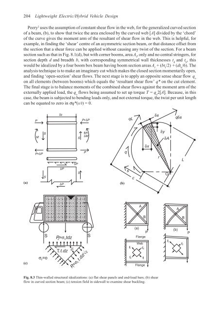
- Page 227 and 228: Design for optimum body-structural
- Page 229 and 230: ψ e 1.O σ av (a) (b) Design for o
- Page 231: Design for optimum body-structural
- Page 235 and 236: Design for optimum body-structural
- Page 237 and 238: Design for optimum body-structural
- Page 239 and 240: Design for optimum body-structural
- Page 241 and 242: Design for optimum body-structural
- Page 243 and 244: Design for optimum body-structural
- Page 245 and 246: Design for optimum body-structural
- Page 247 and 248: Design for optimum body-structural
- Page 249 and 250: Design for optimum body-structural
- Page 251 and 252: Design for optimum body-structural
- Page 253 and 254: Design for optimum body-structural
- Page 255 and 256: Design for optimum body-structural
- Page 257 and 258: Design for optimum body-structural
- Page 259 and 260: Design for optimum body-structural
- Page 261 and 262: Design for optimum body-structural
- Page 263 and 264: Design for optimum body-structural
- Page 265 and 266: Design for optimum body-structural
- Page 267 and 268: Design for optimum body-structural
- Page 269 and 270: Design for optimum body-structural
- Page 271 and 272: Design for optimum body-structural
- Page 273 and 274: Rolling resistance coefficient 0.03
- Page 275 and 276: Design for optimum body-structural
- Page 277 and 278: Design for optimum body-structural
- Page 279 and 280: 252 Lightweight Electric/Hybrid Veh