

STARLINE CATALOGUE Standard
STARLINE CATALOGUE Standard
STARLINE CATALOGUE Standard

You also want an ePaper? Increase the reach of your titles
YUMPU automatically turns print PDFs into web optimized ePapers that Google loves.
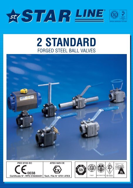
®APPROVAL CERTIFICATE N o . LRC 1600472 STANDARDFORGED STEEL BALL VALVESPED 97/23 ECATEX 94/9 CE0038Certificate N°: RPS 0160304/01Tech. File N° ST01 ATEXP-8871MAC/10699/2/TO/996D-0233
®CONSTRUCTION - MATERIAL19• Suggested materials after 2 years service• Empfonlene ersatzteile für 2 Jahres betrieb• Pièces de rechange conseillées pour 2 ans de service• Recambios aconsejados para 2 años de servico•• Suggested materials after 5 years service•• Empfonlene ersatzteile für 5 Jahres betrieb•• Pièces de rechange conseillées pour 5 ans de service•• Recambios aconsejados para 5 años de servicoBody shape for size* 1/4” to 3/4” Full Bore1/2” to 1” Reduced BoreBody shape for size** 1” to 1.1/2” Full Bore1.1/4” to 2” Reduced Bore<strong>STARLINE</strong>Figure No.ITEM••21• 3•• 4•• 56• 7• 8•• 9• 10• 1112131416••17• 1819ABQ.TY121211111221214124Part nameBezeichnungHandleHandhebelNutMutterPacking ringStopfbuchsenpackungSpring washerTellerfedemAntistatic stemAntistatische spindelGland packingDruck ringThrust washerSpindeldichtung«O» Ring stem«O» Ring spindelBallKugelSeatsSitzringBody sealGehäusedichtungBodyGehäuseEnd connectionsAnschlubstutzenStop-pinAnschlagBoltsGehäuseschraußeStop washerSicherungsscheißeBody sealGehäusedichtungNutsMutterFULL BOREREGULAR BOREDesignationComponentesLevierManetaEcrouTuercaGuarnitureJunta ejeRondelle ressortArandelaTige antistatiqueEje antiestaticoFouloirEstopadaRondelle butéeJunta ejeJoint toriqueTorica ejeSphèreEsperaSiègesAsientosJoint de corpsJunta cuerpoCorpsCuerpoEmboutTerminalesButéeTopeVisGoujonRondelle-freinArandela de seguridadJoint de corpsJunta de cuerpoEcrousTuercaN 123 SGVN 223 SGVA105/F316C.S. GalvanizedPlastic coverC.S. CadmiumPlatedGraphiteSpecial S.S.S.S. 316S.S. 316Reinf. PTFEVITONS.S. 316Reinf. PTFE “S”VITONASTM A105ASTM A105S.S. 304ASTM A193B7 GalvanizedS.S. 304Free AsbestosNA35ASTM A194-2HGalvanizedN 126 TGTN 226 TGTF316/F316C.S. GalvanizedPlastic coverS.S. 316GraphiteSpecial S.S.S.S. 316S.S. 316PTFEVITONS.S. 316PTFEPTFEA182 F316A182 F316LS.S. 304ASTM A193 B8S.S. 304Free AsbestosNA35ASTM A194-GR.8
®DIMENSIONSBSP Parallel: BS21 Rp - ISO 228/1 - ISO 7/1RpBSP Taper: BS21 Rc - ISO 7/1Rc - DIN 2999/1NPT: ANSI B1 20.1S.W.: ANSI B16.11- BS 5351Instruction for welding the valve on the line:With the valve in open position tack-weld in fourpoints on both ends. Lift-out the center piece andcomplete the welding. Insert the center piece andcontrol for easy operation.B.W.-P.E.: ANSI B16.25 Sch. 5S-10S-40-80-XSNote: other overall lenghts are available on request.Instruction for welding the valve on the line: with thevalve in open position tack-weld in four points on bothends. Lift-out the center piece and complete the welding.Insert the center piece and control for easy operation.WELDED NIPPLES: ANSI B36.10 B.W. - P.E.SCH. 40-80-XSNote: other overal lenghts are available on request.Instruction for welding the valve on the line: with thevalve in open position tack-weld in four points on bothends and then complete the welding without desmantlingthe valve.DNInchVALVESIZE81/4”FULL BOREDIMENSIONS mm / InchA A1 B C D752756715211.12.95 10.8 2.63 6 0.44WEIGHTkg/Lbs1.12.4ISO5211F03VALVESIZE--REDUCED BOREDIMENSIONS mm / InchA A1 B C D------- - - -WEIGHTkg/Lbs--ISO5211DNInch103/8”752.9527510.8672.63152611.10.4412.2F03DNInch151/2”752.9527510.8672.63152611.10.4412.2F03DNInch151/2”803.1528011702.75152614.20.561.32.8F03DNInch203/4”803.1528011702.75152614.20.561.32.8F03DNInch203/4”1003.9430011.8803.151937.5210.832.35F04DNInch251”1003.9430011.8803.151937.5210.832.35F04DNInchVALVESIZE251”FULL BOREDIMENSIONS mm / InchA A1 B C D1103109219325.44.33 12.2 3.62 7.5 1WEIGHTkg/Lbs3.27ISO5211F04DNInchVALVESIZE321.1/4”REDUCED BOREDIMENSIONS mm / InchA A1 B C D1103109219325.44.33 12.2 3.62 7.5 1WEIGHTkg/Lbs3.16.8ISO5211F04DNInch321.1/4”1204.7232012.61084.25225931.71.254.39.5F05DNInch401.1/2”1204.7232012.61084.25225931.71.254.29.2F05DNInch401.1/2”1405.5134013.41134.452259381.55.812.8F05DNInch502”1405.5134013.41134.452259381.55.512.1F05DIFFERENT CONFIGURATIONSEXTENDED STEM OVAL HANDLE LOCKING DEVICE “T” HANDLE
®AUTOMATIONHOW TO TRANSFORM A MANUAL OPERATED VALVE IN AUTOMATED VALVES1) Take out the handle nut2) Take out the handle3) For sizes: 1/4” - 3/8” - 1/2” F.B. or 1/2” - 3/4” R.B. handle nut is not to be fittedFor bigger sizes the handle nut has to be fittedTHE BELOW TABLE REFERS TO AIR TORQUE ACTUATORSVALVE SIZEFULL BORE RED. BOREInch1/4”3/8”1/2”3/4”1”1.1/4”1.1/2”DN8101520253240Inch-1/2”3/4”1”1.1/4”1.1/2”2”DN-152025324050A140.5140.5158.5158.5210.5210.5210.5B65656773738286DIMENSIONS (mm)C69698585102102102DOUBLE ACTING ACTUATORD20202020202020E2929363642.542.542.5F41.541.54747525252ACTUATORTYPEAT 051 DAISO F04-CH11AT 051 DAISO F04-CH11AT 101 DAISO F05-CH14AT 101 DAISO F05-CH14AT 201 DAISO F05/F07-CH14AT 201 DAISO F05/F07-CH14AT 201 DAISO F05/F07-CH14BRACKETTYPEST1ST1ST1ST2ST2ST3ST3ADAPTORTYPEA1/EA1/EA1/AA2/AA2/BA3/EA3/EVALVE SIZEFULL BORE RED. BOREInch DN Inch DNABDIMENSIONS (mm)CSPRING RETURN ACTUATORDEFACTUATORTYPEBRACKETTYPEADAPTORTYPEDIMENSIONS AND TORQUE TO SELECT ACTUATOR SUITABLE FOR <strong>STARLINE</strong> BALL VALVESInch1/4”VALVE SIZEDN8Inch-DN-mmM10x1mm5.5mm5.4DIMENSIONSFULL BORE RED. BORE A B C D ØE ØF ØGmm3.6mm25mm36mmM5x8ISO5211F03BREAKAWAYTORQUENm91/4”3/8”1/2”3/4”1”1.1/4”1.1/2”8101520253240-1/2”3/4”1”1.1/4”1.1/2”2”-152025324050158.5158.5210.5210.5247.5268.5268.565656773738286858510210211512712720202020202020363642.542.549.556564747525256.86767AT 101 S10ISO F05-CH14AT 101 S10ISO F05-CH14AT 201 S10ISO F05/F07-CH14AT 201 S10ISO F05/F07-CH14AT 251 S10ISO F05/F07-CH17AT 301 S10ISO F05/F07-CH17AT 301 S10ISO F05/F07-CH17ST1ST1ST1ST2ST2ST3ST3A1/AA1/AA1/AA2/AA2/EA3/AA3/A3/8”1/2”3/4”1”1.1/4”1.1/2”1015202532401/2”3/4”1”1.1/4”1.1/2”2152025324050M10x1M10x1M12x1.25M12x1.25M15x1.5M15x1.55.55.57.57.58.98.95.4*BREAK AWAY TORQUE AT MAX. WORKING PRESSURE WITH SEATS TYPE PTFE + 25% C. GRAPHITE ‘S’FOR SEATS IN VIRGIN PTFE ‘T’ -5%.CONVERSION FACTORS: 1Nm= 0,7376 Lb-in / 1 Ib.ft.= 1.365 Nm / 1 Nm= 8,86 Lb-in651014143.63.69101314252530303535363642425050M5x8M5x8M5x8M5x8M6x10M6x10F03F03F04F04F05F0591218253035General Remarks:1) The above actuators have been selected considering an air supply of 80 psi or 5,6 bar.2) On spring return actuators teh N. of spring per side is 5.3) For different air supply please see Air Torque Catalogue.4) Bracket and adaptor are dimensioned to fit Air Torque actuators.5) When air supply for actuator is lower than 5,6 bar bigger actuator must be selected andbracket plus adaptor become specialIt must be understood that many factor can influence the torque of ball valves in field service. For this reason to SELECT PROPER ACTUATOR it must be used the “TORQUE ADJUST-MENT FACTORS” table no. A003/94.NET BREAK AWAYTORQUE OF VALVESPROCESSFREQUENCE OFPROCESSVALVE SEATINGSUGGESTED+ + + + + =MEDIAOPERATIONTEMPERATUREMATERIALSAFETY FACTORTORQUE TO SELECTACTUATOR OR GEAR IN NM“<strong>STARLINE</strong>” BRACKETS ISO 5211 IN STAINLESS STEELTYPE OFBRACKETST1ST2DIMENSIONS (mm)A B C D D1 d d1353548.548.536.54042-505036426-7766ISO5211F03/F04-F05F04/F05ST33948.548.5505077F05/F05ST354565.548.5705097F05/F07ST44565.565.5707099F07/F07ST55692921021021111F10/F10
®TECHNICAL DATADESCRIPTIONCONSTRUCTION : THREE PIECES BOLTED CONSTRUCTION - SOLID BALL - ANTI BLOW OUT PROOF STEM DESIGNSOFT SEATS - ANTISTATIC DEVICE - ISO 5211 ON THE TOP FOR EASY AUTOMATION.SIZE: DN 8 ÷ 40 FULL BORE -- DN 15 ÷ 50 REDUCED BORE1/4” ÷ 1.1/2” FULL BORE -- 1/2” ÷ 2” REDUCED BORECLASS: PN 16 ÷ 100 or ASME 150 ÷ 800 LBS or 1000 ÷ 2000 WOGTEMPERATURE : -100°C UP TO + 260°CMATERIAL: ASTM A105 - 316 - 316LDESIGN: ASME B16.34 - ASME B31.1 - BS5351 - P.E.D. 97/23/EC - ATEX 94/9 CEMARKING: MSS SP25CE 0038: ACCORDING TO DIRECTIVE 97/23/CE - MODULE H CATEGORY III - NOTIFIED BODY LLOYD’S REGISTEREDCERTIFICATE NR. RPS 01060304/01Ex IM2/II 2GD : ACCORDING TO ATEX 94/9 CE - TECHNICAL FILE NR. ST01 ATEXTEST CERTIFICATE : UNI EN 10204 TYPE 3.1B UNLESS OTHERWISE REQUIREDSERVICES: FOR GENERAL SERVICES AND CHEMICAL INDUSTRIESPRESSURE/TEMPERATURE LIMITATIONS OF SEAT SEALS-B 1/4" to 1/2" F.B. 1/2" to 3/4" R.B.R 1/4" to 1/2" F.B. 1/2" to 3/4" R.B.T 1/4" to 1/2" F.B. 1/2" to 3/4" R.B.S-B 3/4" to 1" F.B. 1" to 1.1/4 R.B.R 3/4" to 1" F.B. 1" to 1.1/4 R.B.T 3/4" to 1" F.B. 1" to 1.1/4" R.B.S-B 1.1/4" to 1.1/2" F.B. 1.1/2 to 2" R.B.R 1.1/4" to 1.1/2" F.B. 1.1/2" to 2" R.B.T 1.1/4" to 1.1/2" F.B. 1.1/2" to 2" R.B.MAXIMUM WORKING PRESSURE (WOG/CWP)VALVESIZESEATMATERIALVALVESIZESEATMATERIALFULL BOREREDUCED BOREReinforced PTFE(S-B)Reinforced PTFE(R)Virgin PTFE(T)CLASS RATINGFULL BOREREDUCED BOREReinforced PTFE(S-B)Reinforced PTFE(R)Virgin PTFE(T)PsiBarPsiBarPsiBar1/4” 3/8” 1/2” 3/4” 1” 1.1/4” 1.1/2”1/2” 3/4” 1” 1.1/4” 1.1/2” 2”2580 2580 2580 2320 2320 2060 2060178 178 178 160 160 142 1422350 2350 2350 2030 2030 1860 1860162 162 162 140 140 128 1282250 2250 2250 2000 2000 1800 1800155 155 155 138 138 124 1241/4” 3/8” 1/2” 3/4” 1” 1.1/4” 1.1/2”1/2” 3/4” 1” 1.1/4” 1.1/2” 2”150 ÷ 800150 ÷ 800150 ÷ 800150 ÷ 600150 ÷ 600+°C+°FSEAT MATERIALS“T” = PTFE Virgin“R” = PTFE + 15% Fiberglass“S” = PTFE + 20% C. 5% Graphite“B” = PTFE +60% BronzeFLOW DATAThe following flow rates were determined for ball valves in fully open position and a water temperature of 60°F (15°C).Kv value is the full capacity flow rate through the ball valve in cubic metres per hour (m 3 /h) with a pressure drop of 1 bar.Cv value is the full capacity flow rate through the ball valve in gallons/min. of water at 60°F with a pressure drop of 1 psi.REDUCED BOREVALVE – 1/2” 3/4” 1” 1.1/4” 1.1/2” 2”SIZE – 15 20 25 32 40 50Cv 8 13 32 48 82 120KV 6,8 11 27,5 41 70 103FULL BOREVALVE 1/4” 3/8” 1/2” 3/4” 1” 1.1/4” 1.1/2”SIZE 8 10 15 20 25 32 40Cv 8 8 12 30 45 78 115KV 6,8 6,8 10 26 38 67 99


