ENFORCER - SECO-LARM
ENFORCER - SECO-LARM
ENFORCER - SECO-LARM

Create successful ePaper yourself
Turn your PDF publications into a flip-book with our unique Google optimized e-Paper software.
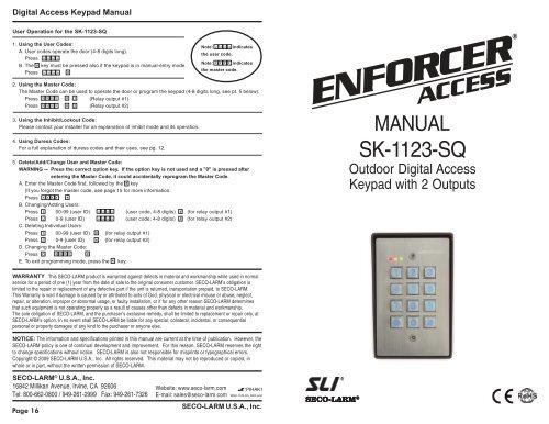
Digital Access Keypad ManualUser Operation for the SK-1123-SQ1. Using the User Codes:A. User codes operate the door (4-8 digits long).Press u u u uB. The # key must be pressed also if the keypad is in manual-entry mode.Press u u u u #Press X X X X # 1 (Relay output #1)X X X X # 2Note: u u u u indicatesthe user code.Note: X X X X indicatesthe master code.2. Using the Master Code:The Master Code can be used to operate the door or program the keypad (4-8 digits long, see pt. 5 below).Press (Relay output #2)3. Using the Inhibit/Lockout Code:Please contact your installer for an explanation of inhibit mode and its operation.4. Using Duress Codes:For a full explanation of duress codes and their uses, see pg. 12.5. Delete/Add/Change User and Master Code:WARNING -- Press the correct option key. If the option key is not used and a "0" is pressed afterentering the Master Code, it could accidentally reprogram the Master Code.A. Enter the Master Code first, followed by the key*(If you forgot the master code, see page 15 for more information.Press X X X X*B. Changing/Adding Users:Press 1 00-99 (user ID) u u u u (user code, 4-8 digits) # (for relay output #1)Press 2 0-9 (user ID) u u u u (user code, 4-8 digits) # (for relay output #2)C. Deleting Individual Users:Press 1 00-99 (user ID) # (for relay output #1)Press 2 0-9 (user ID) # (for relay output #2)D. Changing the Master Code:Press 0 X X X X #E. To exit programming mode, press the key.*WARRANTY This <strong>SECO</strong>-<strong>LARM</strong> product is warranted against defects in material and workmanship while used in normalservice for a period of one (1) year from the date of sale to the original consumer customer. <strong>SECO</strong>-<strong>LARM</strong>’s obligation islimited to the repair or replacement of any defective part if the unit is returned, transportation prepaid, to <strong>SECO</strong>-<strong>LARM</strong>.This Warranty is void if damage is caused by or attributed to acts of God, physical or electrical misuse or abuse, neglect,repair, or alteration, improper or abnormal usage, or faulty installation, or if for any other reason <strong>SECO</strong>-<strong>LARM</strong> determinesthat such equipment is not operating properly as a result of causes other than defects in material and workmanship.The sole obligation of <strong>SECO</strong>-<strong>LARM</strong>, and the purchaser’s exclusive remedy, shall be limited to replacement or repair only, at<strong>SECO</strong>-<strong>LARM</strong>’s option. In no event shall <strong>SECO</strong>-<strong>LARM</strong> be liable for any special, collateral, incidental, or consequentialpersonal or property damages of any kind to the purchaser or anyone else.NOTICE: The information and specifications printed in this manual are current at the time of publication. However, the<strong>SECO</strong>-<strong>LARM</strong> policy is one of continual development and improvement. For this reason, <strong>SECO</strong>-<strong>LARM</strong> reserves the rightto change specifications without notice. <strong>SECO</strong>-<strong>LARM</strong> is also not responsible for misprints or typographical errors.Copyright © 2009 <strong>SECO</strong>-<strong>LARM</strong> U.S.A., Inc. All rights reserved. This material may not be reproduced or copied, inwhole or in part, without the written permission of <strong>SECO</strong>-<strong>LARM</strong>.<strong>ENFORCER</strong>MANUALACCESSSK-1123-SQOutdoor Digital AccessKeypad with 2 Outputs®<strong>SECO</strong>-<strong>LARM</strong> ® U.S.A., Inc.16842 Millikan Avenue, Irvine, CA 92606Tel: 800-662-0800 / 949-261-2999 Fax: 949-261-7326Page 16Website: www.seco-larm.comE-mail: sales@seco-larm.com®PIHAK1MiSK-1123-SQ_0905.pmd<strong>SECO</strong>-<strong>LARM</strong> U.S.A., Inc.<strong>SECO</strong>-<strong>LARM</strong> ®
TABLE OF CONTENTSIntroduction ................................................................................................................ 2Dimensions ................................................................................................................ 2Unique features ......................................................................................................... 3Wiring - Basic diagram .............................................................................................. 4Specifications ............................................................................................................ 5Wiring -- Example, with inhibit control authorized ................................................... 6Wiring -- Example, with connection to lock device and alarm arm/disarm ............. 7List of user codes worksheet .................................................................................... 8,9Wiring -- Mantrap using two keypads ...................................................................... 10Wiring -- Auxiliary accessories ................................................................................ 11Programming notes ................................................................................................... 12LED and buzzer indicators ........................................................................................ 12Preparing to Program, Getting Started, and User programming .............................. 13Installer programming ............................................................................................... 14Reprogram the keypad (certain data) ....................................................................... 15Reprogram the keypad (complete data refresh) ....................................................... 15Delete user ................................................................................................................ 15Master code bypass (DAP jumper) ........................................................................... 15User operation ........................................................................................................... 16INTRODUCTIONThe SK-1123-SQ is the ideal keypad for office, commercial, and home security installations. This self-containedsecurity keypad has a built-in 5-Amp relay output and a 1-Amp relay output for maximum flexibility whenconnecting to electronic door strikes, door alarms, door chimes, alarm control panels, or other security andaccess control applications. The outputs can be programmed for timed (1-999 seconds) or ON/OFF operation.The SK-1123-SQ can be programmed for up to 100 4-digit to 8-digit user codes for the primary output, and upto 10 4-digit to 8-digit user codes for the second output. All programming and code information is stored in nonvolatileEEPROM memory to protect the data in case of power loss.DIMENSIONS4 15 /16"(125mm)3 1 /8"(78mm)7 8 93 1 /4"(82.5mm)2"(51mm)1 13 /16"(45mm)4 5 /8"(118mm)PARTS LISTKeypad x 1Back box x 1Diode x 1Installation screws x 3Mounting screws x 2Security wrench x 1REPROGRAM THE KEYPAD (CERTAIN DATA)To change certain data in the keypad (such as to delete or change user codes), do the following:1. Enter program mode by keying in the master code and the * key:X X X X*The keypad is now in the programming mode.2. Use the programming instructions on page 13 and 14 to make any changes to the keypad's data.3. Exit the programming mode by pressing the*key.REPROGRAM THE KEYPAD (COMPLETE DATA REFRESH)Sometimes it may be necessary to completely erase all current data (except the master code) and input new data. An example ofwhen this may be necessary is the sale of a protected building to a new owner. In such a situation, do the following:1. Enter the programming mode by keying in the master code and the*key, then enter the refresh code, 8 9 0 1and the #X X X Xkey:*The keypad is now in the programming mode.8 9 0 1 # All old data is cleared and the keypad is ready for new data.NOTE: The master code does NOT change.2. Use the programming instructions on pages 13 and 14 to enter the keypad's data.3. Exit the programming mode by pressing the key.DELETE USERTo delete a user who has left the company or who no longer has authority to enter the protected area:1. Enter program mode by keying in the master code and the key:*X X X X* The keypad is now in the programming mode.2. Enter the output #, user ID number, and the # key:To delete user ID 05 from output #1, press 1 0 5 # .To delete user ID 1 from output #2, press 2 1 # .3. Exit the programming mode by pressing the key.*MASTER CODE BYPASS (DAP jumper)If the master code is forgotten or does not work, use the DAP (direct access to program) jumper to override theforgotten code and permit direct entry into the programming mode as follows:1. Disconnect the power supply.2. Move the DAP jumper from OFF to ON.<strong>SECO</strong>-<strong>LARM</strong>3. Reconnect the power supply.®SK-1123-SQThe keypad will start beeping.4. Move the DAP jumper back to the OFF position.The keypad will stop beeping as soon as thejumper is removed.5. The keypad is now in the programming mode,ready to receive new programming data.6. Re-program the keypad as shown startingon page 13.NOTE -- A new master code may be programmed toreplace the one that was lost or forgotten. Note that theRelaysequence for replacing the old master code is as follows:1Option* Key in new code Confirm Exit0 X X X X#**Zero "0" is for new master code only; see page 13 for other options.*(+) (--)12-24V AC/DCOutput #1N.C. COM N.O.Relay2Output #2N.C. COM N.O.TamperON OFFDAPInterlock TamperN.C.O/P 1InhibitDoorSensor(--)GroundDuressOutputKeypadActiveEgressInAttachmentScrewPage 2 Page 15
Digital Access Keypad ManualDigital Access Keypad ManualINSTALLER PROGRAMMINGThese functions should only be used by professional installers, as incorrect entries can disable the entire keypad function.Enter Programming ModeEnter Master code ConfirmX X X X **Key in the Master Code.*Note: For first-time use, Master code is 0 0 0 0Data RefreshOption Confirm Function8 9 0 1 # Clears all previously stored data.Configure Relay OutputsOption Output time4 0 1 to 9994 15 0 1 to 9995 1Wrong Code LockoutOption # of tries7 07 17 2 5 to 107 6 0 08 010Confirm######User Code Entry ModeOption Code entry1Confirm#8 28 39*010#####Confirm####Door Forced-Open AlarmOption Code entry Confirm Function{FunctionEnter into programming mode(DEFAULT: 0 0 0 0 )(DEFAULT: Momentary, 1-sec. output for both outputs)FunctionRelay #1, momentary mode, from 1 to 999 secondsRelay #1, shunt mode (ON/OFF)Relay #2, momentary mode, from 1 to 999 secondsRelay #2, shunt mode (ON/OFF)(DEFAULT: 10 tries / 30 seconds)FunctionAfter 10 successive wrong codes, 30-second lockoutAfter 10 successive wrong codes, Duress activatedAfter 5 to 10 wrong codes, 15-min. lockout - Can reset with Master CodeNone of the aboveDoor forced-open alarm is enabledDoor forced-open alarm is disabledOutput Activation Announcer(DEFAULT: On)Option Code entry Confirm Function1# 1-sec. beep notifies the user to open the door when the output relay is activated with theuser code or egress button. Use with a locking device which gives no sound when it8 1{activates, such as a magnetic lock.0# The beep is disabled, replaced by 2 short beeps for valid user codes.{Keypress BeepsOption Code entry Confirm Function{Door Propped Open Alarm TimerOption Code entry Confirm Function0{1 to 999(DEFAULT: Manual)FunctionAuto Entry Mode is selected. The # key that follows the user code is NOT required incode entry. The User Codes MUST be set to the same digit length as the Master Code,from 4-8 digits.Manual Entry Mode is selected. The # key that follows the user code is required incode entry. The User Codes can be 4-8 digits, but not necessarily all of the same length.Keypad beeps when a key is pressed.Silent operation -- keypad does not beep when a key is pressed.No door propped open alarmAllowable time from 1 to 999 seconds that the door can be left open before the doorpropped open alarm startsExit Programming ModeConfirm FunctionExits programming mode, returns keypad to normal operations(DEFAULT: Disabled)(DEFAULT: On)(DEFAULT: Off)UNIQUE FEATURES• 12-24V AC/DC universal power -- No programming or jumpers needed.• Mantrap -- Each keypad can be used as a stand-alone keypad. However, the mantrapfeature uses two keypads to protect an area with two doors by ensuring that only onedoor is open at a time. With the mantrap interlock functions, when a user keys in thecode to open one door, a signal is sent to disable the second keypad, therebypreventing access through the second door until the first door is closed.• Relay output #1 inhibit control -- Relay output #1 is typically used for a door strike.If the keypad is set to the "inhibited" mode, relay output #1 will not operate. Thisincreases the security of the protected premises during the time it is not expected tobe occupied, such as during evening or weekend hours. An authorized user canenable or disable the inhibit control by using the code for relay output #2 at any time,depending on how installed.• Door forced open warning -- When used with an optional magnetic contact, thekeypad beeps continuously if the door to the protected premises is forced openwithout using a valid user code. The warning can be stopped only by closing theprotected door.• Door propped open warning -- When used with an optional magnetic contact, thekeypad beeps continuously if the door is propped open after the allowed open time.The allowable open time is programmable. The warning stops when the door is reclosed.• Auto or manual code entry checking:• Auto code entry checking mode -- When all the user codes have the same numberof digits, the keypad will activate automatically when the code is entered. There isno need to press the "#" key. This is convenient for the users.• Manual code entry checking mode -- The user codes can vary in number of digits,and the user must press the "#" key when finished entering the code. Thisincreases security.• Keypad active output -- This NPN transistor open collector ground (-) outputactivates for 10 seconds when any key on the keypad is pressed. This can be used totrigger a video recorder or turn on a light, or to signal a guard that someone isentering the protected premises.• Door auto relock -- The keypad will relock an open door either when the relock timeexpires or immediately after the door is closed, depending on which occurs first. Thisprevents unwanted "tailgate" entries, which can happen if an unauthorized persontries to follow an authorized person through the door.• Duress output -- This NPN transistor open collector ground (-) output can be used totrigger a silent alarm if an authorized user is forced under duress to use the keypad.The duress output is activated by adding 2 to the first digit of user code 1. In thiscase, the protected door opens as it would normally, but a signal is quietly sent to aremote device to call for help without alerting the unauthorized person.• Backlit keypad -- The keypad is backlit to increase nighttime visibility. Forconvenience, the lighting intensity will increase for 10 seconds after any key ispressed.Page 14 <strong>SECO</strong>-<strong>LARM</strong> U.S.A., Inc.Page 3
Digital Access Keypad ManualDigital Access Keypad ManualWIRING, BASIC DIAGRAM(+) (--)12-24V AC/DCRelay1Output #1N.C. COM N.O.Relay2Output #2N.C. COM N.O.TamperON OFFDAPTamperN.C.InterlockO/P 1InhibitDoorSensor(--)GroundDuressOutputKeypadActiveEgressInN.C. TamperN.C. Tamper}N.C. dry contact.50mA max.Interlock -- NPN transistor, used with second keypad 1(-) N.O. O/P #1 inhibit 2(-) N.C. Door position sensor input(-) Common Ground - for use with interlock functionDuress O/P -- Transistor Ground (-) 100mA@24VDCKeypad Active O/P -- Transistor Ground (-) 100mA@24VDCPREPARING TO PROGRAM THE KEYPADTo program the SK-1123-SQ, first determine the following information:1. The master code -- Allows the system administrator to program or operate the keypad.2. The user code or codes -- Allows users to use the keypad's functions.3. Configuration of the relays and outputs -- For relay output #1 and relay output #2, determine whetherthe output should operate from 1 to 999 seconds and then turn OFF (momentary mode), or turn ON/OFF via the code (shunt mode).4. Result of improper code entry (optional) -- Choose between a 30-second code lockout, duress output,a 15-minute code lockout, or no reaction.* Note: When X X X X appears in the instructions, it indicates master code entry.GETTING STARTEDA master code is required to program the keypad. The default master code is set to "0000." To change aforgotten master code, go to page 15 and follow the instructions for "MASTER CODE BYPASS" (DAPjumper).Once the master code is set, review the programming options and decide exactly what the keypad will do,including the format of the user access codes as well as how the keypad responds via the relay output,buzzer and LEDs. Note that in every case the basic steps for programming are:1. Enter the master code, followed by the * key, which puts you in programming mode.2. Enter the programming options defined in the various sections as needed, followed by the # key.3. Enter the * key again to exit programming mode.Note: A rapid string of 5 beeps and/or 5 LED flashes indicates an error, while 2 beeps indicates that theentry has been accepted.EG In - Egress -- N.O., ground (-) 3Relay #2 output -- N.O.}1ARelay #2 output -- COMRelay #2 output -- N.C.Relay #1 output -- N.O.}5ARelay #1 output -- COMRelay #1 output -- N.C.(-)12~24}(+) VAC/VDC 4@ 28VDC, Normallyclosed and normally opendry contacts@ 28VDC, Normallyclosed and normallyopen dry contacts1Mantrap control output -- Outputs ground (-) for five seconds after relay output #1 is activated, continues while the door is open.2Connect to ground (-) to prevent relay output #1 from operating, or to the mantrap (interlock) control output of another keypadto disable output #1 while the other keypad is active.3Connect to optional N.O. push button or switch.4For DC, connect to a regulated power supply with correct polarity, + to +, - to -. For AC, polarity is not important.USER PROGRAMMINGENTER PROGRAMMING MODEEnter Master codeConfirmX X X X*Note: For first-time use, Master code is 0 0 0 0ADDING OR CHANGING MASTER AND USER CODESOption012User ID00 to 990 to 9Access code4 to 8 digits4 to 8 digits4 to 8 digitsConfirm###FunctionEnter into programming modeWARNING -- Press the correct option key. If the option key is not used and a "0" is pressed after entering the MasterCode, it could accidentally reprogram the Master Code.FunctionChange Master CodeSet/change up to 100 User Codes for relay output #1, with duress featureSet/change up to 10 User Codes for relay output #2Note: No user code may be the same as the master code.Note: For User ID, key in the number of the user. For Access Code, type in the code for that particular user.DELETE A USERTo delete a user who has left the company or who no longer has authority to enter the protected area:1. Enter programming mode:Enter Master code Confirm FunctionX X X X2. Delete code:*Enter into programming modeOption User ID Confirm Function1 00 to 99 # Deletes specific user ID from output #120 to 9# Deletes specific user ID from output #2EXIT THE PROGRAMMING MODE BY PRESSING THE "* " KEYPage 4 <strong>SECO</strong>-<strong>LARM</strong> U.S.A., Inc.Page 13
Digital Access Keypad ManualDigital Access Keypad ManualPROGRAMMING NOTES1. Master Code: The SK-1123-SQ comes pre-programmed with the Master Code set at 0000. Additional codes and/ordata should be programmed at the owner's discretion. However, to ensure security, program a new personal MasterCode to replace the factory-set Master Code as soon as possible.2. Factory defaults:__________________________________________________________Master code 0000__________________________________________________________User code length4-8 digit__________________________________________________________Main relay output time 1 second__________________________________________________________Auxiliary relay output time 1 second__________________________________________________________Wrong code lockout 10 tries / 30 sec.LED INDICATORS• Red LED -- Lights while output #2 is activated.• Amber LED -- Flashes to show the keypad status (see below).• Green LED -- Lights while output #1 is activated.BUZZER AND LED SIGNALSThe keypad's built-in buzzer and the amber LED can signal the following:Door forced open alarm disabled ___________________________________________________________Output activation announcer ON__________________________________________________________User code entry mode manual__________________________________________________________Keypress beepON__________________________________________________________Door propped open alarm OFFSilent operationOFF3. Code operation: User codes are each four to eight digits and are assigned to two-digit IDs. If all the codes have thesame number of digits, the keypad can be programmed for whether the # key must be used or not after entering thecode (see programming, option 82, page 14).The administrator can easily delete the code of one user via the two-digit ID, if the user is no longer authorized toenter a protected area, without the need to teach the new code to all the other users.Relay output #1 allows up to 100 user codes, and relay output #2 allows up to 10 user codes.4. Using Duress Codes (Relay #1 only): Duress codes are used to activate a separate device silently to alert a guardor other personnel that a user is operating the keypad under threat. The keypad operates as normal, but a signal issent to alert others.Duress codes do not need to be programmed. All user codes are automatically turned into duress codes byincreasing the first digit of a user code by the number 2. The code is entered the same way as a regular user code.For example:User code 4468 can be entered as duress code 6468User code 9843 can be entered as duress code 1843User code 8181 can be entered as duress code 0181NOTE: If a user code is programmed, its duress code is unique and cannot be programmed as another usercode. For example:If user code 4468 is programmed, its duress code of 6468 is automatically programmed. A user code of 6468 cannotbe programmed.Note: Once activated, the duress output continues until a correct user code is entered._____________________________________________________________________________________STATUSBUZZER TONES* AMBER LED FLASHES_____________________________________________________________________________________1. In programming mode - - -ON_____________________________________________________________________________________2. Successful key entry 1 beep1 flash_____________________________________________________________________________________3. Successful code entry 2 beeps2 flashes_____________________________________________________________________________________4. Unsuccessful code entry 5 beeps5 flashes_____________________________________________________________________________________5. DAP jumper not replaced Continuous beeps Continuous flashes_____________________________________________________________________________________6. In standby mode- - -1 flash in 2-sec. intervals7. Output relay activated 1-sec. long beep** - - -SPECIFICATIONSPower:• Operation voltage -- 12-24 Volts AC/DC. No jumper needed to set voltage.• Stand-by current drain -- 15mA @12VDC.• Active current drain (press keypad key) -- Under 45mA@12VDC.• Active current drain (one relay activated) -- Under 80mA@12VDC.• Active current drain (two relays activated) -- Under 130mA@12VDC.Outputs:• Relay output #1 -- 5A @ 28VDC, Form "C", N.O./C./N.C., programmable for 1 to 999 second timedoutput or shunt (start/stop) output. Three terminals.• Relay output #2 -- 1A @ 28VDC, Form "C", N.O./C./N.C., programmable for 1 to 999 second momentaryoutput or shunt (start/stop) output. Three terminals.• Tamper output -- 50mA @ 12VDC, N.C. output. Connect to tamper circuit of alarm control panel.Two terminals.• Keypad active or alarm output -- Transistor ground max. 100mA @ 24VDC. Switches to ground (-) for 10sec. when a key is pressed (keypad active output), or switches to ground (-) to indicate a door was forcedopen or propped open (alarm output). Single terminal.• Mantrap (interlock) control output -- Outputs ground (-) for five seconds after relay output #1 is activated,continues while the door is open. Use to disable a second keypad during this time. Single terminal.• Ground output -- Steady ground (-), 100mA @ 24VDC. Single terminal.• Duress output -- Transistor ground (-), 100mA @ 24VDC. If switches to ground (-) after the duress codeis entered. Single terminal.Inputs:• Power -- 12-24Volts AC/DC. Two terminals.• Egress -- N.O., ground (-). Single terminal.• Door sensor input -- N.C., ground (-). Connect to an N.C. magnetic contact to show if door is opened orclosed, or connect to ground (-) if not used. Single terminal.• Relay output #1 disable input -- Connect to ground (-) to prevent relay output #1 from operating, or to themantrap (interlock) control output of another keypad to disable output #1 while the other keypad is active.Single terminal.Code Operation:• Auto or manual code entry. Up to 100 user codes for relay output #1, up to 10 user codes for relayoutput #2. 111,110,000 possible user code combinations.Auto refresh time during code entry:• Max. 10 seconds to enter each digit.• Max. 30 seconds to enter each code.Dimensions (keypad with back box):• 4-15/16" x 3-1/8" x 2" (125 x 78 x 51 mm).Weight• 18 oz. (510 grams).NOTE: * The buzzer can be disabled through programming option 83, ref. pg. 14.** The output relay activated beep can be disabled through programming option 81, ref. pg. 14.Page 12 <strong>SECO</strong>-<strong>LARM</strong> U.S.A., Inc.Page 5
Digital Access Keypad ManualDigital Access Keypad ManualWIRING:Example Wiring, with Inhibit Control AuthorizedWIRING:Auxiliary AccessoriesCONNECTIONING INHIBITAUTHORIZATION CONTROLWARNING• For safety, ensure that noone is inside the premisesbefore starting the doorlock inhibit function.During inhibit, doorsremain locked.Interlock TamperN.C.O/P 1InhibitDoorSensor(--)GroundDuressOutputKeypadActiveTAMPER N.C.DURESS OUTPUTDuressOutputTamperN.C.(-)GroundA<strong>LARM</strong>CONTROLPANEL24-hour N.C.protectionzoneA<strong>LARM</strong>CONTROLPANEL12~24VAC/DCpowersupply+--ST-UV12-S1.0QEgress button(Inside premises)N.O.Additional egressbuttons can be N.O.connected in parallel(+) (--)12-24V AC/DC--------------------------------------------Output #1N.C. COM N.O.N.C. N.O.OROutput RelayN.O. Output forFail-secure lockN.C. Output forFail-safe lockElectricLock-- +1N4004Output #2N.C. COM N.O.EgressInCathodeNote: If inhibit controlis activated, the duressoutput is disabled.• Connect a 1N4004 diode as close as possible to and in parallel with the DC-powered electromagnetic or electric lock.This absorbs possible electromagnetic interference to prevent operation of the lock from damaging the keypad. A1N4004 is not required for AC-powered locks.• Connect the ground (-) terminal of the keypad to earth to prevent electrostatic discharge from damaging the keypad.• The connection of relay output #1 disable to output #2, as shown above is optional. When so wired, output #2 is theinhibit control. To use, program output #2 for shunt on/off operation. When output #2 is ON, relay output #1 will notwork. For example, this can be used to prevent users from entering the protected premises during the evening orweekend. See programming option 61.• The green LED lights while relay output #1 is activated to activate the lock.• The red LED lights to show that relay output #1 is disabled by the activation of output #2.• Tape all unused wires to prevent short circuits.WARNING:• If the inhibit control is used, all personnel must exit the protected premises before output #2 is activated. Otherwise,personnel in the protected premises will not be able to exit until output #2 is turned OFF.• The user code for output #2 in this case should be given only to personnel authorized to enter the premises any time.It should not be given to other users.DOOR SENSINGDoorSensing24-hour N.O.protection zone,max. 100mAKEY ACTIVE or A<strong>LARM</strong> OUTPUTKeypadActive(-)Ground1.5kLED+12VLowpowerpiezobuzzerORMAGNETICDOORCONTACT(N.C.)SM-200Required for:• Door Auto Relock• Door Forced-open Alarm• Door Propped-open Alarm• Mantrap (Interlock) Control+12VIsolationrelayN.O. relaycontactRELAY OUTPUT #2 -- Example, to shunt an alarm N.C. zoneN.C. COM N.O.Output #2KeypadActiveN.C.N.C. magnetic contactSM-200To protection zone of analarm control panelThe Key Active Output will switch to ground(-) for 10 seconds whenever a key istouched. Use to turn ON an LED and/or asmall buzzer to notify a guard, or to energizea relay to switch ON lights or CCTV camera.Only one connection option is recommended.Make sure the current sink does not exceedthe maximum rating of 100mA.An external power supply and isolation relayare necessary to drive high power devicessuch as lights or CCTV cameras.Use Normally Open (N.O.) outputremove to shunt a Normally Closed(N.C.) protection zone of an alarmsystem.Set relay output #2 to Start / Stop mode(programming option 51)Page 6 <strong>SECO</strong>-<strong>LARM</strong> U.S.A., Inc.Page 11
Digital Access Keypad ManualWIRING:Example Wiring, 2 Keypads with MantrapWIRING:Example Wiring, with Connection to Lock Device and Alarm Arm/DisarmDigital Access Keypad ManualDOOR #1 DOOR #2Interlock TamperN.C.Cross wire connection for interlock functionsInterlock TamperN.C.REMARKSOutput relay #1N.O. output for fail-secure lockN.C. output for fail-safe lockInterlock TamperN.C.O/P 1InhibitO/P 1InhibitO/P 1Inhibit(--)GroundDoorSensor12~24VAC/DCpowersupply+--ST-UV12-S1.0Q(+) (--)12-24V AC/DCOutput #1N.C. COM N.O.N.C. N.O.ORKeypad Duress (--) DoorActive Output Ground SensorOutput #2 EgressN.C. COM N.O. InN.C.Door #1sensingSM-20012~24VAC/DCpowersupply+--ST-UV12-S1.0QCommon ground(+) (--)12-24V AC/DCOutput #1N.C. COM N.O.N.C. N.O.ORKeypad Duress (--) DoorActive Output Ground SensorOutput #2 EgressN.C. COM N.O. InN.C.Door #2sensingSM-20012~24VAC/DCpowersupplyST-UV12-S1.0Q+--(+) (--)12-24V AC/DCOutput #1N.C. COM N.O.N.C. N.O.OROutput #2N.C. COM N.O.Keypad DuressActive OutputEgressInA<strong>LARM</strong> CONTROL PANELN.O. Duress -- To 24-hour N.O. zoneCom gnd (--) of keypad & alarm systemRelay output #2Alarm arm/disarm control --Consult}(--)N.C.N.O.alarm system manual for howCOM to connect for N.C. or N.O. operationTamper --N.C. To a 24-hour N.C. zone}Egress button(Open door #1from inside)N.O.ElectricLock #1-- +1N4004CathodeEgress button(Open door #2from inside)N.O.ElectricLock #2-- +1N4004CathodeEgress button(Inside premises)Additional egressbuttons can beconnected in parallelN.O.------------------------N.O.-------------ElectricLock-- +1N4004 CathodeInterlock -- Each keypad can be used as a stand-alone keypad. The mantrap feature is for a protected area withtwo doors to ensure only one door is open at a time. With the mantrap feature, when a user keys in the code toopen one door, a signal is sent to the second keypad to disable it, thereby preventing access through the seconddoor until the first door is closed.Note: PLEASE ALSO REFER TO THE NOTES ON PAGE 6 FOR MORE GENERAL INFORMATION.• Use an N.C. magnetic contact or some other N.C. device to detect whether a door is opened or closed. Do thisfor the two entrances to the protected premises.• Combine this wiring diagram with the diagram on page 7 if connection to an alarm control panel is required.• Connect output #2 to relay output #1 disable as shown on page 6 if inhibit control is required.• To use the mantrap feature:o Use either the keypad from outside or the egress button from inside the protected premises to open one ofthe two doors.o While the first door is opened, the first keypad sends a signal to the second keypad to prevent the secondkeypad from being used to open the second door.o After the first door is closed, both keypads are ready to use.Note:PLEASE ALSO REFER TO THE NOTES ON PAGE 6 FOR MORE GENERAL INFORMATION.• The electromagnetic or electric door lock operation is the same as page 6.• Relay output #2 controls the arm/disarm of the alarm control panel. Consult the alarm control panel manual for moreinformation.• Connect the duress output to a 24-hour N.O. zone and the tamper output to a 24-hour N.C. zone on the alarm controlpanel.• The keypad's terminal ground (-) connects to the ground (-) wire of the alarm control panel to enable the two to worktogether.Page 10 <strong>SECO</strong>-<strong>LARM</strong> U.S.A., Inc.Page 7