You also want an ePaper? Increase the reach of your titles
YUMPU automatically turns print PDFs into web optimized ePapers that Google loves.
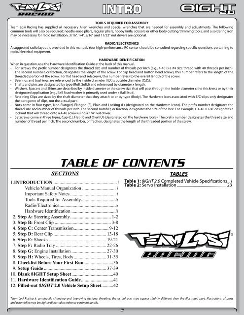
INTROTOOLS REQUIRED FOR ASSEMBLYTeam <strong>Losi</strong> Racing has supplied all necessary Allen wrenches and special wrenches that are needed for assembly and adjustments. The followingcommon tools will also be required: needle-nose pliers, regular pliers, hobby knife, scissors or other body cutting/trimming tools, and a soldering ironmay be necessary for radio installation. 3/16", 1/4", 5/16" and 11/32" nut drivers are optional.RADIO/ELECTRONICSA suggested radio layout is provided in this manual. Your high-performance RC center should be consulted regarding specific questions pertaining toradio/electrical equipment.HARDWARE IDENTIFICATIONWhen in question, use the Hardware Identification Guide at the back of this manual.• For screws, the prefix number designates the thread size and number of threads per inch (e.g., 4-40 is a #4 size thread with 40 threads per inch).The second number, or fraction, designates the length of the screw. For cap head and button head screws, this number refers to the length of thethreaded portion of the screw. For flat head and setscrews, this number refers to the overall length of the screw.• Bearings and bushings are referenced by the inside diameter (I.D.) x outside diameter (O.D.).• Shafts and pins are designated by type (Roll, Solid) and referenced by diameter x length.• Washers, Spacers and Shims are described by inside diameter or the screw size that will pass through the inside diameter x the thickness or by theirdesignated application (e.g., Ball Stud washer is primarily used under a Ball Stud).• Retaining Clips are sized by the shaft diameter that they attach to or by type (Body). The Hardware Icon associated with E/C-clips only designatesthe part genre of clips, not the actual part.• Nuts come in four types, Non-Flanged, Flanged (F), Plain and Locking (L) (designated on the Hardware Icons). The prefix number designates thethread size and number of threads per inch. The second number, or fraction, designates the size of the hex. For example, L 4-40 x 1/4" designates alocknut that will thread onto a 4-40 screw using a 1/4" nut driver.• Setscrews come in three types, Cup (C), Flat (F) and Oval (O) (designated on the hardware Icons). The prefix number designates the thread size andnumber of thread per inch. The second number, or fraction, designates the length of the threaded portion of the screw.TABLE OF CONTENTSSECTIONS1. INTRODUCTION...................................................... iVehicle/<strong>Manual</strong> Organization............................. iImportant Safety Notes....................................... iTools Required for Assembly............................ iiRadio/Electronics.............................................. iiHardware Identification..................................... ii2. Step A: Steering Assembly.................................. 1-23. Step B: Front Clip................................................ 3-84. Step C: Center Transmission............................. 9-125. Step D: Rear Clip............................................. 13-186. Step E: Shocks................................................. 19-217. Step F: Radio Tray........................................... 22-268. Step G: Engine Installation.............................. 27-309. Step H: Wheels, Tires, Body............................ 31-358. Checklist Before Your First Run.........................369. Setup Guide..................................................... 37-3910. Blank 8IGHT Setup Sheet...................................4011. Hardware Identification Guide...........................4112. Filled-out 8IGHT <strong>2.0</strong> Vehicle Setup Sheet..........42TABLESTable 1: 8IGHT <strong>2.0</strong> Completed Vehicle Specifications... iTable 2: Servo Installation................................................... 23Team <strong>Losi</strong> Racing is continually changing and improving designs; therefore, the actual part may appear slightly different than the illustrated part. Illustrations of partsand assemblies may be slightly distorted to enhance pertinent details.ii


