Create successful ePaper yourself
Turn your PDF publications into a flip-book with our unique Google optimized e-Paper software.
1/8-SC ALE 4WD COMP E TITION N ITR O B U G G Y R A C E R O LLE ROWNER’S MANUAL
qSTEP I-01INTROIntro to the 8IGHT <strong>2.0</strong> <strong>Manual</strong>Welcome Team <strong>Losi</strong> Racing 8IGHT <strong>2.0</strong> Owner!Thank you for selecting the 8IGHT <strong>2.0</strong> as your new racing buggy. The 8IGHT <strong>2.0</strong> has already distinguished itself as a top caliber racing chassis and asyou will see, we have made every effort to produce a vehicle that is not only the most competitive but also easy to maintain. The simple step-by-stepassembly sequence and easily followed instructions and drawings combined with Team <strong>Losi</strong> Racing's world famous quality fitting parts will make usingthe 8IGHT <strong>2.0</strong> a most enjoyable vehicle.Please take a moment to read through the following instructions. This will familiarize you with the various parts, assembly tips and descriptions aswell as the tools needed. Taking an extra moment before using your vehicle will help you understand the dynamics of the 8IGHT <strong>2.0</strong> and setup tips toensure the best possible experience.Good luck and good racing,Team <strong>Losi</strong> RacingRegister your <strong>Losi</strong> Product Online:Register your 8IGHT <strong>2.0</strong> now and be the first to find out about the latest options parts, product updates and more. Log on to www.LOSI.com andfollow the product registration link to stay connected.8IGHT <strong>2.0</strong> COMPLETED KIT SPECIFICATIONSOverall Chassis Length: 16.35" (415mm) Wheelbase: 12.71"-12.87" (323-327mm) *Front Track Width: 12.13" (308mm)Overall Length w/Tires: 19.5" (497mm) *Overall Height: 6.625" (168mm) *Rear Track Width: 12.13" (308mm)Note: Final vehicle weight will vary depending on accessories used.*All measurements taken at ride height (32mm).Table 1: 8IGHT <strong>2.0</strong> Completed Vehicle Specifications.Vehicle/<strong>Manual</strong> Organization:The vehicle is composed of different steps marked A through H. Eachstep contains all of the parts necessary to complete a particular sectionof the vehicle. Some of these steps have sub-assembly steps within them.It is helpful to read through the instructions for an entire step prior toworking on your vehicle. Next to each of the step numbers is a check box.At the completion of each step, place a check in this box so that if youmust stop and come back to the assembly, you will be able to pick upwhere you left off.For your convenience, an actual-size Hardware Identification Guide isincluded as a fold-out page at the back of this manual. Hardware thatis not easily differentiable in each step is called out with an icon whichcontains a small picture of the part genre (referenced on the HardwareIdentification Guide), the quantity of that part required for what is shownin the step, and the size or name of that part. To check a part, hold itagainst the silhouette until the correct part is identified. Associated witheach of these parts, in the Hardware Identification Guide, is an LOSA-Number which is used whenordering replacement partsfor your 8IGHT <strong>2.0</strong>. In somecases, extra hardware has beensupplied for parts that may beeasy to lose.Components used in each stepare identified by their relative LOSA-Number and the component’sname. With the exception of a few parts, these are not referenced in theHardware Identification Guide.The molded parts in Team <strong>Losi</strong> Racing vehicles are manufactured todemanding tolerances. When screws are tightened to the point ofbeing snug, the parts are held firmly in place. For this reason, it is veryimportant that screws not be overtightened in any of the plastic parts.In some steps there will be a filled black circle with a white number.These indicate the specific order by which assembly must occur. In caseswhere steps are repeated (front/rear or left/right) these numbers may beomitted. Please note that these numbers will not call out every sub-steprequired for the step’s assembly procedures, they will only highlight thecritical order required for assembly.In each step, there are specific “Detail Icons” (shaped like a stop sign) thatcall out critical precautions or assembly tips for the process. There is areference key that describes the meaning of each of the icons located onthe fold-out Hardware Identification Guide at the back of this manual.To ensure that parts are not lost during construction, it is recommendedthat you work over a towel or mat to prevent parts from rolling away.IMPORTANT SAFETY NOTES:1. Select an area for assembly that is away from the reach of smallchildren. Some parts in this vehicle are small and can be swallowedby children, causing choking and possible internal injury; PLEASE USECAUTION!2. The shock fluid and greases supplied should be kept out ofchildren’s reach. They are not intended for human consumption!3. Exercise care when using any hand tools, sharp instruments, orpower tools during construction.4. Carefully read all manufacturer’s warnings and cautions for anychemicals, glues, or paints that may be used for assembly andoperating purposes.i
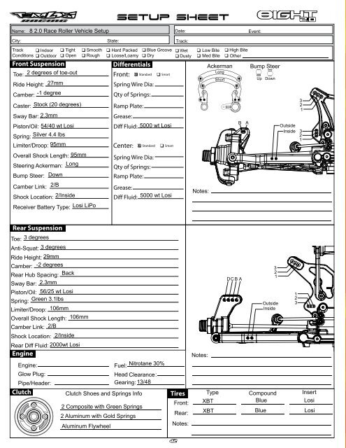
DifferentialsFront: Standard SmartSpring Wire Dia:Qty of Springs:Ramp Plate:Grease:Diff Fluid:Center: Standard SmartSpring Wire Dia:Qty of Springs:Ramp Plate:Grease:Diff Fluid:40
LHARDWARECap Head Flat Head 1 Flat Head 2 Button Head2-56 x 1/4" (A6232)2-56 x 1/2" (A6254)4-40 x 3/8" (A6206)4-40 x 1/2" (A6204)3 x 8mm (A9106)3 x 12mm (A3500)5-40 x 3/8" (A6270)8-32 x 3/8" (A6264)8-32 x 1/2" (A6262)2-56 x 1/4" (A6255)4-40 x 1/4" (A6234)4-40 x 1/2" (A6256)5-40 x 3/8" (A6277)4-40 x 5/8" (A6221)5-40 x 1/2" (A6240)5-40 x 1/2" (A6271)5-40 x 5/8" (A6275)5-40 x 1-7/8" (A6273)5-40 x 1/2" (A6278)5-40 x 20mm (A6281)5-40 x 7/8" w/ 5/8" Shoulder (A4414)5-40 x 3/4" (A6272)600-01575-40 x 3/4" (A6279)5-40 x 7/8" (A6273)5-40 x 1" (A6280)Set Ball Bearings 1 Ball Bearings 28-32 x 3/4" (A6263)F 5-40 x 1/8" (A6228)C 4-40 x 1/8" (A6227)C 5-40 x 3/16" (A6299)5x10x4mm (A6949)5x13x4mm (A6949)PinsC 8-32 x 1/8" (A6298)6x10x3mm (A6946)2.5 x14mm (A3526)F 5-40 x 1/8" (A6297)F 8-32 x 1/8" (A6296)O10-32 x 3/8" (A6295)5-40 x 22mm (A6045)600-01625x11x4mm (A6947)F 5x11x4mm (A6948)8x14x4mm (A6945)1/2” x 3/4" (A6953)2.5 x 12.37mm (A3523)3 x 17mm (A3531)2.5 x 12.8mm (A3505)4 x 66mm (A6500)Washers Shims Retaining ClipsBall Stud (A6215)5x7x.2mm (A9104)5mm E-clip (A6109)3.5 x 53mm (A6503)#4 x .030" (A6350).250 x .094 x .020" (A9166)650-00526x11x.2mm (A3501)14x17x.1mm (A4452)Body Clip (A8200)Nuts (Lock/Plain)#4-40 (Mini) (A6306)650-0053 650-005414x17x.25mm (A4452)650-0053 650-0054#5-40 (A6302)#8-32 (A6311)1DETAIL ICON REFERENCE KEYThese numbers are used to identify the critical order in which assembly must occur. *Note: They will not call out every stage of the assembly process.LOSI-LOKApply <strong>Losi</strong>-Lok®CLEARGREASEApply ClearGreaseGLUEApply CA GlueDegrease withMotor SprayOILFill WithSilicone OilPre-TapPay SpecialAttention CUT Cut/TrimEnsure FreeMovementEnsure FreeRotationEnsure ProperOrientationPush FirmL SideShownLRRAssembleOtherSide the Samex2 Repeat/BuildMultipleScrew PartiallyDO NOTOver Tighten/Snug TightTighten41
INTROTOOLS REQUIRED FOR ASSEMBLYTeam <strong>Losi</strong> Racing has supplied all necessary Allen wrenches and special wrenches that are needed for assembly and adjustments. The followingcommon tools will also be required: needle-nose pliers, regular pliers, hobby knife, scissors or other body cutting/trimming tools, and a soldering ironmay be necessary for radio installation. 3/16", 1/4", 5/16" and 11/32" nut drivers are optional.RADIO/ELECTRONICSA suggested radio layout is provided in this manual. Your high-performance RC center should be consulted regarding specific questions pertaining toradio/electrical equipment.HARDWARE IDENTIFICATIONWhen in question, use the Hardware Identification Guide at the back of this manual.• For screws, the prefix number designates the thread size and number of threads per inch (e.g., 4-40 is a #4 size thread with 40 threads per inch).The second number, or fraction, designates the length of the screw. For cap head and button head screws, this number refers to the length of thethreaded portion of the screw. For flat head and setscrews, this number refers to the overall length of the screw.• Bearings and bushings are referenced by the inside diameter (I.D.) x outside diameter (O.D.).• Shafts and pins are designated by type (Roll, Solid) and referenced by diameter x length.• Washers, Spacers and Shims are described by inside diameter or the screw size that will pass through the inside diameter x the thickness or by theirdesignated application (e.g., Ball Stud washer is primarily used under a Ball Stud).• Retaining Clips are sized by the shaft diameter that they attach to or by type (Body). The Hardware Icon associated with E/C-clips only designatesthe part genre of clips, not the actual part.• Nuts come in four types, Non-Flanged, Flanged (F), Plain and Locking (L) (designated on the Hardware Icons). The prefix number designates thethread size and number of threads per inch. The second number, or fraction, designates the size of the hex. For example, L 4-40 x 1/4" designates alocknut that will thread onto a 4-40 screw using a 1/4" nut driver.• Setscrews come in three types, Cup (C), Flat (F) and Oval (O) (designated on the hardware Icons). The prefix number designates the thread size andnumber of thread per inch. The second number, or fraction, designates the length of the threaded portion of the screw.TABLE OF CONTENTSSECTIONS1. INTRODUCTION...................................................... iVehicle/<strong>Manual</strong> Organization............................. iImportant Safety Notes....................................... iTools Required for Assembly............................ iiRadio/Electronics.............................................. iiHardware Identification..................................... ii2. Step A: Steering Assembly.................................. 1-23. Step B: Front Clip................................................ 3-84. Step C: Center Transmission............................. 9-125. Step D: Rear Clip............................................. 13-186. Step E: Shocks................................................. 19-217. Step F: Radio Tray........................................... 22-268. Step G: Engine Installation.............................. 27-309. Step H: Wheels, Tires, Body............................ 31-358. Checklist Before Your First Run.........................369. Setup Guide..................................................... 37-3910. Blank 8IGHT Setup Sheet...................................4011. Hardware Identification Guide...........................4112. Filled-out 8IGHT <strong>2.0</strong> Vehicle Setup Sheet..........42TABLESTable 1: 8IGHT <strong>2.0</strong> Completed Vehicle Specifications... iTable 2: Servo Installation................................................... 23Team <strong>Losi</strong> Racing is continually changing and improving designs; therefore, the actual part may appear slightly different than the illustrated part. Illustrations of partsand assemblies may be slightly distorted to enhance pertinent details.ii
qSTEP A-01STEP ASteering Link Assembly q STEP A-02Servo Saver AssemblyA9168 A9166Steering Servo ArmSteering Servo Armx 1L 4-40 x 3/16"A6306A4423Servo Saver Tubex 14-40 x 1/2"A6256A6043A6045Rod Rod End Ball Ball EndMaintenance TipA6045 A6043Rod EndRod EndLOSI-LOKx 1x 15-40 x 5/8"A6045x 14-40 x 1/2"A6256A4412Steering DragLinkL 4-40 x 3/16"A6306A4412Drag Link ScrewA4423Steering ArmA4406Steering BellCrank RA4406Steering Bell Crank LA4423Servo Saver Spring2.26"57.40mmA4423Saver NutTighten the Servo Savernut all the way down and thenback it off 2 1/2 turns.qSTEP A-03Fuel Tank/Chassis Brace Assemblyx 24-40 x 1/2"A6204x 2#4 x .030"A6350A9162Fuel Tankx 44-40 x .150"A6249A4413Front ChassisSupportLOSI-LOKx 3L 5-40 x 1/4"A6302A4404ChassisA4408Steering PostA4424Tank Mountx 65-40 x 1/2"A6721LOSI-LOK1
qSTEP A-04Steering/Top Plate AssemblySTEP AA4413Front Chassis Bracex 1LOSI-LOK 5-40 x 1/2"A6271LOSI-LOKA4424Front Body Mountx 25-40 x 1/2"A6278x 15-40 x 3/8"A6270x 46x10x3mmA6946qSTEP A-05Completed Steering Assembly2
STEP BqSTEP B-01Ring Gear AssemblyqSTEP B-03Complete Diff AssemblySolidx 12.5 x 12.80mmA3505A3503Outdrive CupFill with 5000 wt oil just above theplanetary gear1323x12mmA3500x 4x 1F 8x14x4mmA69484A3509Ring GearA3502Sun Gearx 26x11x0.2mmA3501A3505O-ringA3505Diff SealqSTEP B-02Diff Case AssemblyA3502Planetary GearA3502Planetary GearAxleSolidx 12.5 x 12.80mmA35053x 1F 8x14x4mmA6948A3503Outdrive CupTighten the diff screwsin this order113242A3500Diff Housing4x 2A3505O-ringA3502Sun Gear6x11x0.2mmA35013
STEP BqSTEP B-04Front Diff InstallTo prevent fine dust from entering thegearbox, apply a thin bead of greasealong the edge of the case as pictured.x 1F 8-32 x 1/8"A629834LOSI-LOKx 25x11x4mmA6947A3514Drive Adapterx 25-40 x 7/8"A6273621A3508Pinion Gear, BevelA4427Front Diff Casex 25-40 x 1/2"A62405A4427Front Diff CoverqSTEP B-05Front Spindle & CV AssemblyA3535CV Driveshaft1A3523CV CoupleSolidx 12.5 x 12.4mmA35233x 11/2” x 3/4"A6953A1707Left Spindle2x 1A3522Axle48x14x4mmA6945Solidx 163 x 17mmA3531A3530Wheel Hexx 1C 8-32 x 1/8"A629857LOSI-LOK4
qSTEP B-06Spindle/Carrier AssemblySTEP Bx 1O 10-32 x 3/8"A6295A1709Left Spindle CarrierA1703Left Front Arm5x 28/32 x 3/4"A62632A6501Hinge Pin4 4A1701Front Arm Bushing51x 2C 5-40 x 3/16"A6299332qSTEP B-07Front Suspension Arms AssemblyA4431Front Inner HingePin CapA1744Front Inner HingePin BraceSolidx 24 x 65mmA6500x 45-40 x 3/4"A6272A4431Front Outer HingePin CapA1744Front Outer HingePin Brace5
qSTEP B-08Sway Bar AssemblySTEP BInstall the Sway Bar Ball onto the Sway Bar Wire until theend of the wire is flush with the ball as pictured above.A1750Sway Bar LinkA1750Sway Bar BallA1750Sway Bar MountCapx 24-40 x 5/8"A6221x 2C 4-40 x 1/8"A6227x 42-56 x 1/4"A6232A1750Sway Bar, 2.3mmA1750Sway Bar Ballx 2C 5-40 x 1/8"A6228qSTEP B-09Tie Rod/Shock Tower AssemblyA1714Front Shock TowerA5438Shock Standoffx 2L 8-32 x 11/32"A6311A60556.8mm FlangedSuspension Ballx 2L 5-40 x 1/4"A6320Be sure to install the assembled TieRod onto the car with the groove(next to the center square section)on the driver’s left side for easieradjustment later.A65424mm Turnbuckle, FrontA6046Rod EndA4453Shock TowerMount Capx 45-40 x 1/2"A6278A60566.8mm Suspension BallA6057Camber Standoffx 25-40 x 3/4"A62795-40 x 1"A6280x 13.71"94.256
qSTEP B-10Center CV AssemblySTEP BSolidx 12.5mm x 14mmA3253A3526CV Coupling, Center12LOSI-LOKA3526Driveshaft, FrontCenterx 1F 5-40 x 1/8"A6228qSTEP B-11Steering Rod AssemblyA3537Grease BootA6050Steering BallBe sure to install the assembled TieRod onto the car with the groove(next to the center square section)on the driver’s left side for easieradjustment later.A6046Steering Rod EndA6542Steering Turnbucklex 15-40 x 5/8"A62753A6050Steering BallA6046Steering Rod EndA6542SteeringTurnbuckleA6050Steering Ballx 15-40 x 1/4"A63023.62"9<strong>2.0</strong>0mm7
qSTEP B-12Front Clip AssemblySTEP Bx 25-40 x 3/4"A6279x 25-40 x 3/4"A627241A4453Front Bulkhead Spacer23x 48-32 x 1/2"A6262A4422Front BumperqSTEP B-13Completed Front Assembly8
STEP CqSTEP C-01Ring Gear AssemblyqSTEP C-03Complete Diff AssemblySolidx 12.5 x 12.80mmA35053Fill with 5000 wtoil just above theplanetary gear.1A3502Sun Gear3x12mmA3500x 424A3506Center Outdrivex 2x 1F 8x14x4mmA69486x11x0.2mmA3501A3505O-ringA351648T Spur GearA3505Diff SealA3502Planetary GearAxleqSTEP C-02Diff Case AssemblySolidx 1A3502Planetary Gear2.5 x 12.80mmA35053x 2AA3500Diff HousingA3502Sun Gear6x11x0.2mmA3501A3506Center Outdrive4A3505O-ring21Tighten the diff screwsin this order.x 1F 8x14x4mmA694831429
qSTEP C-04(.5mm)(.020”)Center Top Brace Assemblyx 15mm E-clipA6109LOSI-LOKSTEP Cx 2F 5-40 x 1/8"A6297qSTEP C-05A9168Rear Brake RodLinkage AssemblyA9168Front Brake ActuatorLOSI-LOKA9168Throttle Rod Endx 12-56 x 1/2"A6254A4420Top Center Bracex 12-56 x 1/4"A6232x 2.250x.094x020"A9168A3544BrakeCam BushingA9168Throttle Return SpringA9168Rear BrakeActuator211A3544Front Brake CamA9166Brake WireA9168Threaded Servo RodA9168Throttle Servo ArmA9168Throttle Actuatorx 3C 4-40 x 1/8"A6227A9168Adjuster Collar(7mm)(.2760”)2A3544Rear Brake CamA9168Brake Lever CollarqSTEP C-06Linkage AssemblyqSTEP C-07Air Filter Mount & Guardx 2LOSI-LOKC 4-40 x 1/8"A6227A9168Brake Lever CollarA9168Brake Bushing(9mm)(.3545")Cut two piecesof fuel tubingto picturedsize.A4422Air Filter GuardA9150Air Filter Mountx 55-40 x 3/8"A6277x 2.250x.094x.020"A9168A9135Fuel LineAssemble both Front andRear Brake Lever Collars2.80mm (.11") from the endof the Brake Rod.A4422Tank Guard10
qSTEP C-08Brake Caliper AssemblySTEP CA3546Front Brake PadA3546Rear Brake Pad.307".307”7.80mm7.80mmA4420Center Diff MountA3546Brake Shoulder ScrewA4420Rear CenterDiff MountqSTEP C-09Center Diff/Brake Rotor Assembly4x 45-40 x 3/8"A627732A3545Front Brake Disk31A3545Rear Brake Disk111
qSTEP C-10Center Diff InstallationSTEP CCaution! Ensure thatthe driveshaft is insertedinto the slot of the centeroutdrive while installing theCenter Diff assembly.x 48-32 x 1/2"A6262qSTEP C-11Completed Center Diff Assembly12
qSTEP D-04Rear Diff InstallationSTEP DA4414Rear Chassis Supportx 1F 8-32 x 1/8"A6296x 15-40 x 7/8"A4414A3514Drive AdapterLOSI-LOK4A4451Bearing Insert, LR5x 214x17x0.25mmA4452x 114x17x0.10mmA44523x 21x 15x11x4mmA69472L 5-40 x 1/4"A6302x 25-40 x 7/8"A6273A4450Rear BulkheadA4450Rear Bulkhead Cover76x 314x17x0.10mmA44525A3508Pinion GearA4451Bearing Insert, RRThe 8 <strong>2.0</strong> comes with (2) .25mm shims and(1) .10mm shims on the left bearing insert.On the right bearing insert there are (3).10mm shims. We advise that you start withthis gear mesh with your new vehicle.qSTEP D-05Rear Hub & CV AssemblyA3523CV CouplingA3535Driveshaft1Solidx 12.5 x 12.4mmA3523A1730Left Rear Hub2 3x 1A3522Axle48x14x4mmA6945Solidx 13 x 17mmA3531x 11/2” x 3/4"A69536x 1C 8-32 x 1/8"A6296A3530Wheel Hex57LOSI-LOK14
qSTEP D-06STEP DRear Suspension Arm AssemblyA17493 toe/3 Anti-Squat Pivot Bracex 25-40 x 1-7/8"A6273A4431Rear Outer PivotBrace Capx25/40 x 3/4"A6272x 2O 10-32 x 3/8"A6295Solidx 24 x 66mmA6500A1725Left Rear ArmA4431Rear Inner PivotBrace CapA1745Rear Pivot Bracex 1A65033.5mm Hinge PinL 5-40 x 1/4"A6302A4453Hub Spacer .050”qSTEP D-07Sway Bar AssemblyA1750Sway Bar LinkA1750Sway Bar Bar, ArmA1750Rear Sway Bar, 2.3mmx 24-40 x 5/8"A6221x 25-40 x 1/8"A6297A1750Sway Bar Ballx 42-56 x 1/4"A6232A4453Sway Bar Mount Capx 2C 4-40 x 1/8"A6227Install the Sway Bar Ball onto the Sway Bar Wire until theend of the wire is flush with the ball as pictured above.15
qSTEP D-08Wing Mount AssemblySTEP DA4435Wing Mount BraceA4435Right Wing Mountx 2L 5-40 x 1/4"A6302x 45-40 x 3/4"A6279A4435Left Wing Mountx 35-40 x 1/2"A6278A4424Rear Body Mountx 2L 8-32 x 11/32"A5438Shock Stand-OffA1735Rear Shock TowerqSTEP D-09Rear Shock Tower Installationx 25-40 x 3/4"A6279x 25-40 x 1/2"A627816
qSTEP D-10Tie Rod InstallationSTEP DA60556.8mm Suspension Ball, FlangedA65444mm RearTurnbucklex 15-40 x 3/4"A6279A6542Rod EndA60566.8mmSuspension Ballx 2L 5-40 x 1/4"A6302x 25-40 x 1/4"A63023.79"96.255-40 x 1"A6280x 1qSTEP D-11Center CV AssemblySolidx 12.5mm x 14mmA3526x 1F 5-40 x 1/8"A6297A3536CV Coupling, Center421LOSI-LOKA3536Driveshaft, Center Rear3A3537Grease Boot17
qSTEP D-12Rear Clip AssemblySTEP Dx 2L 5-40 x 1/4"A6302Caution! Ensure that the driveshaftis inserted into the slot of thecenter outdrive while installing theRear Clip assembly.x 25-40 x 1/2"A6240x 48-32 x 1/2"A6262qSTEP D-13Completed Rear Assembly18
qSTEP E-01Shock AssemblySTEP E• Clean the 2-56 x 1/4" Button Head Screw and apply <strong>Losi</strong>-Lok to the threads.• Install the #54 Shock Piston on the front shock shaft and a #56 Shock Piston on the rear shock shaft using the 2-56 x 1/4" Button Screw into theShock Shaft with a .050" Allen Wrench.• Place a drop of Shock Oil into the bottom of the Shock Body to lubricate the Shock Seals.• Thread the Shock Shaft into the Shock End using pliers. Used caution when threading the Shock Ends onto the Shafts. Avoid gouging orscratching the Shock Shaft while gripping the Shock Shaft with pliers by placing the edge of a towel over the shaft, then gripping the portion ofthe shaft covered by the towel. This method will work very well to protect the Shock Shafts from damage.• Ensure the Shaft is fully extended when filling the shock.• Fill the Front Shock Body with 40 wt Shock Oil and the Rear Shock Body with 25 wt until the oil is to the top of the body.• “Work” the Shock Shaft up and down 8 times. This will release the air bubbles trapped beneath the piston. Place the filled shock, in the uprightposition, off to the side for a few minutes until the air bubbles escape from the oil.• Once all the air bubbles are out of the oil, gently place the Shock Bladder onto the shock as shown. Some oil should “bleed” from the shock.• Screw the Shock Cap onto the Body until some resistance is felt.• Slowly push the Shock Shaft up. This will bleed excess oil from the shock.• Tighten the cap all the way down using the shock tools included in your vehicle.• Move the Shock Shaft up and down. The shaft should be easy to push up into the body of the shock. If increased pressure is felt towards the top,there is too much oil in the shock. Loosen the Shock Cap and “bleed” the shock as done previously.• Make sure each pair (front/rear) Shocks have the same rebound and compression. This is checked by holding one shock in each hand horizontallyand pushing them together by the Shock End. Watch carefully to ensure that both compress evenly. Now release both shocks and again watchcarefully as they should rebound the same.• Install the Shock Adjustment Nut O-ring into the Shock Adjustment Nut before installing the Nut onto the Shock Body.x 12-56 x 1/4"x2Frontx2RearA5440Shock PistonLOSI-LOKA5420Shock CapA5421Shock Cap BottomA5440O-ring Shield#56Shock Piston forthe Rear Shocks#54Shock Piston forthe Front ShocksA5429Shock Shaft O-ringA5440Shock Shaft BushingA5429Shock Shaft O-ringA5411Front Shock ShaftA5413Rear Shock ShaftA5430Shock BladderA5429Shock Bottom CapO-ringA5401Front Shock BodyA5403Rear Shock BodyA5435Shock End BallA5435Shock EndA5424Shock Adjuster NutO-ringA5424Shock Adjuster Nut19
qSTEP E-02STEP EShock Boot & Spring Assemblyx2Frontx2RearA5426Shock BootA5451Silver Front SpringA5458Green Rear SpringA5435Spring CupqSTEP E-03Front Shock InstallationA5435Shock Mount Bushingx 2L 5-40 x 1/4"A6302x 25-40 x 20mmA6281x 1C 4-40 x 1/8"A622720
qSTEP E-04Rear Shock InstallationSTEP EA5435Shock Mount Bushingx 2L 5-40 x 1/4"A6302x 1C 4-40 x 1/8"A6227x 25-40 x 20mmA6281qSTEP E-05Completed Shock Assembly21
qSTEP F-01Chassis Guard InstallationSTEP FA4432Chassis Guardsx 55-40 x 3/8"A6270qSTEP F-02Switch InstallationOptional Blank Switch Mount PlateIf not using a switch, install the optionalBlank Switch Mount Plate in place of theSwitch Plate.x 34-40 x 3/8"A6206Supplied withswitch(not included)A4421Switch MountA4421A4418Blank Blank SwitchPlateA4421Switch CoverA4421Radio Tray22
qSTEP F-03Servo Chart/Wiring DiagramSTEP FSanwaJRAirtronicsServo Manufacturer, Make/ModelServoSpacerServoHornAll (DZ9100T/S Needs Spacer) No 23T94357Z, 94358Z, 94649Z, 94360Z,94452Z, 94758Z, 94737Z, 94738ZYes94102Z, 94112Z Yes23TSteeringServo WiresHitecFutabaAll No 24TAll (S9102 DOES NOT FIT) No 25TSwitchWiresThrottleServoWiresPropoKONoPDS-2123, 2344, 2363, 2365, 2366NoTable2: Servo assembly and installation23TAirtronics® is a registered mark of Sanwa Electronic Instrument Co., Ltd., Osaka, Japan.Futaba is a registered trademark of Futaba Denshi Kogyo Kabushiki Kaisha Corporation of JapanKO PROPO® is a registered trademark of Kondo Kagaku Co., Ltd., Tokyo, Japan.qSTEP F-04Throttle Servo InstallationA9168Horn Insertx 44-40 x 1/2"A6204x 4#4 x .030"A6350See Table #2A4453Servo SpacerA4421Servo Mounting Backplate23
qSTEP F-05Steering Servo InstallationSTEP FA9168Horn Insertx 44-40 x 1/2"A6204x 4#4 x .030"A6350A4453Servo SpacerSee Table #2A4421Servo Mounting BackplateqSTEP F-06Receiver/Antenna Tube AssemblyA4003Antenna Antenna CapCapA8313<strong>Losi</strong> A8313 NameplateTL Name PlateA4002Antenna Antenna TubeTubeA4421Receiver A4418 CoverReceiver Cover12x 1Body ClipA8200x 1F 5-40 x 3/16"A629924
qSTEP F-07Receiver Battery DoorSTEP FOptional Battery CoversHigh Profile Cover should be used withHump pack type receiver packs.Low Profile Cover should be used withLiPo type receiver packs.x 24-40 x 1/2"A6256A4421Battery Cover,High ProfileA4421Battery Cover,Low Profilex 2Body ClipA8200A4421Battery Foam PadqSTEP F-08Radio Tray Installationx 48-32 x 3/8"A626425
qSTEP F-09Servo Horn InstallationSTEP FSupplied withservo(Not Included)Ensure the servo gear is centered before attachingthe Servo Horns. This is best accomplished byconnecting the servos to the radio system andsetting the trim to center.qSTEP F-10Completed Radio Tray Installation26
qSTEP G-01Clutch AssemblySTEP GA9107Composite Clutch ShoeA9113Clutch Spring GreenLOSI-LOKCompositeShoeAluminumShoeA9105Aluminum Flywheel1A9105Flywheel ColletA9114Clutch Spring GoldA9106Clutch Pins2A9103Clutch NutA9108Aluminum Clutch ShoeqSTEP G-02Clutch Bell AssemblyUse the appropriate numberof shims to achieve properclutchbell end play. Generally.25mm to.50mm isoptimum.x 25x7x0.2mmA9106x 15x13x4mmA6949A9106Clutch Spacerx 15x7x0.2mmA91063 x 8mmA9106x 1x 15x10x4mmA6949A9116Clutch Bell 13TLOSI-LOK27
qSTEP G-03Engine Mount AssemblySTEP Gx 45-40 x 1/2"A6240LOSI-LOKBall StudA6215x 4Pipe/Header(Not supplied)A9154Right EngineMountA9154Left EngineMountqSTEP G-04Air Filter AssemblyTech TipWith a clean rag or paper towel takethe air filter and squeeze it betweenthe rag to remove any excess airfilter oil. The goal is to remove allthe oil blotches from the filter toimprove engine performance.12A9150Air Filter BodyA9150Air Filter Bootx 14-40 x 3/8"A6206A9151Secondary Air FilterA9151Primary Air FilterA9150Air Filter End Cap28
qSTEP G-05Air Filter InstallationSTEP G12qSTEP G-06Pipe Mount AssemblyLOSI-LOKx 18-32 x 1/8"A6298A9165Pipe WireTrim pipe mount in smallincrements as needed tomount pipe. Ensure thatthe wire clears all steeringcomponents.A9165Pipe Wire MountLOSI-LOKx 18-32 x 3/8"A626429
qSTEP G-07Engine InstallationSTEP G• Adjust the gear mesh between the Clutch Bell and the Spur gear bysliding the engine mounts in the slots of the chassis. In order to functionproperly, the Gears should be as close as possilbe, but still have a smallamount of backlash (space between the Gear teeth).• Place a piece of paper between the Clutch Bell gear and Spur gear, slidethe engine sideways until the paper is pinched between the gears andtighten the engine mount screws. This will give a small amount of spacebetween the gears.• You should be able to rock one gear back and forth slightly whileholding the other one steady. Be sure to check the gear mesh all the wayaround the spur gear.• Once the engine alignment and gear mesh are correct, tighten all of thescrews. Re-check the gear mesh after all the screws are tight to ensurethe engine mounts did not move.x 1Body ClipA8200Supplied withpipe(not included)21LOSI-LOKx 48-32 x 1/2"A6262x 4#8 CountersinkA6351LOSI-LOKqSTEP G-08Fuel Tube/Completed Engine AssemblyA9315Fuel LineA9316Fuel Line Clip30
qSTEP H-01Tire MountingSTEP H12A7763BXBT , Blue1/8 Buggy FoamInsert. Only soldwith Tires.A77511/8 Buggy Wheel,YellowqSTEP H-02Tire Gluing••The tires are already glued to the wheels. Here are the steps to show you how to complete this process. This can be done by using a fast-curing super glue orcyanoacrylate glue (LOSA7880, LOSA7881), available at your local hobby shop. Install a tire gluing rubber band around the outside of the tire, in line with the beadto hold it onto the wheel. <strong>Losi</strong> offers a complete tire gluing kit which includes glue and tire gluing rubber bands (LOSA7884).Now slightly pull back the tire bead from the wheel and apply a thin bead of glue between the tire bead and the wheel all the way around, wait for this side to dryand do the same to the other side until the tire is firmly adhered to the wheel. Allow the glue to dry thoroughly before continuing.31
STEP HqSTEP H-03Tire InstallationLOSI-LOKA3531Wheel HexesLOSI-LOKqSTEP H-04Wing Installation1A8130Wing Buttonx 2Body ClipA82002A8130Rear Wing32
qSTEP H-05Body Painting & TrimmingSTEP HPainting:Prepare the Lexan Body for painting by washing it thoroughly (inside and out) with warm water and liquid detergent. Dry the body with a clean,soft cloth. Use the supplied window masks to cover the windows from the inside. A high-quality masking tape should be used on the inside of thebody to mask off any stripes, panels, or designs that you wish to paint on the body. Use acrylic lacquer or other paints recommended for Lexan(polycarbonate). (NOTE: LEXAN RC CAR BODIES ARE MEANT TO BE PAINTED FROM THE INSIDE!) Apply paint to the inside of the Body. Remove themasking tape for the next color and continue. Try to use darker colors first. If you use a dark color after a light color, apply a coat of white paint overthe lighter color before applying the darker color, or if you are painting over white, coat it with silver. This will help prevent the darker color frombleeding through the lighter color.Mounting:The body is already cut out for mounting. However you will need to cut out the area for the pipe stinger. This should be done before you paint yourbody so you can easily see where it exactly needs trimmed.Stickers:After the body is mounted, REMOVE THE PROTECTIVE FILM ON THE OUTER SURFACE, now you can apply the stickers.A80958IGHT <strong>2.0</strong> BodyRemoveprotective filmafter painting33
qSTEP H-06Body MountingSTEP HA8095Body Spacerx 2Body ClipA820034
q STEP H-07Completed Chassis AssemblySTEP H35
CHECKLISTBEFORE RUNNING YOUR NEW 8IGHT <strong>2.0</strong> OFF-ROAD RACING BUGGY for the first time, you should run down the following checklist in order andcomplete the listed tasks. We’re sure you’re anxious to get out and run your new 8IGHT <strong>2.0</strong> now that it’s built, but please note that fine-tuning of theinitial setup is an essential part of building a high-performance racing buggy such as your new 8IGHT <strong>2.0</strong>. Following this simple Checklist and the TeamTips will help to make the first run with your new car much more enjoyable.1. Breaking in the differential:While holding the chassis with only the left side tires firmly on theground, give the car about one eighth throttle, for 30 seconds. Theright side tires should spin freely during this time. Repeat this withonly the right side tires held firmly to the ground, allowing the lefttires to spin. Repeat these steps at least two more times.2. Check for free suspension movement:All suspension arms and steering components should move freely.Any binds will cause the car to handle poorly.3. Set the ride height:Set the ride height on your buggy so that the bottom of the chassisis 27mm from the ground in front and 29mm in the rear by adjustingthe shock adjustment nuts, effectively increasing or decreasing preloadon the springs. See the Setup Guide for additional informationon ride height adjustment.4. Set the camber:Adjusting the camber tie rod length changes the amount of camber.Use the <strong>Losi</strong> wrench to adjust the tie rods once installed. Rotatingthe tie rods towards the front end of the vehicle will shorten thelength, increasing negative camber. Rotating the tie rods towardsthe back of the car will lengthen them, increasing negative camber.Set the front tires to have 1 degree of negative camber and ensurethat they are adjusted equally, left to right. Set the rear tires to have2 degrees of negative camber and ensure that they are adjustedequally, left to right.5. Set the front toe-in:Adjust the front steering tie rods so that when the servo is centeredon the transmitter, the front tires are both pointing slightly out with2 degrees of toe-out. Refer to the Setup Guide for more informationon toe-in/out.6. Charge a receiver battery pack:Charge a battery pack as per the battery manufacturer’s and/orcharger manufacturer’s instructions so that radio adjustments canbe made.7. Set the transmitter steering trim:The steering trim tab on the transmitter should be adjusted sothat the car rolls straight when you are not touching the steeringwheel/stick. If the servo and steering link were installed correctly,the wheels should turn equally to the left and right. If this is not thecase, refer to Table 2 and ensure that the steering servo and hornwere properly installed. Also check the steering link length as notedin Step A-01. Make sure the throttle trim is set so that the brakes arenot “dragging” in the neutral position.8. Set the transmitter throttle and brake trim:The throttle trim tab on the transmitter should be adjusted so thatthe brakes are not dragging in the neutral position. The idle adjustmentscrew on the carburetor should be set at approximately 1mmopen. When the throttle trigger is pulled back to the maximum, thecarburetor is fully opened.36
SETUP GUIDETIPS AND HINTS FROM THE TEAMBefore you start making changes on your 8IGHT <strong>2.0</strong> Off-Road Racing buggy, you need to make a few decisions. First of all, tires, and how they are setup, have a tremendous impact on overall performance. Before you start making changes on the chassis setup, take a moment to observe a few of thefastest cars at the track and what type of tire and inner liner they are running. You will find the best adjustment will become a personal decision basedon the “feel” that each of these adjustments yield. Never make more than one change at a time; if the change you made works adversely, or doesn’taddress your need, return to the previous position and try something else. Team <strong>Losi</strong> Racing development team has put hundreds of hours on the8IGHT <strong>2.0</strong> to arrive at the setup we put in the instruction manual. If you find that you have lost the “handle” go back to the vehicle (stock) setup, as thissetup has proven to be reliable, consistent and easy to drive.All of us at <strong>Losi</strong> are sure that you will find the 8IGHT <strong>2.0</strong> Off-Road Racing Buggy to be the most versatile and easiest car to drive fast, with greatconsistency. We hope the information in the following guide helps you to enjoy your 8IGHT <strong>2.0</strong>, and racing it, as much as we do. For the latest in setupand accessory parts information, visit the <strong>Losi</strong> web site at: www.losi.com regularly. Please check the <strong>Losi</strong> web site periodically to find out new setupinformation as we are always testing on all types of tracks and surfaces. Also note that there are many ways to set up a car. The rules we follow canreverse sometimes with different driving styles or different setup styles, so test for yourself and you will find a set up that works right for you.Tuning the Engine:Should be done following the manufacturer's instructions. Turning the needle valve clockwise, the fuel mixture will become leaner – meaning thatthe engine will draw less fuel. When the needle valve is turned counterclockwise, the fuel mixture becomes richer, meaning that, the engine will drawmore fuel. The high speed needle affects the fuel mixture at fuel throttle while the low speed needle only affects the fuel mixture at idle and the lowend of the throttle band. Our recommended engine and pipe combo for your Team <strong>Losi</strong> Racing 8IGHT <strong>2.0</strong> is the GRP Mario Rossi tuned .21 engine andGRP 2053 Pipe.To Shut Off the Engine:Simply use the included pipe plug or simply bump the flywheel with a wrench or plastic handled tool. <strong>Losi</strong> also makes a tuning driver with a built-inplug for the pipe (LOSA99167).The Receiver Battery:The receiver battery is an important, frequently overlooked part of gas-powered vehicles. A low receiver battery can cause the vehicle to have amind of its own. The result can be runaway vehicle or a poorly responding radio system. The length of time that a receiver battery pack’s charge lastsdepends on the type of servos that are used. If you will be using a NiCd or NiMH receiver pack, it is recommended that a minimum battery size of1100mAh and minimum voltage of 5.4 volts be used. Recommended batteries that are offered by <strong>Losi</strong> are LOSB9950 6V 1100mAh NiMH ReceiverPack or LOSB9820 7.4V 2000mAh 2C LiPo Receiver Pack. Please note that a voltage regulator will be needed if you choose to use a Lithium Polymer(LiPo) receiver pack. <strong>Losi</strong> offers voltage regulators with a switch, LOSB9608 and without a switch, LOSB9609.Droop:Always measure the droop of the 8IGHT <strong>2.0</strong> with the shocks on the buggy. Droop is always measured from the center of the top shock mount to thecenter of the bottom shock screw. More droop (travel) in the front will have more on-power steering and allow the buggy to roll more on the rearwhen on throttle. More droop (travel) in the rear will increase off-power steering and allow the buggy to roll on the front when off throttle. More frontand rear droop will accelerate better in bumps when going straight, but can cause the buggy to traction roll in rough turns. Less front and rear droopwill slide over bumps better in turns and may be better on high-speed and high-traction tracks.Front Camber Links:The lower camber link locations on the tower have more camber gain (total camber change through the suspension travel). Running the cambertie rod in the lower holes will increase off-power steering and make the vehicle more aggressive; however you may lose some consistency. Morecamber gain is good on small tight tracks. We have found that running less camber gain in the front suits the car the best for consistency and steeringbalance. On the 8IGHT <strong>2.0</strong> we offer a longer camber link on the spindle carrier. A longer front camber link will make the vehicle feel stiffer and this willkeep the buggy flatter with less roll and increase high-speed steering. A short front camber link will roll more and make the vehicle more aggressive.Too short of a front link may make the vehicle feel twitchy.Rear Camber Links:The 8IGHT <strong>2.0</strong> now has only three camber locations on the rear tower, however, we have added another inside hole on the rear hub. The stockcamber link setup for the 8IGHT <strong>2.0</strong> is location #2 on the tower and B in the hub. By using a longer rear camber link you will have less roll andimprove stability and traction. A shorter rear camber link will have more roll and increase steering and better handling in the bumps. Running “A” inthe rear hub will generate more corner rotation entering the turn, but decrease steering on exit. Running “B” in the hub will be more stable enteringthe turn and increase steering on exit.Pistons:Generally smaller hole pistons, #56, have stiffer damping, slower weight transfer, slower response, and will land large jumps better. Larger holepistons, #54, have softer damping, increased traction, quicker weight transfer/response, and bottom out easier off large jumps.Shock Oil:Lighter shock oil has more overall traction and responds quicker. Thicker oil has less overall traction and reacts slower. On high bite/smooth tracks,thicker oil is easier to drive. Make sure you adjust oil when there is a drastic temperature change (20-25 degrees). If it gets cold outside you need to goto lighter shock oil. If it gets hotter outside you need to go to thicker weight shock oil.Front Toe:You never want to run toe-in on the front of the 8IGHT <strong>2.0</strong>. Front toe-in (longer steering rods) decreases steering response entering and in the middleof the turn but will increase on power steering. Toe-out (shorter steering rods) increases steering response when entering the turn and increasesstraight line stability, however, it will decrease on power steering.37
SETUP GUIDERear Toe-in:The 8IGHT <strong>2.0</strong> is equipped with 3 degrees of toe-in per side. Less rear toe-in will increase the wheel base of the buggy and decrease forwardtraction, but will increase top speed and side traction in the middle of a turn. More toe-in will increase forward traction, have more off-powersteering and less side traction.Wheel Base:The 8IGHT <strong>2.0</strong> is equipped with a long wheelbase. A shorter wheelbase (spacers behind the rear hubs) increases on-power traction, rear weighttransfer, and has more off-power steering. A shorter wheelbase is better on tight or slick tracks. A longer wheelbase (spacers in front of the rearhubs) decreases off-power steering, is more stable, better in bumps, and has more on-power steering.Sway Bars:The 8IGHT <strong>2.0</strong> is equipped with 2.3mm sway bars on the front and rear. A thinner front sway bar increases front off-power traction, but has lesson-power steering. A thicker front sway bar decreases front off-power traction making the steering smoother entering the turn, but has more onpowersteering. A thinner rear sway bar increases rear traction and decreases on-power steering. A thicker rear sway bar increases stability in themiddle of the turn and increases on-power steering. Thicker sway bars are more stable on high-speed, high-traction tracks.Clutch:On new clutch bells make sure to clean the inside of the clutch bell with scouring pad or fine sand paper to improve the break-in period. Softersprings engage at a lower rpm and have a smoother power band. If the engine doesn’t have enough low-end power try running more preload(spring with more angle) or a stiffer spring. Stiffer springs engage at a higher rpm and hit much harder. If the springs are too stiff it will cause theclutch to slip.Plastic vs. Aluminum Clutch Shoes:We have found the two plastic and two aluminum clutch setup to work best on most tracks, but if the track is very loose, rough, and doesn’t havejumps that are difficult to get over, four plastic shoes will allow more slip and smoother acceleration. Running all four aluminum clutch shoes willhave the most punch, but isn’t as good on slick, rough tracks. Our recommended clutch setup is two aluminum shoes with gold springs and twoplastic shoes with green springs. Whenever you need to rebuild your clutch we recommend the following tips. First of all, be sure to clean all partswith <strong>Losi</strong> Nitrotec Spray Cleaner (LOSA99217) to ensure there is no oil or debris on any of the parts. Cleaning will include all clutch parts includingthe clutch bearings. We like to spray out the clutch bearings to ensure that there is no grease slung from the bearing at high rpm which wouldcause premature clutch wear or slippage. When reinstalling the clutch pins we recommend NOT using any type of <strong>Losi</strong>-Lok on the clutch pins. Byusing <strong>Losi</strong>-Lok on this part, it only makes it difficult to remove the pins. Once the new shoes are installed, pull back each clutch shoe 1mm to makesure they spring back to position to ensure proper movement. You will also want to make sure the clutch bell has anywhere from .25mm to .50mmof movement and spins freely on the crank shaft. You can use <strong>Losi</strong>’s Metric Shim Set, LOSA6356 to dial this in properly. Now that your clutch is fullyrebuilt it is time to break it in. This is done by starting your buggy and having it idle on the ground. While firmly holding the vehicle down, apply ½throttle for three seconds. Repeat this three times to fully seat in your new clutch.Here is a layout of clutch setups ranging from softest to hardest in accelerationClutchSetupNumberShoe/SpringDescription14 Plastic with Black2 Aluminum with Black2 Plastic with BlackUltimately the smoothest and easiest to drive setupClutch Engagement Softest to Hardest2345674 Plastic with Green2 Aluminum with Green2 Plastic with Black4 Plastic with Gold2 Aluminum with Gold2 Plastic with Green2 Aluminum with Gold2 Aluminum with GoldUsed on very loose tracks where little punch is neededUsed on loose high-speed tracks where there are no jumps out of turnsVery smooth, yet has good punch. Motor must have adequate power to pull this clutch setupVery forgiving and reduces wheel spin with punch being sacrificed slightly.Can be used with motors that have great bottom endGood all around setup. Best compromise for punch and mileageIncreased punch with slightly less mileage84 Aluminum with GoldIncreased punch, good for jumps right out of turn, with average mileage.94 Aluminum with 2 Silver and 2 GoldVery aggressive with great punch, engine will run hotter and shoe life will diminish104 Aluminum with SilverMost aggressive, maximum punch. Use with motor that has very low bottom endDifferentials:The 8IGHT <strong>2.0</strong> comes equipped with 5000 wt in the front and center diff, and 2000 wt in the rear diff. Thinner front differential oil increases offpowersteering, but if the oil is too thin the steering will become grabby and inconsistent. Thicker front differential oil increases off-power stabilityand increases on-power steering. Thinner center differential has less forward drive, can unload more under acceleration and is easier to drive onrough and slick tracks. Thicker center differential has more acceleration, increases on-power steering, and less off-power steering. Thicker centerdifferential is better on high bite/smooth tracks. Thinner rear differential has more corning traction and increases steering in the middle of the turn.Thicker rear differential has less steering in the middle of the turn and more forward traction.38
SETUP GUIDEShock Mounting Positions:More inclined (moving the shocks in on the tower) has softer initial damping and is more forgiving. Less inclined (moving the shocks out on thetower) makes the car more responsive and is better for technical tracks.Ackerman:A long Ackerman plate will have smooth off-power steering and is more forgiving. The long Ackerman plate will have more steering on-power. A shortAckerman plate responds quicker and has more steering in the middle of the turn. A short Ackerman plate is better suited for tight technical tracks.Camber:More negative camber in the front has more steering and is more responsive.Less negative camber in the front will have less steering and will be smoother.More negative camber in the rear will have less rear traction, but will increase on-power steering and will be less grabby in bumps. Less negativecamber in the rear will have more rear traction and make the rear of the buggy stay flatter, but if traction is lost it will be more violent. To ensure your8IGHT <strong>2.0</strong> has the correct camber we recommend using our <strong>Losi</strong> Camber Gauge (LOSA99172).Fuel Tank:Your 8IGHT <strong>2.0</strong> comes preinstalled with a fuel tank insert to meet ROAR and RC Pro Series 125cc fuel tank rules. If you are not racing your 8IGHT <strong>2.0</strong>where these rules apply, you can remove the insert to allow for an additional 5cc of fuel and longer run time. Also included in your 8IGHT <strong>2.0</strong> is anEFRA Fuel Kit. This should be used at all EFRA races to ensure your fuel tank volume will not change during racing. The EFRA Fuel Kit ensures that thefuel line and clunk does not come out of the tank, increasing fuel volume. Below is a diagram on how to install the EFRA Fuel Kit.Gearing:The stock gearing for the 8IGHT <strong>2.0</strong> is 13/48. If you are running on a large sweeping track and need more top speed, a 14-tooth clutch bell (LOSA9117)is recommended.Brake Setup:The standard brake bias for the 8IGHT <strong>2.0</strong> is 60% rear - 40% front. If you need the buggy to rotate more under braking, adjust the linkage for less frontbrake. If the buggy is loose entering turns under braking, adjust the linkage for less rear brake or more front brake.Outdrives and Traction:When your 8IGHT <strong>2.0</strong> is new it will have a lot of chassis roll and be a little loose on throttle due to lack of friction in the out drives and crossbones.After about 45-60 minutes of running, the 8IGHT <strong>2.0</strong> will gain traction and stability. Once your 8IGHT <strong>2.0</strong> is broken in, replacing the out drives andcrossbones with new parts will have more corner speed.Bump steer:Running the bump steer ball down you will have smoother steering in the middle of the turn. With the bump steer ball up, this will increase steeringin the middle of the turn.Rear Squat:The 8IGHT <strong>2.0</strong> comes with three degrees of anti-squat. Running less anti-squat will have less off-power steering and roll (side to side) more on the rear.Less anti-squat will accelerate better in small bumps. More anti-squat will have more support (side to side) and be better on rough tracks with bigjumps.Ride Height:Measuring from a flat surface to the bottom face of the chassis, adjust the front of the chassis with 27mm of ride height and 29mm in the rear. Wehave found the 8IGHT <strong>2.0</strong> handles best when the front ride height is 1mm to 2mm lower or at least level than the rear of the truck. To measure yourride height properly we recommend using the <strong>Losi</strong> Ride Height Gauge (LOSA99173).39


