TAT60 Guide - Buchner Manufacturing
TAT60 Guide - Buchner Manufacturing
TAT60 Guide - Buchner Manufacturing

Create successful ePaper yourself
Turn your PDF publications into a flip-book with our unique Google optimized e-Paper software.
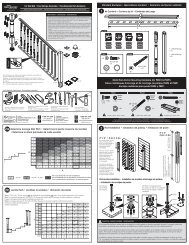
<strong>TAT60</strong> SetupPN 3001 Optional Leg KitNote: Install folding Legs first. Donot open/unfold legs until they aremounted. Lay legs into place exactlyas they come out of the box. Refer toParts List on back page for variouspart names mentioned below.To center of tableInstalling Optional Steel Legs PN 3001I. 1. Screw down 4" x 5" center plate using 4 ea #10 sheet metal screws.2. Screw down 2 pipe brackets using 4 ea #10 sheet metal screws.3. Repeat leg installation on opposite end. Unfold legs and stand unit upright.PipeBracketsRear Fence Lock ScrewII. 1. Remove 5/16-18 hex nut, spring and 5/16-18 thumbscrew from top trackof each rear fence. Slide rear fences outward until hole for thumbscrewsare clear of table.2. Center hex nut over hole in channel of rear fence as shown (right).3. Insert thumbscrew through spring & hole and thread into hex nut. Moverear fences to desired position and tighten thumbscrews.Rear FenceHex NutSaw Track AdjustmentIII. 1. Slide both top decks apart far enough to receive the saw boom. Alignthe pivot block opening on the underside of the boom with the pivotstub on the main deck. Lower the boom onto the pivot stub and rotatethe locking knob clockwise until boom is firmly secured in place. Torelease or rotate the boom, loosen the locking knob counter clockwiseand point the boom in direction of desired cut.Pivot StubSaw Boom2. Loosen acorn nuts on saw track rails (do not remove). Insert saw shoeinto track closest to the saw blade recess in base. Slide opposite trackrail onto saw shoe. Move tracks and saw until saw blade is centeredover recess. Snug acorn nuts and move saw along track to ensure freemovement. If saw binds, loosen acorn nuts and readjust. You may wantto use a square during this step to keep track rails square with rearfence.Do not removehardwareExploded for illustration purposesTilt shoe in and drop through notch3. Trim-A-Table <strong>TAT60</strong> was designed to accommodate most “full-shoe”circular saws on the market. For special situations you can remove or add1/4” shims (PN 7033), to raise or lower the saw tracks to allow your sawblade into the recess. For best results, the teeth of the saw blade shouldbreak the plane of the saw track base slightly, but not cut into the bottomof the recess when moving the saw along the tracks during cut. Note: Addingshims must be done at both ends of base assembly and may requirelonger bolts which are widely available at hardware stores . (page 1)Boom1⁄4" ShimSawBladeRecessPlaneSawBladeRecessSaw BladeEnd View of Track Base(see left)
Saw Track Adjustment (cont.)4. Note: Complete this optional step only if tracks are loweredand additional support under rails is desired. First, notch outeach rear fence to a point even with bottom of rails. Once youare ready to make cuts, position the saw boom at the desiredangle and lock in place (see examples on page 3). Next, looseneach rear fence and position notches under each saw track (tohelp prevent saw tracks from sagging). Remember to loosenrear fences and slide out of the way before repositioning sawboom.Remove NotchUsing Quick-In/Out Feature and Setting Saw Blade DepthIV.Now that your saw freely slides the length of the tracks, youcan quickly remove or insert it by following the followingprocedure: While holding the saw at a slight angle, slide theedge of the saw shoe into the opening of the track and let theopposite edge of the shoe fall into place through the notch.Using the saw’s height adjustment feature, raise or lower theblade to a point where it breaks the plane of the boom’s baseby at least an 1/8 inch (review on page 1).NotchWing Supports, Memory Stops and Butt Stop UseV. To install the wing supports, slide top decks away from sawboom. Align the male tracking nub with the female opening inthe top deck and slide into place. After locking your saw boomto an angle, slide the wing under any material that may overhangthe top decks. Butt stops can be used along the rear fencesor extension rails to provide a convenient means for placingmaterials at a fixed point for repeat cuts. Memory stops can betightened, or loosened on your mark along the saw boom andstop the boom at that point for repeat cutting.Operation & TipsVI. 1.Top decks, rear fences and extensions can all be locked in place using the spring-loaded lockscrews. Wings are designed to be free floating. To start cutting angles, slide tops away from centerand rotate saw boom until the mark on the base is at the desired angle on the protractor. Turn lockingknob clockwise until saw boom is firmly in place. Slide top decks back toward center to takeup any gaps and lock in place. Slide material along the rear fence up to the desired cut. Make cutalong entire cut line remembering to observe all manufacturers safety warnings and pre-cautionswhile operating any, and all related power tools.Saw Boom locked at 45 degrees2. When cutting wide materials extending beyond the support offered by the wings, remove the rear fences. If a special angle is needed,create a template from scrap and draw the angle. Use this to set your saw boom. Periodically check the alignment of your saw boomassembly and re-tighten all fasteners as needed. Memory stops are provided on either side of the boom. Use them as stops to return thesaw boom to a previous angle. Be sure to move the memory stops out of the way when rotating the saw boom.3. When transporting table, loosen locking knob and lift saw boom from pivot stub. Slide top decks and extensions toward center and lockwith thumbscrews. Be careful not to place items on top of table or boom or bang into them as damage can/will occur.
Examples, Using The Protractor12/12 PitchFrom The TopThe <strong>TAT60</strong> protractor uses a split scale which shows both angle degrees and pitch to indicate the same measurement regardless of a left orright saw boom position. As seen above, the red arrows represents a 45° cut, which is equal to a 12/12 pitch, while the yellow represent a3/12 pitch cut. To setup, simply rotate saw boom until the indicator mark on the side of the base aligns with the desired angle then firmlylock saw boom. Note: Always check the mark to ensure correct measurement.3/12 PitchFrom The TopMany roofing & siding profiles today feature 3/12 and even 2/12 pitch designs. These shallow measurements are uniquely capable on your<strong>TAT60</strong> when using either an 8 inch double-lap panel for 2/12, or 12 inch double-lap for 3/12 pitch. Wherever possible, always fit your firstcut to check for accuracy. Extend saw the full length of the panel while cutting.Top DecksSupport Wings (2 total)Break-Down, Transporting & StorageBoom AssemblyRear FencePositioning for Single CarrierCarryingHandleSteel LegsExtensionThe above diagram shows how conveniently your <strong>TAT60</strong> breaks down for transportation and storage. Always transport tool and componentson a level surface and ensure parts will not fall from vehicle while driving. Use Spring Screws to firmly lock extensions and top decks inplace. The saw boom and wings can be tied off in the position seen above. Do not attempt to carry your <strong>TAT60</strong> in this way. Use 2 people orcarry the saw boom and wings with one hand (see inset) and the main tool with the other using the carrying handle provided.
Trim-A-Table <strong>TAT60</strong> SeriesParts ListOrder Early For “Quick Delivery” • Call Toll-Free 1-800 Van Mark • Fax-Free 1-888 Van Mark713306108Stops392238153511-142334See Inset24402919264642471848421451636 53444217413001233209255 extensiontubes not drawn to length49435051372827Terms and Conditions: Prices subject to change without notice. Call for current prices before quoting. Ordersmust include model and serial no in order to guarantee correct parts are shipped. $25.00 minimum order. F.O.B.Farmington Hills, MI. U.S. funds only.Ref Description Qty Req Part # Ref Description Qty Req Part #1 Top, Sliding Table 2 7001 28 Block, Track Riser 2 70492 Deck, Main 1 7002 29 10-24x1/2 Phil Flat 8 20043 Fence, Rear 2 7003 30 1/4-20x3/4 Phil Flat 2 20004 Base, Saw Track 1 7048 33 5/16-18x3/4 Thumb Screw 6 20245 Tube, Extension 4 7052 34 5/16-18x2 Thumb Screw 1 20256 Rail, Saw Track 2 7046 35 1/2-13x2 Soc HD Cap 1 20267 Angle, Extension Cross Bar 2 7007 36 1/4-20x5/8 Phil Pan (F) 2 20338 Angle, Saw Track Cross Bar 2 7050 37 1/4-20x1 1/2 Flat Mach 4 20169 Vinyl, Main Deck 3 7009 38 1/4-20x3/4 Thumb Scr 2 202910 Vinyls, Saw Track 2 7047 39 1/4-20 Square Nut 2 230111-14 Tape Rules, - 4 pc set 1 3408 40 5/16-18 Hex Nut 2 230415 Top, Extension 2 7015 41 3/8-16 Square Nut 1 230516 Stub, Saw Track Pivot 1 7017 42 3/8-16 Hex Nut 3 230617 Block, Saw Track Pivot 1 7018 43 1/4-20 Acorn Nut 4 231918 Rod, Locking 1 7053 44 3/8 Washer Flat 1 250619 Knob, Locking Rod 1 7051 45 1/2 Washer Lock 1 250720 Spring, Screw Retaining 6 7021 46 3/8-16 Nut Acorn 1 231521 Handle, Carrying 1 7022 47 3/8 Washer Lock 1 250822 Stop, Saw Track Angle 2 7023 48 Name Plate 1 702723 Butt-stop, Material 1 7024 49 1/4-20x2 1/4 Truss 4 206424 Protractor Plate 1 7025 50 1/4” Washer, Lock 8 250025 5/16-18 Nut Retaining Brkt 2 7026 51 1/4” Washer, Flat 8 2510Tune Up Kit 3409, Includes: Part #Vinyls, Saw Track - 2 pc Set 3410Tape Rules - 4 pc Set 3408Springs, Thumb Screws 3401Butt-Stop w/Screw 3403Protractor Plate 7025Misc Accessories (not all shown) Part #UniStand AdjustableUSA1Folding Steel Leg Kit 3001Replacement Saw Boom Assy. 3411Thumb Screw Kit 3401Steel LegsPart #300126 Angle, Saw Track Base 2 7032 52 1/4-20 Nut, Hex 4 2300 Saw Horses27 Shim, 1/4” Track Riser 2 7033 53 1/2-13 Nut, Hex 1 2307 Part #3003UniStandPart # USA1Inset52Trim-A-Table_<strong>TAT60</strong>_User<strong>Guide</strong>.indd 16 md/ee 082007 © 2007 Van Mark Products Corp. F604