Reno Loop detector - Gates N Fences
Reno Loop detector - Gates N Fences
Reno Loop detector - Gates N Fences
- No tags were found...

Create successful ePaper yourself
Turn your PDF publications into a flip-book with our unique Google optimized e-Paper software.
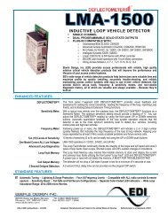
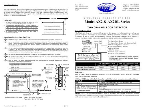
<strong>Loop</strong> InstallationThe vehicle detection characteristics of the inductive loop <strong>detector</strong> are greatly influenced by the loop size andproximity to moving metal objects such as gates. Vehicles such as small motorcycles and high-bed trucks canbe reliably detected if the proper size loop is selected. If the loop is placed too close to a moving metal gate,the <strong>detector</strong> may detect the gate. The diagram below is intended as a reference for the dimensions that willinfluence the detection characteristics.General Rules1. The detection height for a loop is 2/3rds the shortest leg (A orB) of the loop. Example: Short leg = 6’ then Height = 4’.2. As leg A is made longer, the distance C will need to increase.A = 6 ft 9 ft 12 ft 15 ft 18 ft 21 ftC = 3 ft 4 ft 4.5 ft 5 ft 5.5 ft 6 ft3. For reliable detection of small motorcycles, legs A and Bshould not exceed 6 feet.<strong>Loop</strong> Installation - Saw Cut Type1 Mark the loop layout on the pavement. Remove sharp inside corners that can damage the loop wire insulation.2 Set the saw to cut to a depth (typically 2" to 2.5") that insures a minimum of 1" from the top of the wire to pavementsurface. The saw cut width should be larger than the wire diameter to avoid damage to the wire insulation when placed inthe saw slot. Cut the loop and feeder slots. Remove all debris from the saw slot with compressed air. Check that thebottom of the slot is smooth.3 It is highly recommended that a continuous length of wire be used to form the loop and feeder to the <strong>detector</strong>. <strong>Loop</strong> wireis typically 14, 16, 18, or 20 AWG with cross-linked polyethylene insulation. Use a wood stick or roller to insert the wire tothe bottom of the saw slot (do not use sharp objects). Wrap the wire in the loop saw slot until the desired number of turnsis reached. Each turn of wire must lay flat on top of the previous turn.4 The wire must be twisted together a minimum of 6 twists per foot from the end of the saw slot to the <strong>detector</strong>.5 The wire must be held firmly in the slot with 1" pieces of backer rod every 1 to 2 feet. This prevents the wire from floatingwhen the loop sealant is applied.6 Apply the sealant. The sealant selected should have good adhering properties with similar contraction and expansioncharacteristics to that of the pavement material.1LOOP PERIMETER NUMBER OF TURNS10 feet - 13 feet 414 feet - 26 feet 327 feet - 80 feet 281 feet and up 11/8" to 1/4" SAW SLOTTHE WIRE ISCONTINUOUSLY WOUNDIN THE LOOP SAW SLOTFOR THE REQUIREDNUMBER OF TURNS (2turns shown)turn 2turn 1Recommended <strong>Loop</strong> Wire:3FEEDER SLOTREMOVE SHARPINSIDE CORNERSTHE WIRES MUST BETWISTED TOGETHER6 TWISTS PER FOOTFROM THE END OFTHE SAW CUT TOTHE DETECTOR<strong>Reno</strong> LW-120 for 1/8" slots<strong>Reno</strong> LW-116-S for 1/4" slots5SLIDE GATEAA = <strong>Loop</strong> dimension parallel to the gateB = <strong>Loop</strong> dimension perpendicular to the gateC = Distance of the loop from the gate4ROAD SURFACE6 SEALANTBACKER ROD1" piecespaced aboutevery 1'LOOP WIRE3 TURNSEND OF SAW CUT2CBSAW SLOTMIN1"<strong>Reno</strong> A & E4655 Aircenter Circle<strong>Reno</strong>, Nevada 89502U.S.A.Engineering Excellence!O P E R A T I N G I N S T R U C T I O N S F O RModel AX2 & AX2DL SeriesTWO CHANNEL LOOP DETECTORTelephone: (775) 826-2020Facsimile: (775) 826-9191Internet: www.renoae.come-mail: contact@renoae.comGeneral DescriptionThe Model AX2 Series is a two-channel loop <strong>detector</strong> that operates two independent inductive loops andprovides a separate relay output for each channel. The loops connected to channel 1 & 2 are scanned(alternating on and off cycles), which eliminates crosstalk between loops connected to the Model AX2<strong>detector</strong>. The Model AX2DL is factory configured to provide AB and BA directional logic outputs.Model AX2 -xx-xx-x(xx) Two-channel loop <strong>detector</strong>Model AX2DL -xx-xx-x(xx) Two-channel loop <strong>detector</strong> with directional logic3 for 120 VAC NC for Normally Closed Contacts*7 for 24 VAC NO for Normally Open Contacts*8 for 240 VAC blank for Fail-Safe23 for 12 VDC S for Fail-Secure24 for 24 VDC 1C for one 11-pin connector2C for two 11-pin connectorsVerify that source voltage andthe <strong>detector</strong>'s input voltage are* Only the 1C (one connector) models have thethe same before applying power.(NO) Normally Open or (NC) Normally Closedcontact designation.FAIL SAFE OPERATIONPower Failure <strong>Loop</strong> FailureFAIL SECURE OPERATIONPower Failure <strong>Loop</strong> FailureNormally Open Contacts Closed Closed Open OpenNormally Closed Contacts Open Open Closed ClosedIndicatorsPower LED: When the front panel green LED is ON the input power is normal. When the LED is OFFthere is no input power or low power.CH 1 and CH 2 Detect LEDs: Each channel has a red LED to indicate vehicle detection and loop failures.STATUSMEANINGOffNo vehicle present over the loop and the loop is OKSolid OnVehicle present over the loop1 Hz Flashing, 50% duty cycle Shorted loop10 Hz Flashing, 50% duty cycle Open loopIntermittent loop failure. <strong>Loop</strong> failed and corrected.3 Flashes per secondNOTE: When a vehicle is present the LED will be Solid On.IMPORTANT: After installing and applying power to the Model AX2 <strong>detector</strong>, momentarily push theRESET button to clear the Power Down Memory. This initializes the <strong>detector</strong> to the loops that are connectedand clears the memory of any previous loop information.File: Model AX2 Operating Instructions 02-05-01 4 02/05/01
Front Panel Switch FunctionsFrequency (DIP Switches 1 & 2): <strong>Loop</strong>s connected to channels 1 & 2 of a Model AX2 can not crosstalk.When loops are in close proximity to each other and connected to different <strong>detector</strong> units, it may benecessary to select different frequencies for each loop to avoid loop interference. Four Frequency selectionsare available:FREQ Low Med/Low Med/Hi HighSW 1 ON OFF ON OFFSW 2 ON ON OFF OFFNOTE: After changing the frequency, the <strong>detector</strong> must be RESET to obtain reliable operation.Pres/Pulse (DIP Switch 3): Each channel has two modes of operation: either Presence (OFF) or Pulse (ON).When in the OFF position (True Presence mode), the <strong>detector</strong> will hold the Call for as long as the vehicle ispresent in the loop detection area. This is providing that: power is not removed, reset is not applied, normalsize loops are used (approximately 12 ft 2 to 120 ft 2 ), and a normal size vehicle or larger is being detected.When DIP switch 3 is turned ON, the <strong>detector</strong> operates in the PULSE mode and generates a single 250-mspulse output for each vehicle entering the loop detection area.Sensitivity Boost (DIP Switch 4): DIP switch 4 can be turned ON to increase sensitivity only during the“detect state” without changing the sensitivity during the “no detect state.” When a vehicle enters the loop,the <strong>detector</strong> automatically boosts the loop sensitivity. The higher sensitivity level remains in effect until the“detect state” reverts back to the “no detect state.” This feature helps prevent dropouts during the passage ofhigh-bed vehicles and is particularly useful in sliding gate situations.Sensitivity Level: (DIP Switches 5 & 6): Each channel has 4 sensitivity levels. The 2 DIP switches marked5 and 6 select the sensitivity level. The values 1 and 2 that appear to the left of the DIP switches are assignedto a DIP switch when it is turned ON. When a DIP switch is turned OFF, its value is 0. By adding the valuesof each DIP switch that is turned ON, effective values of 0 to 3 can be achieved indicating which of the 4sensitivity levels is selected. Choose the lowest sensitivity level that consistently detects the smallest vehiclenecessary. Do not use a sensitivity level higher than necessary. The following table shows the actualsensitivity for each Sensitivity Level.Sensitivity -∆L/L Switch 5 Switch 60 (Low) 0.32% OFF OFF1 (Med/Low) 0.16% ON OFF2 (Med/High) 0.08% OFF ON3 (High) 0.02% ON ONNOTE: Changing the sensitivitydoes not reset the <strong>detector</strong>. A vehiclecan be over the loop while thesensitivity is being adjusted.Reset Switch: The front panel RESET pushbutton resets both channels. CAUTION: If vehicles are presentin the loops’ detection area, a reset will clear the CALL outputs.Factory Default Settings for Both ChannelsSwitch Factory Default Setting6 OFFSensitivity Level 15 ON4 OFF Sensitivity Boost is Off3 OFF Relay in Presence mode of Operation2 OFFFrequency is High1 OFFOther FeaturesPower Down Memory: When power is removed, the <strong>detector</strong> automatically “remembers” the status of theloop. During the loss of power, vehicles may enter or leave the loop area. When power is restored, the<strong>detector</strong> will output a Call for a vehicle in the loop or No Call for no vehicle in the loop, even if the vehiclesentered or exited the loop while the <strong>detector</strong> was not powered. (Power loss or dips of any duration will notbring a gate arm down onto cars as they wait at the gate). IMPORTANT: After installing and applyingpower to the Model AX2 <strong>detector</strong>, momentarily push the RESET button to clear the Power DownMemory. This initializes the <strong>detector</strong> to the loops that are connected and clears the memory of anyprevious loop information.Failed <strong>Loop</strong> Diagnostics: The Channel DETECT LEDs indicates whether or not the loop is currently withintolerance. If out of tolerance, the LED indicates whether the loop circuit is shorted (1 Hz Flash) or open (10Hz Flash). If and when the loop returns to within tolerance, the Channel DETECT LED will flash at adistinctive rate (a burst of three flashes once per second) to indicate an intermittent loop fault has occurredand corrected. This flash rate will continue (when no vehicles are present in the loop) until another loop faultoccurs or the <strong>detector</strong> is RESET. While indicating an intermittent loop failure, the Channel DETECT LEDswill be steady on to indicate presence of a vehicle. Warning: Removal or loss of power will not clear loopfault memory. The <strong>detector</strong> must be RESET.Wiring InstructionsOne 11-Pin Connector: Requires one <strong>Reno</strong> A & E Model 802-4-2TP HarnessPIN WIRE COLOR FUNCTION for (NO) Models FUNCTION for (NC) Models1 BLACK POWER, HOT or (+) POWER, HOT or (+)2 WHITE POWER, NEUTRAL or (-) POWER, NEUTRAL or (-)3 ORANGE Ch. 2 Relay Normally Open Ch. 2 Relay Normally Closed4 GREEN No connection No connection5 YELLOW Ch. 1 Relay Common Ch. 1 Relay Common6 BLUE Ch. 1 Relay Normally Open Ch. 1 Relay Normally Closed7 GRAY Ch. 1 <strong>Loop</strong> Ch. 1 <strong>Loop</strong>8 BROWN Ch. 1 <strong>Loop</strong> Ch. 1 <strong>Loop</strong>9 RED Ch. 2 Relay Common Ch. 2 Relay Common10VIOLET, orWHITE/BLACKCh. 2 <strong>Loop</strong>Ch. 2 <strong>Loop</strong>11WHITE/GREEN,or WHITE/REDCh. 2 <strong>Loop</strong>Ch. 2 <strong>Loop</strong>Two 11-Pin Connectors: Requires two <strong>Reno</strong> A & E Model 802-4 HarnessesPIN COLOR CONNECTOR 1 FUNCTION CONNECTOR 2 FUNCTION1 BLACK POWER, HOT or (+) No connection2 WHITE POWER, NEUTRAL or (-) No connection3 ORANGE No connection No connection4 GREEN No connection No connection5 YELLOW Ch. 1 Relay Common Ch. 2 Relay Common6 BLUE Ch. 1 Relay Normally Open Ch. 2 Relay Normally Open7 GRAY Ch. 1 <strong>Loop</strong> Ch. 2 <strong>Loop</strong>8 BROWN Ch. 1 <strong>Loop</strong> Ch. 2 <strong>Loop</strong>9 RED No connection No connection10VIOLET, orWHITE/BLACKCh. 1 Relay Normally Closed Ch. 2 Relay Normally Closed11WHITE/GREEN,or WHITE/REDNo connectionNo connectionNOTE: All contacts above are shown for power applied, loops connected, and no vehicle present.Model AX2DL Directional Logic: Uses the Ch. 1 and Ch. .2 loops to determine the direction the vehicle istraveling. The loops must spaced such that a vehicle can span both loops. The expected installation is twoloops, one after the other in the same lane, spaced anywhere from overlapping to 6 feet apart. NOTE:Contact a Field Engineer at <strong>Reno</strong> A & E regarding loop configurations and spacings for specificapplications.When a vehicle enters the first loop the CH LED will flash 750 ms ON and 250 ms OFF to indicate thevehicle’s presence. The flash will continue until the vehicle leaves the loop area. When the directionaloutput is set to the pulse mode, the CH LED will flash 250 ms ON and 750 ms OFF to indicate the vehicle’spresence over the second loop. This indication will continue until the vehicle leaves the loop.CH 1 LOOPAB DirectionCH 2 LOOPWhen a vehicle travels from CH 1 loop andenters the CH 2 loop, the CH 2 relay andLED activate to indicate the AB direction.2 3CH 1 LOOPBA DirectionCH 2 LOOPWhen a vehicle travels from CH 2 loop andenters the CH 1 loop, the CH 1 relay andLED activate to indicate the BA direction.