- Page 1 and 2: 2RBF The National Water Research In
- Page 3 and 4: Published by the NATIONAL WATER RES
- Page 6: Foreword In 1999, the National Wate
- Page 9 and 10: vi 1:30 pm Session 3B: Hydraulic As
- Page 11 and 12: viii 1:15 pm Session 8: Emerging Co
- Page 14 and 15: Acronyms ADA ß-alaninediacetic aci
- Page 16: Conference Abstracts
- Page 19 and 20: 2 conventional treatment train on c
- Page 21 and 22: 4 The Louisville Water Company also
- Page 23 and 24: 6 Treatment Capital Cost Annual O&M
- Page 25: 8 design engineers needed to addres
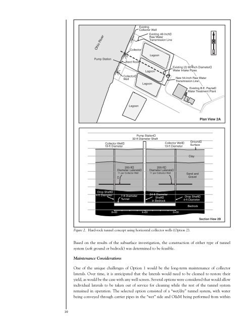
- Page 29 and 30: 12 Figure 4. Wet/dry tunnel concept
- Page 31 and 32: 14 The turbidity of well water is t
- Page 34 and 35: Session 2: Operations Construction
- Page 36 and 37: Land Surface lengths of well screen
- Page 38: Summary Well systems can be constru
- Page 41 and 42: 24 Traditionally, ASR has been used
- Page 43 and 44: 26 plans for a pilot-scale bank-fil
- Page 46 and 47: Session 2: Operations Evolution fro
- Page 48 and 49: Today, Cedar Rapids obtains all of
- Page 50: REFERENCES AND ACKNOWLEDGEMENTS The
- Page 53 and 54: 36 source of most nitrate detected
- Page 55 and 56: 38 Hallberg, G.R., D.G. Riley, J.R.
- Page 57 and 58: 40 Two 10-MGD capacity pumps were i
- Page 60 and 61: Session 3: Hydraulic Aspects Pluggi
- Page 62 and 63: iverbed scouring. This analysis sho
- Page 64: REFERENCES Schafer, D.C. (2003).
- Page 67 and 68: 50 TS GWA Tegel TS Wannsee TS Tegel
- Page 69 and 70: 52 contains the lowest concentratio
- Page 71 and 72: 54 δ 18 O [ 0⁄00 versus Standard
- Page 73 and 74: 56 Acknowledgements We would like t
- Page 75 and 76: 58 Phase 1 Investigations Once the
- Page 77 and 78:
60 pumping is discontinued and the
- Page 80 and 81:
Session 4: Siting Water-Quality Man
- Page 82 and 83:
Torgau Case Study The highly produc
- Page 84 and 85:
The mean concentration in the “mi
- Page 86 and 87:
Session 5: Dynamics Using Models to
- Page 88 and 89:
source of induced infiltration to t
- Page 90 and 91:
affect the amount of contaminant en
- Page 92 and 93:
intuitive system behavior. In the c
- Page 94 and 95:
entering the well can be carried ou
- Page 96:
Ray, C., T.W. Soong, Y.Q. Lian, and
- Page 99 and 100:
82 Riverbank Filtration Near Torgau
- Page 101 and 102:
84 drinking-water quality. Drinking
- Page 104 and 105:
Session 5: Dynamics Temporal Change
- Page 106 and 107:
• Equalization of fluctuating con
- Page 108 and 109:
Session 5: Dynamics An Update of th
- Page 110 and 111:
Session 5: Dynamics On Bank Filtrat
- Page 112 and 113:
Figure 2. Streamlines for two wells
- Page 114 and 115:
well galleries near the Unterhavel
- Page 116 and 117:
Dinner Presentation Hydraulic Sensi
- Page 118 and 119:
conductivity k (especially of the r
- Page 120 and 121:
parameter value: Figure 6. Initial
- Page 122 and 123:
Keynote Presentation Riverbank Filt
- Page 124 and 125:
esulted in a significant improvemen
- Page 126 and 127:
Fritz, B. (2002). Uferfiltration un
- Page 128 and 129:
Session 6: Microorganisms Using Mic
- Page 130 and 131:
was independent of finished water t
- Page 132 and 133:
Session 6: Microorganisms Transport
- Page 134 and 135:
Session 6: Microorganisms Laborator
- Page 136 and 137:
Cryptosporidium are unreliable, lab
- Page 138 and 139:
Pathogen Concentration (pathogens/1
- Page 140 and 141:
Session 6: Microorganisms Fate of D
- Page 142 and 143:
treatment train optimized for turbi
- Page 144 and 145:
Acknowledgements We gratefully ackn
- Page 146 and 147:
Session 6: Microorganisms Assessmen
- Page 148 and 149:
screens along the entire lateral le
- Page 150 and 151:
Table 3. Average Distribution of Ri
- Page 152 and 153:
Location Number of Sampling Events
- Page 154 and 155:
Session 7: Organics Removal Riverba
- Page 156 and 157:
uncontaminated groundwater could le
- Page 158 and 159:
Sacher, F., H.-J. Brauch, and W. K
- Page 160 and 161:
Session 7: Organics Removal Organic
- Page 162 and 163:
TOC (mg/L) 9 8 7 6 5 4 3 2 1 Site 1
- Page 164 and 165:
Conclusions RBF is very effective i
- Page 166 and 167:
Lunch Presentation Potential Uses o
- Page 168 and 169:
Session 8: Emerging Contaminants Re
- Page 170 and 171:
H 3C O O N N H3C N CH3 Cl AMDOPH Be
- Page 172 and 173:
Session 8: Emerging Contaminants Re
- Page 174 and 175:
Results and Conclusion The Santa An
- Page 176 and 177:
Session 8: Emerging Contaminants Re
- Page 178 and 179:
echarge is not well understood. Our
- Page 180 and 181:
Session 8: Emerging Contaminants Re
- Page 182 and 183:
The MS conditions were as follows:
- Page 184 and 185:
Session 9: Public Policy and Regula
- Page 186 and 187:
FEET 1,000 900 800 700 600 VERTICAL
- Page 188 and 189:
The surficial aquifers in Midwester
- Page 190 and 191:
Session 9: Public Policy and Regula
- Page 192 and 193:
Session 9: Public Policy and Regula
- Page 194 and 195:
that multiple samples should be eva
- Page 196 and 197:
turbidity. Endospores, Giardia, Cry
- Page 198 and 199:
Session 9: Public Policy and Regist
- Page 200 and 201:
For the first phase of the Dyje Pro
- Page 202 and 203:
Concentration mg.l 1 60 50 40 30 20
- Page 204 and 205:
Session 11: Case Studies “Lessons
- Page 206 and 207:
Concentration (mg/L) 35 30 25 20 15
- Page 208 and 209:
REFERENCE Koterba, M.T, F.D. Wilde,
- Page 210 and 211:
Session 11: Case Studies “Lessons
- Page 212 and 213:
REFERENCES Laszlo , F., and Z. Homo
- Page 214 and 215:
Session 11: Case Studies “Lessons
- Page 216 and 217:
Figure 2. A sketch of the study are
- Page 218 and 219:
By analyzing the δ 15 N-NO 3 of si
- Page 220 and 221:
Session 11: Case Studies “Lessons
- Page 222 and 223:
Microbial growth was weak in all la
- Page 224 and 225:
Session 11: Case Studies “Lessons
- Page 226 and 227:
Objectives The aim of the study was
- Page 228 and 229:
6000 4000 2000 Suspended Solids (mg
- Page 230 and 231:
REFERENCES American Public Health A
- Page 232 and 233:
Session 11: Case Studies “Lessons