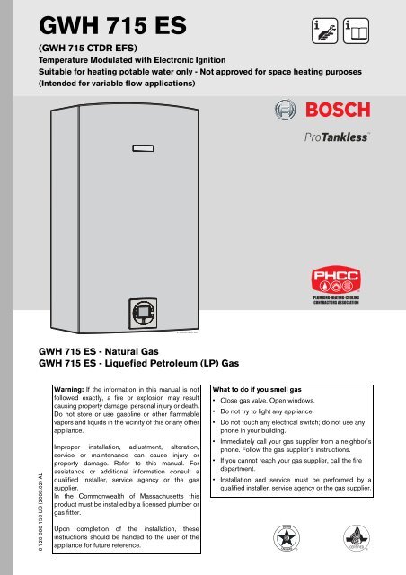
Owner's Manual Bosch GWH715ES
Owner's Manual Bosch GWH715ES
Owner's Manual Bosch GWH715ES

You also want an ePaper? Increase the reach of your titles
YUMPU automatically turns print PDFs into web optimized ePapers that Google loves.
IndexIndex1 Warning 32 Appliance details 42.1 Features 42.2 GWH 715 ES Specifications (Technical data) 42.3 Unpacking the GWH 715 ES heater 52.4 General rules to follow for safe operation 62.5 Dimensions and Minimum installationclearances 73 Installation instructions 83.1 Tools required for installation 83.2 Introduction 83.3 Proper location for installing your heater 83.4 Heater placement and clearances 83.5 Mounting installation 83.6 Gas piping & connections 103.7 Water connections 123.8 Water quality 123.9 Recirculation application 133.10 Combustion air requirements 133.11 Venting 153.12 Measuring gas pressure 244 Electrical connections 254.1 Electrical power supply 254.2 Position of the fuses in control unit 255 Operation instructions 265.1 Description LCD display 265.2 For your safety read before operatingyour water heater 275.3 Power 275.4 Temperature selection 275.5 Use of optional remote control accessory(part no. TSTAT2) 285.6 Operation 285.7 Reset button 285.8 Program button 285.9 Locked condition 286 Maintenance and service 296.1 Annual maintenance 296.2 Winterizing for seasonal use 296.3 Mineral scale build-up 306.4 Adjusting CO2 306.5 Program values 336.6 Control board diagnostics 347 Troubleshooting 357.1 Introduction 357.2 Burner do not ignite when hot wateris turned ON 357.3 Water is too hot 357.4 Water is not hot enough 357.5 Low water flow/pressure 367.6 Hot water temperature fluctuates at tap 367.7 Noisy burner/heater during operation 368 Problem solving 388.1 Error code diagnostics 389 Electrical diagram 4210 Sensor resistance charts 4311 GWH 715 ES Functional scheme 4512 Interior components diagramand parts list 4612.1 Interior components 4612.2 Components diagram 4813 Protecting the environment 5414 Limited Warranty 5526 720 608 158
Warning1 WarningFor your safetyDo not store or use gasoline or other flammable,combustible or corrosive vapors and liquids in thevicinity of this or any other appliance.Warning: Carefully plan where youinstall the heater. Correct combustionair supply and flue pipe installation arevery important. If a gas appliance is notinstalled correctly, fatal accidents canresult, such as carbon monoxidemonoxide poisoning or fire.FCC:This device complies with Part 15 of the FCC rules.Operation is subject to the following two conditions: (1)This device may not cause harmful interference, and (2)this device must accept any interference received,including interference that may cause undesiredoperation.Warning: Exhaust gas must be ventedto outside using stainless steel ventmaterial suitable for category III ventsystems and temperatures up to 480°F.Vent piping must be sealed gas-tight toprevent possibility of flue gas spillage,carbon monoxide emissions and risk offire, resulting in severe personal injuryor death. Approved vent terminatorsmust be used when penetrating to theoutside.Warning: Place the heater in a locationwhere water leaks will do NO DAMAGEto adjacent areas or lower floors.Warning: Field wiring connections andelectrical grounding must comply withlocal codes, or in the absence of localcodes, with the latest edition of theNational Electric Code, ANSI/NFPA 70,or in Canada, all electrical wiring mustcomply with the local codes and theCanadian Electrical Code, CSA C22.1Part 1.Fig. 1Warning: Shock hazard: line voltage ispresent. Before servicing the waterheater, unplug power supply cord fromoutlet. Failure to do so could result insevere personal injury or death.Warning: The heater must bedisconnected from the gas supplypiping system during any pressuretesting of that system at test pressuresequal to or more than 0.5 psig.6 720 608 1583
Appliance details2 Appliance details2.1 FeaturesParts• Key Pad interface control• High power pre-mix compact burner with low NOxemissions• Modulating Gas Valve with constant gas:air ratiocontrol• Modulating water valve for improved comfort andtemperature control.High quality materials for long working life• Copper heat exchanger• High efficiency Ceramat Burner• Compact space saver: mounts on a wall with asupplied bracket.Features• Real-time diagnostics for troubleshooting/informational purposes• LCD Display with backlight• On/Off and Temperature control switches• Reset button• Program button (Selectable temperature default)• Failure codes for easy diagnostics and repair• Easily removable one-piece cover.Accessories (<strong>Bosch</strong> part #)• Optional wireless remote control accessory tooperate with the appliance (TSTAT2)• Cascading kit (TLINK)• Outdoor kit (PTOK)• External water filter (8703305356).iBOSCH is constantly improving itsproducts, therefore specifications aresubject to change without prior notice.2.2 GWH 715 ES Specifications(Technical data)Approved in US/CanadaCapacityMaximum flow rate: 7.3 GPM (27 l/min) at a 45°F(25°C) rise.Maximum output160,500 Btu/h (47.0 kW)Maximum input199,000 Btu/h (58.3 kW)Efficiency in %Thermal efficiency > 82%Min. Input19,900 Btu/h (5.8 kW)Temperature ControlSelection range: 100°F (38°C) - 140°F (60°C)Default temperature: 122°F (50°C)Stability: +/- 2°F (+/- 1°C)Gas RequirementGas connection (inches) - ¾”Inlet gas pressure under operation (with a high hotwater flow rate)*• Propane: 8” - 13” water column• Natural Gas: 3.5” - 10.5” water column.* To measure gas pressure, see Measuring GasPressure, chapter 3.12, page 24.Water• Hot water connection (inches) - ¾”• Cold water connection (inches) - ¾”• Water valve material: Polymer (PPS) (PolypropyleneSulfid)• Minimum water flow: 0.65 gallon/minute (2,5 l/m).Note: Activation varies with inlet water temperaturesfrom 0.65 - 1.6 gallon/minute (2.5 - 6.1 l/m).• Minimum recommended water pressure: 30 PSI(2.07 bar).• Minimum well pressure 40 psi, see page 12.• Connections:– Bottom of heater46 720 608 158
Appliance detailsCombustion• NOx ≤ 55 ppm• CO ≤ 250 ppm (measured)• CO 2 level set from factory, see chapter 6.4, page 30.Dimensions• Depth (in): 11¼” (286 mm)• Width (in): 17 7 / 8 ” (452 mm)• Height (in): 30½” (775 mm)• Weight: 67 pounds (30.5 kg).2.3 Unpacking the GWH 715 ES heaterBefore installing the unit, be certain you have thecorrect heater for your type of Gas: Propane orNatural Gas. Identification labels are found on theshipping box, and on the rating plate which is located onthe right side panel of the cover.Gas typesNatural Gas.LP Gas.Voltage120 V AC (60 Hz) nominalAmperageIdle - 40 mAOperation - ≤ 2.5 ANoise45 - 65 db (A)Safety devices• Flame failure device (ionization flame rod sensor)• Pressure relief valve (supplied with heater)• Over heat prevention (temperature limiter)• Inlet temperature sensor• Outlet temperature sensor• Back flow temperature sensor.Water protectionIP X4 (protection against water drops)iIf appliance is installed at elevationsbetween 2000ft and 4500ft, acombustion gas analyzer is required forproper calibration of appliance. (see page24).Fig. 2ABRating plateSerial numberType of gasThe box includes:• GWH 715 ES• Pressure relief valve (150 psi / 200,000 Btu rating)• Bracket for wall hanging the heater• Exhaust vent adaptor (with 4 screws and gasketprovided)• Combustion air inlet adaptor (with 3 screws and gasketprovided)• Installation manual (manual can be downloaded atwww.boschpro.com)• Product registration card• Energy Guide label.Please complete and return the enclosed productregistration card.The GWH 715 ES is not approved or designed for:• Manufactured (mobile) homes, boats or anymobile installation.• Use above 4500ft A.S.L. altitude.• Outdoor installation without installation ofOutdoor kit (PTOK).• Applications where inlet water temperature ishigher than 140ºF (60°C). A 3-way valve ormixing valve must be installed before theappliance if inlet water temperature exceedsthis limit.• Space heating purposes.6 720 608 1585
Appliance detailsTo remove front coverB Loosen the two Philips head screws located onbottom rear of cover (see Fig. 3).Fig. 3 Loosen the two screwsB Lift front cover panel upward and remove.Fig. 4Remove the front coverTo remove combustion cover (service only)B Open the four clips and remove the combustioncover see Fig. 5.Fig. 5Remove the combustion cover2.4 General rules to follow for safeoperationB 1. You must follow these instructions when you installyour heater. In the United States: The installation mustconform with local codes or, in the absence of localcodes, the National Fuel Gas Code ANSI Z223.1/NFPA 54.In Canada: The Installation must conform with CGAB149.(1,2) INSTALLATION CODES and /or localinstallation codes.B 2. Carefully plan where you install the heater. Correctcombustion air supply and vent pipe installation arevery important. If not installed correctly, fatalaccidents can occur, such as carbon monoxidepoisoning or fire.B 3. When the unit is installed indoors and ROOMSEALED (twin pipe) it is permitted to be located inbathrooms, bedrooms and occupied rooms that arenormally kept closed. See chapter 3.11 (page 15). Ifthe unit will be installed indoors and use indoorcombustion air, the place where you install the heatermust have enough ventilation. The National FuelGas Code does not allow UNSEALED gas firedwater heater installations in bathrooms,bedrooms or any occupied rooms normallykept closed. See chapter 3.3, page 8 and 3.10,page 13.B 4. You must vent your heater. See chapter 3.11, page15 on VENTING.B 5. The appliance and its gas connection must be leaktested before placing the appliance in operation.The appliance must be isolated from the gas supplypiping system by closing its individual manual gasshutoff valve (not supplied with heater) during anypressure testing at pressures in excess of ½ Psig (3.5kPa).B 6. Keep water heater area clear and free fromcombustibles and flammable liquids. Do not locatethe heater over any material which might burn.B 7. Correct gas pressure is critical for the properoperation of this heater. Gas piping must be sized toprovide the required pressure at the maximum outputof the heater, while all the other gas appliances are inoperation. Check with your local gas supplier, andsee the section on connecting the gas supply, seechapter 3.6.B 8. Should overheating occur or the gas supply fail toshut off, turn off the gas supply at the manual gas shutoff valve, on the gas line. Note: manual gas shutoffvalve is not supplied with the heater but must be fieldinstalled.B 9. Do not use this appliance if any part has beenunderwater. Immediately call a qualified servicetechnician to inspect the appliance and to replace anypart of the control system and any gas control whichhas been underwater.B 10. Failure to install heater correctly may lead tounsafe operation and void the warranty.66 720 608 158
Appliance details2.5 Dimensions and Minimum installation clearancesFig. 6Dimensions1 On/Off button2 Reset button3 Program key4 Power ON or stand-by LED5 LCD display6 Up button7 Down buttonModel GWH 715 ESTOP (A) 12”FRONT (B) 1”BACK 0”SIDES 1”FLOOR (C) 12”VENT DIAMETER 3”VENT CLEARANCES 1”Table 1 Minimum clearancesNote: Vent clearances vary per manufacturer. Consultvent manufacturer for specific clearance information.Fig. 7Minimum clearancesNote: For servicing access, a 2ft clearance to frontcover is recommended.6 720 608 1587
Installation instructions3 Installation instructions3.1 Tools required for installation• Philips head screwdriver• Flat head screwdriver• Adjustable wrench• Level• Thermometer• Standard plumbing tools• Manometer.3.2 IntroductionPlease follow these instructions. Failure to followinstructions may result in:B Damage or injury.B Improper operation.B Loss of warranty.If you are unable to perform the tasks required to installthis heater properly, please contact a locally licensedplumber or gas technician.3.3 Proper location for installing yourheaterCarefully select the location of the water heater. Foryour safety and for proper heater operation, you mustprovide combustion air to the heater and a properexhaust vent system.Follow the guidelines below:B 1. Locate the heater where venting, gas andplumbing connections are feasible and convenient.B 2. The hot water lines should be kept short andinsulated to save energy. Centrally locating the waterheater is recommended to keep hot waterdistribution times even throughout the structure.Warning: The water in this waterheater is cold and always remains coldexcept for the times the burner is on. Inthe event of power outage inconjunction with freezing temperatures,it is recommended that the heater bedrained.See chapter 6.2, page 29 “Winterizing”for draining instructions.Warning: Flammable materials,gasoline, pressurized containers, or anyother items or articles that are potentialfire hazards must NOT be placed on oradjacent to the heater. The appliancearea must be kept free of allcombustible materials, gasoline andother flammable vapors and liquids.3.4 Heater placement and clearancesThe GWH 715 ES is approved for installation on acombustible wall (see chapter 3.5 Mountinginstallation) provided the floor covering belowthe heater is noncombustible. For installations in analcove or closet, maintain the minimum clearances tocombustible and non-combustible materials listedbelow. See also Fig. 7.A. Top 12 inches (306 mm)B. Front 1 inches (25 mm)C. Back 0 inchesD. Sides 1 inches (25 mm)E. Bottom 12 inches (306 mm)Clearances from any exhaust vent pipe are dependentupon the clearance requirements of the stainless steelvent pipe manufacturer. Single wall stainless steel(AL29-4C) vent pipe (vent type rated for Category IIIappliances) must be used when exhaust venting thisappliance. See chapter 3.11 (page 15) Venting.3.5 Mounting installationiWarning: before startinginstallationB Check that there are no loose partsinside the applianceB Confirm the gas type of the heatermatches the gas supply you will beconnecting the heater, see Fig. 2,page 5.B Ensure that gas pipe, gas valve,mixer, fans and burner have nodamage and are properly fitted.Front cover should be removed (seeinstructions on page 6) in order to inspectcomponents visually.Warning: Do not install this applianceon a carpeted wall. The heater must bemounted on a wall using appropriateanchoring materials.86 720 608 158
Installation instructionsIf wall is sheathed with plaster or drywall, it isrecommended that two support boards, either 1”x4” or1/2" (minimum) plywood first be attached across a pairof studs, see Fig. 8, page 9.B Secure the wall mounting bracket provided with theheater to the wall surface. The heater must be keptlevel on the wall surface, see Fig. 9, page 9.B Hang the appliance on the bracket, see Fig. 10, page9.Studs 16"(406mm) oncenterFig. 10 Mounting the heaterWarning: Appliance must be installedvertically.Fig. 8Distance between support boardsFig. 9Leveling the mounting bracket on the studs6 720 608 1589
Installation instructions3.6 Gas piping & connectionsBefore connecting the gas supply, check the ratingplate on the right side of the heater to be sure that theheater is rated for the same gas to which it will beconnected.In the United States: The installation must conform withlocal codes or, in the absence of local codes, theNational Fuel Gas Code ANSI Z223.1/NFPA 54.In Canada: The Installation must conform to CSA B149INSTALLATION CODES and/or local installationcodes.Warning: DO NOT connect to anunregulated or high pressure propaneline or to a high pressure commercialnatural gas line.Warning: The heater must be isolatedfrom the gas supply piping systemduring any pressure testing of thatsystem at test pressures equal to ormore than 0.5 psig. If overpressure hasoccurred, such as through impropertesting of the gas lines or malfunction ofthe supply system, the gas valve mustbe checked for safe operation.Once connections are made, check for gas leaks at alljoints. Apply some gas leak detection solution to all gasfittings. Bubbles are a sign of a leak. A combustible gasdetector may also be used to detect for leaks.Danger: If you have a leak, shut off thegas. Tighten appropriate fittings to stopleak. Turn the gas on and check againwith a gas leak detection solution.Never test for gas leaks using a matchor flame.GAS LINE SIZINGThe gas supply piping for a single heater should besized for a maximum draw of 199,000 BTUH. Measurethe length of gas supply line and use the tables inFig. 13, page 11 or the gas line manufacturer’s sizingtables to determine the pipe diameter necessary toaccommodate the 199,000 BTU demand of the heater.If there are more gas appliances on the line, size the gasline according to the total maximum amount of BTUinput rating for all appliances.Note: Undersizing the gas line may result in diminishedhot water flow rate and temperature. See chapter 3.12,page 24 for the procedure to confirm gas pressure.Proper gas pressure must be confirmed at time ofinstallation.GAS CONNECTIONSB Install a manual gas shut off valve on the gas supplyline.B Install a union when connecting gas supply.B The minimum internal diameter required forany appliance connector is ¾”, see Fig. 13 formore details on pipe sizing.B National Fuel Gas Code requires that a sedimenttrap (drip leg) be installed on gas appliances not soequipped. The drip leg must be accessible and notsubject to freezing conditions. Install in accordancewith the recommendations of the serving gassupplier, see Fig. 11.Gas pipingInlet gas particle screen(included)Fig. 12Minimum3”CapGas supplyFig. 11 Gas connection (drip leg)106 720 608 158
Installation instructions3.7 Water connectionsWarning: This heater is not approvedfor preheated water applications above140°F (60°C). See chapter 3.9 forapproved recirculating application.B When facing the heater, the ¾” cold connection is onthe bottom right and the hot connection is on thebottom left. Centrally locating the water heater isrecommended to keep hot water distribution timeseven throughout the structure.B Never sweat any piping directly to or beneaththe water connections, as damage can occur tothe internal water valve from heating of thepipe.B Keep water inlet and outlet pipes to no lessthan ¾" (19.05mm) diameter to allow the fullflow capacity.B If the cold and hot connections to the heater arereversed, the heater will not function. Be certain thereare no loose particles or dirt in the piping. Blow outor flush the lines before connecting to the waterheater.B Full port shutoff valves should be installed on boththe cold water supply and hot water outlet lines tofacilitate servicing the heater (see Fig. 16).B For installation on a private well system with the useof a pressure tank, the lowest pressure range settingrecommended is 40-60 psi (2.75 and 4.15 bar).Fig. 14HOTCOLD3.8 Water qualityWater quality can have an impact on appliancelongevity and may not be covered under themanufacturer's warranty.For water analysis data call your local water department,or if on a well, have well water analyzed periodically. Ifwater quality exceeds one or more of the valuesspecified below, <strong>Bosch</strong> recommends installing a waterconditioner or softener.DescriptionMax. LevelspH pH 6.5 - 8.5TDS (total DissolvedSolids)Total hardnessmg/l or ppm 500mg/l or ppm100(6 grains)Aluminum mg/l or ppm 2.0Fig. 15 Water filter1 Water valve with engine2 Water filterB The use of unions when connecting both waterpipes to the inlet and outlet connections isrequired. This will facilitate any necessaryservicing.B Plastic or PEX type plumbing line materials are notsuitable for connecting directly to the water heater.B Although water piping throughout the building maybe other than copper, we recommend that copper orsuitably rated stainless steel flex line piping be usedfor the water connections for 1.5’ on either side ofthe water heater (follow local codes if morestringent).Chlorides mg/l or ppm 250Copper mg/l or ppm 1.0Iron mg/l or ppm 0.3Manganese mg/l or ppm 0.05Zinc mg/l or ppm 5.0Table 2126 720 608 158
Installation instructionsConnecting the pressure relief valve (PRV)A listed pressure relief valve supplied with the heatermust be installed at the time of installation. No valve isto be placed between the PRV and the heater. Noreducing coupling or other restriction may be installedin the discharge line. The discharge line must be aminimum of 4” above a drain and installed such that itallows complete drainage of both the PRV and the line.The discharge line must be placed where it will notcause any damage.The location of the PRV must be readily accessible forservicing or replacement, and be mounted as close tothe water heater as possible. See Fig. 16. To install thePRV, a suitable fitting connected to an extension on a“T” fitting can be sweated to the hot water line.Support all piping.3.9 Recirculation applicationThe GWH 715 ES Protankless water heater isapproved for domestic hot water recirculation. Thefollowing drawing is provided to outline one possiblerecirculation design using the water heater inconjunction with an Ariston mini tank water heater.Recirculation directly through the tankless water heateris also allowed. This schematic is for illustration only andmust not be used for actual installation withoutappropriate engineering and technical advice from aproperly licensed professional in the locality where theinstallation is made.<strong>GWH715ES</strong>Ariston MinitankFig. 17 Recirculation applicationFig. 16 Plumbing Connections (with shutoff valves)and Pressure Relief ValveWarning:In applications where inlet watertemperature can exceed 140°F (60ºC), a3-way valve or mixing valve must beinstalled before the appliance to preventwater exceeding 140°F (60°C) fromentering the appliance.1 Full port isolation valve2 Circulator (pump on timer)3 Check valve4 PRV5 Expansion tankThe use of a small electric mini-tank water heater (4-6gallon size) should be used for this application anddesigned so the pump will circulate the water throughthe mini-tank and the building's hot water return looponly. Timed or thermostatically controlled operation ofthe pump is commonly done. Contact <strong>Bosch</strong> WaterHeating if further information is needed.3.10 Combustion air requirementsWarning: In areas where outsidetemperatures routinely come close tofreezing, sealed combustion operationis required. Use a concentrictermination or separate terminations forcombustion and vent, which must beinstalled on the same wall or roofsurface, however never facing thedirection of prevailing winds. Failure todo so may result in heat exchangerfreezing up and bursting. This failure isnot covered under the manufacturer'swarranty.6 720 608 15813
Installation instructionsWarning: When installed in anenvironment where corrosive chemicalsor dirty air are present the twin pipesystem is required.Twin pipeThe GWH 715 ES is designed as a sealed combustionappliance. It is recommended that the combustion airbe provided by a dedicated 3” or 4” pipe from theoutside. The combustion air pipe may be PVC or anyother rigid or semi rigid sealed 3” or 4” pipe. Thecombustion air inlet, whether terminating vertically orhorizontally, must be located in such a manner asto provide a minimum 3 foot clearance from theexhaust vent terminator. See Fig. 28 Letter I, page21.The maximum length of the combustion air inletis 26 feet with one elbow. Subtract 2.5 feet foreach additional 90° elbow and 1.25 feet for eachadditional 45° elbow. Maximum number ofelbows permitted is 3.Warning: Terminations must preventrain and debris from entering thecombustion air and exhaust vent piping.Single pipeNote: This appliance requires 9950 cubic feet ofavailable combustion air, or a minimum of 1243 squarefeet of space with an 8 foot ceiling to operate. If thelarge amount of air space, which equates to about halfof most average sized homes, is not available, theappliance must pull air from the outside (see twin pipeabove).Although it is permissible to draw combustion air frominside the structure, it is not the manufacturer’srecommended installation method. Always install a 3inch elbow on the top of the combustion air inletadaptor to prevent foreign objects from falling into theunit.If a single pipe installation is utilized, follow guidelinesbelow for providing adequate combustion air for thewater heater as well as any other appliances that mayconsume air in the space. Always follow local codes ifthey are more stringent.This Installation <strong>Manual</strong> specifies the minimum verticalvent pipe and the amount of combustion air required forthis unit. When all requirements are followed, the unitwill operate properly and safely. However, there may stillbe a risk of freezing due to negative draft if the othercombustion appliances in the building are not suppliedwith sufficient combustion air. A wood stove or furnacecan pull its combustion air from the heater's vent pipe,allowing the cold incoming air to freeze the cold waterin the heat exchanger. Supplying more combustion airfor all combustion appliances is the solution. A HVACspecialist should be consulted to design solutions forproviding more combustion air.Observe the following guidelines:Installations in structures that have been tightlyconstructed (air infiltration rate of 0.40 ACH or less)must be provided with combustion air per the NationalFuel Gas Code. Consult a HVAC specialist if your airinfiltration rate is questionable.The space must have two permanent openings, onecommencing within 12 inches of the top and onecommencing within 12 inches of the bottom of theenclosure.Each opening must have a minimum free area of onesquare inch per:• 1000Btu/hr if all air is taken from inside the building• 2000Btu/hr if all air is taken from the outside byhorizontal ducts• 4000Btu/hr if all air is taken from the outside bydirect openings or vertical ducts.Or the space must be provided with one permanentopening or duct that is within 12 inches of the ceiling ofthe enclosure.This opening must have a minimum free area of onesquare inch per:• 3000Btu/hr if all air is taken from the outside by adirect opening or vertical duct.146 720 608 158
Installation instructions3.11 Venting 3.11.1 Vent material and specificationsWarning: Do not reduce the vent(exhaust and combustion) pipe sizesand do not common vent with any othervented appliance or stove.Establish vent clearances that comply with the ventmanufacturer's specifications. In all cases, follow localcodes. See Table 3.Diam.Min.lenghtMax.lengthMaterialWarning: Failure to vent the exhaustgases to the outside with sealedstainless steel vent pipe (AL29-4C)may result in dangerous flue gasesfilling the structure in which it isinstalled.ExhaustVentIntakeVent3 or 4inches3 or 4inches3 feet 26 feet with1 90° elbowand terminal1 90°elbow26 feet with1 90°elbowand terminalSealed single wallstainless steel(AL29-4C)Sealed PVC orany other rigid orsemi rigid pipeWarning: Do not mix vent pipe orjoining methods from differentmanufacturers.Warning: Proper end terminal / raincap must be used. Failure to do so mayresult in damage to the appliance.This damage is not covered underthe manufacturer's warranty.Caution: The vent system must beinstalled by a qualified installer inaccordance with these instructions. Ifimproperly installed, a hazardouscondition such as explosion or carbonmonoxide poisoning could result.<strong>Bosch</strong> Water Heating will not beresponsible for improperly installedappliances.Warning: In areas where outsidetemperatures routinely come close tofreezing, sealed combustion operationis required. Use a concentrictermination or separate terminations forcombustion and vent, which must beinstalled on the same wall or roofsurface, however never facing thedirection of prevailing winds. Failure todo so may result in heat exchangerfreezing up and bursting. This failure isnot covered under the manufacturer'swarranty.Table 3 Venting SpecificationsiNote:Maximum combination length for separate(twin) tubes:• 52 ft + two 90° elbows + two terminals.The appliance should be located as close to the pointof vent termination as possible. The maximum ventlength is 26 feet (8 m) with one 90 degree elbow andapproved terminator. Subtract 2.5 feet from the totalvent length for each additional 90° elbow used (amaximum of three 90° elbows are permitted in thetotal vent length), or subtract 1.25 feet for every 45°elbow used. Horizontal sections of vent must pitchupwards towards termination ¼" for every foot ofhorizontal length, to prevent the pooling of condensate,and be supported at 4 foot intervals with overheadhangers. Exception: horizontal run between lastelbow and termination must pitch down totermination 1/4" per foot.Note: For horizontal terminations, venting mustterminate once it penetrates to the outside of thestructure. There must be no sections of vent pipeexposed to the outdoors other than thetermination.Note: Listed thimbles or collars are necessary whereventing passes through wall and ceiling partitions. If thevent system passes through combustible areas wherethe vent clearance requirements cannot be maintained,it is permissible to chase straight sections of sealed 3inch single wall vent through 4 inch (or greater) Type-Bvent. The distance to combustibles using this chasetechnique is 1 inch 1) . Note: Type-B vent must neverbe used as the actual exhaust vent system for theappliance, as it is not gas tight and illegal for usewith this appliance. This will create a serioushealth hazard and void the warranty.1) in all cases, follow local codes.6 720 608 15815
Installation instructions3”VENTINGZ flex Protech Heat FabMaximum exhaust vent and combustion air inletlengths3”HorizontalTerminal2SVSTB03 FSTB3 9390 TEE3” Verticalterminator2SVSRCF03 FSRC3 5300CITable 4 Terminator Part NumbersFittings or PipingEquivalentfeetm45 degree elbow 1.25 0.3890 degree elbow 2.5 0.76pipe per foot 1 0.30Table 5 Friction Loss Equivalent in piping and fittingsFor specific questions concerning vent material,specifications, usage or installation, please contact thevent manufacturer directly.CompanyZ-flexProTech IndustriesHeat-FabTable 6 Vent manufacturersContact infowww.z-flex.com800-654-5600www.protechinfo.com800-766-3473www.heatfab.com800-772-0739Minimum exhaust vent size and lengthThe minimum exhaust vent length is3 feet (1 m) with one 90 degreeelbow.Fig. 19 Maximum vent and combustion air lenghtsNote: reduce 2.5 ft for each 90° elbow used after thefirst one, reduce 1.25 ft for each 45° elbow, see table 3,page 15.Refer to chapter 3.11.3 for condensate drainrequirements.iNote:Maximum combination length for separatetubes:• 52 ft + two 90° elbows + two terminals.Vent Safety SystemThe GWH 715 ES will shut down if inadequate exhaustventing is detected or a lack of combustion air isprovided to the unit; see troubleshooting section onpage 35. See error code to confirm error, correct theproblem and then reset the heater before operating.3.11.2 Vent connectionsB Attach the flue gas exhaust accessory (8 705 504151) to the top of the unit (position 1) using the 4screws and gasket provided. Fully insert stainlesssteel vent pipe 1.5” minimum into the accessory andtighten the clamp (position 2).Fig. 18Fig. 20166 720 608 158
Installation instructionsB Attach the combustion air inlet accessory (8 705504 154) to the top of the unit (position 3) using the3 screws and gasket provided, and install air intakepipe over the accessory. NOTE: The appliance hasthe option to mount the combustion air inlet accessoryon the top right or on the top left side of theheater. The combustion air inlet that is not used mustbe kept sealed.Fig. 22 Condensate drain installationFig. 21B Ensure that exhaust vent pipe is fully inserted in collarto enable proper connection.iExhaust venting must be 3" or 4" sealedsingle wall stainless steel (AL29-4C) ventpipe.3.11.3 Condensate drain requirementsA condensate drain must be installed under thefollowing conditions:• All vertical terminating vent installations• Horizontal terminating vent installations where thetotal vent length is greater than 10 feet• Vent installations where any section of the exhaustvent pipe passes through an unconditioned space.Note: Do not install condensate drain in areas where itmay freeze.1. Install condensate drain as close to heater aspossible.2. Use 3/8" ID high temperature silicone tube toconnect to condensate drain port. Do not use copperpiping for any portion of the condensate drain.3. Form a condensate trap by means of a 3" looppartially filled with water.4. To increase the tube length, connect to end of thehigh temperature silicon tubing with vinyl tubing, PVC orCPVC pipe. Do not reduce the internal diameter at anypoint.5. Dispose of condensate according to local codes.3" Venting Z-flex ProTech Heat Fab90°CondensateDrain TeeHorizontalCondensateDrainCondensateDrain TubeTable 72SVEVWCF03FST3 &FSDF393PPLSTEE2SVEDWCF03 FSHDT3 93212SVEDTK24 N/A 7000TUBEApproved Condensate Drain Part NumbersRoom sealed installation (TWIN PIPE SYSTEM)Installing this water heater as a room sealed (TWINPIPE SYSTEM) is the recommended method. Contactyour dealer for available vent termination kits and ventmaterials for this water heater.The exhaust and combustion air piping must ventdirectly to the outside of the structure.Warning: In areas where outsidetemperatures routinely come close tofreezing, sealed combustion operationis required. Use a concentrictermination or separate terminations forcombustion and vent, which must beinstalled on the same wall or roofsurface, however never facing thedirection of prevailing winds. Failure todo so may result in heat exchangerfreezing up and bursting. This failure isnot covered under the manufacturer'swarranty.6 720 608 15817
Installation instructionsFig. 23Combustion air pipe: ≤ 26 ft (8 m) from collarExhaust vent pipe: ≤ 26 ft (8 m) from collarFig. 25Open combustion installation (SINGLE PIPESYSTEM)Not recommended in cold climate areas, seechapter 3.10, page 13.Fig. 24Warning: Approved terminators mustbe used for inlet and exhaust ventsystems to prevent rain from enteringthe appliance, failure to do so may resultin damage to the appliance. This failureis not covered under the manufacturer’swarranty.Fig. 26Connecting a one piece 90 degree elbow pipe to thecombustion air inlet adaptor is necessary. This willprevent debris or objects from falling into the appliance.The exhaust vent system must vent directly to theoutside of the building and an adequate amount ofindoor combustion air must be provided for thisinstallation. See chapter 3.10.Note: reduce 2.5 ft for each 90° elbow used after thefirst one, reduce 1.25 ft for each 45° elbow.A maximum of three 90-degree elbows are permitted.186 720 608 158
Installation instructions3.11.4 Vent length calculationAdjusting the minimum power (P2) based on the totalcombined vent length.After installing the GWH 715 ES, the minimum powerfan speed must be selected to compensate for variationin vent pipe length.Total vent length calculationB Determine the total length of all straight sections ofvent pipe and enter in table 8, line 1.B Count the number of 90° elbows used and enter thatvalue in line 2. (Do not count end terminal and firstelbow after the appliance).B Count the number of 45° elbows used and enter thatvalue in line 3.B Repeat steps 1 through 3 for air intake pipe and enterthose values in the intake section of table 8.B Add line 4 from Exhaust to line 4 of Intake and enterresult in line 5.This is the total equivalent vent length.NOTE: If total equivalent vent length calculatedis 19 feet or less, no P2 adjustment is needed.Exhaust1 Straight section length __ = ____ExampleExhaustStraight section length 22 = 2290° elbows (qty) 1 x 2.5 = 2.545° elbows (qty) 0 x 1.25 = 0Total: 24.5IntakeStraight section length 15 = 1590° elbows (qty) 1 x 2.5 = 2.545° elbows (qty) 0 x 1.25 = 0Total: 17.5Total equivalent vent length = 42Table 9 Determining vent length combination example2 90° elbows (qty) __ x 2.5 = ____3 45° elbows (qty) __ x 1.25 = ____4 Total: ____IntakeiTotal maximum length not to exceed 52 ft.1 Straight section length __ = ____2 90° elbows (qty) __ x 2.5 = ____3 45° elbows (qty) __ x 1.25 = ____4 Total: ____5 Total equivalent vent length = ____Table 8 Determining vent length combination (seeexample in Table 9)ExampleExhaust• 7 - 3' straight sections• 1 - 1' straight section• 1 - 90° elbow.Intake• 5 - 3' straight sections• 1 - 90° elbows.Total length 22'Total length 15'6 720 608 15819
Installation instructionsTo select fan speed:B Press ON/OFF button into OFF.B Press and hold "Program" button and pressON/OFF button to turn appliance ON.Fig. 27B As soon as '188' is displayed, release "Program"button , and the display should read P2.B Press or to choose the fan speed suitablewith your installation, see Table 10.B Press and hold (± 5 sec.) “Program” button untilthe display flashes, then the selected value ismemorized.Mode Pipe Length 1) Fan speed3 - 19 ft pick 6“P2”20 - 46 ft pick 747 - 52 ft pick 8Table 10Fan speed adjustment1) Full equivalent length (inlet + outlet piping + fittings)iDo not set P2 to greater then 8.206 720 608 158
Installation instructionsRecommended exhaust vent terminator positionFig. 28Ref. Description Minimum distanceABDirectly below an opening; operable windows, doors and any nonmechanicalfresh air openingsBelow a gutter, sanitary pipework or eavesBelow a gutter, sanitary pipework or eaves, protected by metalshielding36 in (twin pipe installation)48 in (single pipe installation)24 in12 inC From any internal corner 12 inD*Above ground or snow pack12 inAbove a paved sidewalk7 ftEFrom an opposing wall or structure facing the termination24 inFrom the relief valve of a Ip gas regulator60 inF From a terminator facing a terminator 48 inG Vertically between two exhaust vent terminators on the same wall 60 inH Horizontally between two exhaust vent terminators on the same wall 36 inI**Horizontally and vertically from combustion air inlet of a twin pipesystem36 inFrom the gravity combustion air inlet any other equipmentJ From any external corner 12 inKLHorizontally from an opening; operable windows, doors and any nonmechanicalfresh air openingsVertically from a wall, roof slope, or obstruction (venting through a flator pitched roof)Table 11* Subject to local codes and anticipated snow level** Other equipment that operates with a mechanical air inlet may require greater distances, reference manufacturer's instructionsNOTE: terminating exhaust vent under a deck is not permitted6 ft12 in (twin pipe installation)48 in (single pipe installation)see ABOVE THE ROOFrequirements on following page6 720 608 15821
Installation instructionsVenting configuration examplesFig. 31 Above the roof clearance requirements fromrain cap (combustion air piping not shown)Fig. 29 Horizontal side wall venting installation(combustion air piping not shown)Important:Note: Pitch horizontal sections down to theheater. Exception: horizontal run between lastelbow and termination must pitch down totermination 1/4" per foot.Note: For horizontal terminations, venting mustterminate once it penetrates to the outside of thestructure. There must be no sections of vent pipeexposed to the outdoors.Fig. 32 Vertical venting installation - MasonryChimney (combustion air piping not shown)Fig. 30 Vertical venting installation (combustion airpiping not shown)226 720 608 158
Installation instructionsAttention residents of the Commonwealth of Massachusetts:In the Commonwealth of Massachusetts the followingregulation went into effect on 12/30/2005:(a)For all side wall horizontally vented gas fueledequipment installed in every dwelling, building orstructure used in whole or in part for residentialpurposes, including those owned or operated by theCommonwealth and where the side wall exhaust venttermination is less than seven (7) feet above finishedgrade in the area of the venting, including but not limitedto decks and porches, the following requirements shallbe satisfied:1. INSTALLATION OF CARBON MONOXIDEDETECTORS. At the time of installation of the side wallhorizontal vented gas fueled equipment, the installingplumber or gasfitter shall observe that a hard wiredcarbon monoxide detector with an alarm and batteryback-up is installed on the floor level where the gasequipment is to be installed. In addition, the installingplumber or gasfitter shall observe that a batteryoperated or hard wired carbon monoxide detector withan alarm is installed on each additional level of thedwelling, building or structure served by the side wallhorizontal vented gas fueled equipment. It shall be theresponsibility of the property owner to secure theservices of qualified licensed professionals for theinstallation of hard wired carbon monoxide detectors.a.In the event that the side wall horizontally vented gasfueled equipment is installed in a crawl space or an attic, the hard wired carbon monoxide detector with alarmand battery back-up may be installed on the nextadjacent floor level.b. In the event that the requirements of this subdivisioncan not be met at the time of completion of installation,the owner shall have a period of thirty (30) days tocomply with the above requirements; provided,however, that during said thirty (30) day period, abattery operated carbon monoxide detector with analarm shall be installed.2.APPROVED CARBON MONOXIDE DETECTORS.Each carbon monoxide detector as required inaccordance with the above provisions shall comply withNFPA 720 and be ANSI/UL 2034 listed and IAScertified.3. SIGNAGE. A metal or plastic identification plate shallbe permanently mounted to the exterior of the buildingat a minimum height of eight (8) feet above gradedirectly in line with the exhaust vent terminal for thehorizontally vented gas fueled heating appliance orequipment. The sign shall read, in print size no less thanone half (1/2) inch in size, "GAS VENT DIRECTLYBELOW. KEEP CLEAR OF ALL OBSTRUCTIONS".4. INSPECTION. The state or local gas inspector of theside wall horizontally vented gas fueled equipment shallnot approve the installation unless, upon inspection, theinspector observes carbon monoxide detectors andsignage installed in accordance with the provisions of248 CMR 5.08(2)(a)1 through 4.(b)EXEMPTIONS: The following equipment is exemptfrom 248 CMR 5.08(2)(a)1 through 4:1. The equipment listed in Chapter 10 entitled"Equipment Not Required To Be Vented" in the mostcurrent edition of NFPA 54 as adopted by the Board;and2. Product approved side wall horizontally vented gasfueled equipment installed in a room or structureseparate from the dwelling, building or structure used inwhole or in part for residential purposes.(c) MANUFACTURERS REQUIREMENTS - GASEQUIPMENT VENTING SYSTEM REQUIRED. Whenthe manufacturer of Product Approved side wallhorizontally mounted gas equipment provides a ventingsystem design or venting system components with theequipment, the instructions provided by themanufacturer for the installation of the equipment andthe venting shall include:1. Detailed instructions for the installation of the ventingsystem or the venting system components: and2. A complete parts list for the venting system design orventing system.(d)MANUFACTURER REQUIREMENTS - GASEQUIPMENT VENTING SYSTEM NOT PROVIDED.When the manufacturer of a product approved side wallhorizontally vented gas fueled equipment does notprovide the parts for the venting of flue gases, butidentifies "special venting systems," the followingrequirements shall be satisfied by the manufacturer:1. The referenced "special venting system" instructionsshall be included with the appliance or equipmentinstallation instructions; and2. The "special venting systems" shall be productapproved by the Board, and the instructions for thatsystem shall include a parts list and detailed installationinstructions.(e) A copy of all installation instructions for all productsapproved side wall horizontally vented gas fueledequipment, all venting instructions, all parts lists forventing instructions, and/or all venting designinstructions shall remain with the appliance orequipment at the completion of the installation.6 720 608 15823
Installation instructions3.12 Measuring gas pressureConfirm gas pressure upon installation.Connecting manometerB Shut off gas supply at installer supplied shutoff valvefor this water heater.B Remove front cover and locate inlet gas pressuremeasuring point (see Fig. 34).B Loosen screw inside left test point fitting (do notremove) and connect manometer tube to test point.Remove screw completely if correct size tapping isavailable.Static Pressure TestB Turn gas supply back on.B Record static gas pressure reading in table 13.B Record lowest operating gas pressure reading intable 13.Gas pressures lower than 3.5" W.C. for Natural Gas or8" W.C. for LPG will result in insufficient degree rise tothe hot water being used, reduced hot water volume,possible error code faults and must be corrected. SeeGas Connections, chapter 3.6, page 10.P1 fan speed:Factory default: NG: 45, LP: 42Lowering P1 fan speed reduces the maximum BTUinput.As a temporary measure if the gas pressure in P1 isbelow specification, lower P1 fan speed incrementallyuntil minimum inlet gas pressure reaches specifiedrange (table 12). After upgrading gas line, resetappliance to P1 factory default setting (NG: 45, LP: 42).Operating Pressure TestB Press ON/OFF button to turn off the appliance.B Press and hold "Program" (P) button and press ON/OFF button to turn appliance ON.Fig. 34 Gas pressure test port (left tapping)Static Gas Pressure Reading (see Chapter 3.12)Fig. 33B As soon as '188' is displayed, release "Program", button and the display should read P2.B Press or until P1 appears.Note: While in this mode the appliance will runconstantly at maximum power and allowmaximum water flow.For inlet gas pressure adjustment consider thefollowing table:Gas type NG LPGp in 3.5” WC 8” WCTable 12 Minimum inlet gas pressure under full operationB Turn on high volume of hot water flow (at least 6gpm) and heater will ignite. If heater display reverts toP2, open more hot water fixtures to allow sufficientflow. Press until P1 reappears on display.B Operate all other gas appliances (except this heater)on same gas piping system at maximum output.enter here: ___________________ Date: ___________Operating Gas Pressure Reading (see Chapter 3.12)enter here: ___________________ Date: ___________Table 13HIGH ALTITUDE OPERATION (see chapter 6.4page 30, for details)Altitude abovesea level0 - 2,000 ft(0 - 610 m)2,000 ft - 4,500 ft(610 m - 1,372 m)Above 4,500 ft(above 1,372 m)Table 14NaturalGas:nomodificationLiquidPropane:nomodificationCO 2 adjustment with fluegas analyzer required Seesection 6.4 for instructions.Not approvedFor operation atelevationsabove 2,000 ft(610 m) theequipmentratings shall bereduced at therate of 4% foreach 1,000 ft(305 m) abovesea level246 720 608 158
Electrical connections4 Electrical connections4.1 Electrical power supplyWarning: For safety reasons,disconnect the power supply cord tothe heater before any service or testingis performed.4.2 Position of the fuses in control unitTo check fuses, proceed as follows:B Remove the front cover, see Fig. 4, page 6.B Remove the three screws on front of the control unit.Warning: This heater must beelectrically grounded in accordancewith the most recent edition of theNational Electrical Code. NFPA 70. InCanada, all electrical wiring to theheater should be in accordance withlocal codes and the Canadian ElectricalCode, CSA C22.1 Part 1. Do not relyon the gas or water piping to ground themetal parts of the heater.The GWH 715 ES requires an electrical power supplyfrom a 120VAC / 60Hz circuit (with a dedicated outlet)and must be properly grounded.A means for switching off the 120VAC power supplymust be provided.The heater is wired as shown in the wiring diagram(chapter 9, Fig. 59).Fig. 35B Pull control unit free to access and remove the sixscrews from the back cover of the control unit, seeFig. 36, pos. 2.B Check the fuses in the printed circuit board, see Fig.36, pos. 3.1236720608158-78.1ALFig. 36 Location of fusesB After verifying the fuses mount all parts in reverseorder.6 720 608 15825
Operation instructions5 Operation instructionsFig. 371 On/Off button2 Reset button3 Program Key4 LCD display5 Up button6 Down button7 LED - Power On indicator or Stand-by5.1 Description LCD displayWarning: Do not use any cleaning orcorrosive agent to clean the window.Fig. 41 Lock indicator (only with remote control)Fig. 42 Flame indicatorFig. 38 Power bar indicator (input)Fig. 39 Temperature indicatorFig. 43 Solar mode indicator (see chapter 5.4, page27)Fig. 40 Error indicatorFig. 44 Remote control indicator266 720 608 158
Operation instructions5.2 For your safety read beforeoperating your water heaterWarning: If you do not follow theseinstructions exactly, a fire or explosionmay result causing property damage,personal injury or loss of life.5.4 Temperature selectionTo select output water temperature:B Press buttons or in order to reach desiredtemperature.A. This appliance is equipped with electronic ignition forlighting the main burner. When turning the heater on,follow these instructions exactly.B. Before operating the unit, press the On/Off button.WHAT TO DO IF YOU SMELL GASB Do not try to light any appliance.B Do not touch any electric switch; do not use anyphone in your building.B Immediately call your gas supplier from a neighborsphone. Follow the gas supplier’s instructions.B If you cannot reach your gas supplier, call the firedepartment.C. Use only your hand to press the on/off control switch.Never use tools. Follow these instructions exactly. Ifcontrol switch is jammed, close the gas supply and calla qualified service technician. Attempted forceful repairmay result in a fire or explosion.D. Do not use this appliance if any part has been underwater. Immediately call a qualified service technician toinspect the appliance and to replace any part of thecontrol system and any gas control which has beenunder water.5.3 PowerOnB To start the appliance press the On/Off button.Fig. 46Setting the water temperatureThe desired temperature of the hot water can beadjusted on the front control panel of the heater.The GWH 715 ES has an electronically controlled gasvalve that modulates the burner input in response toboth varying hot water flow rates and/or changes in anyincoming and outgoing water temperatures.Note: The water heater, running at minimum BTU, maystill achieve temperatures above the desired settemperature. Low flowing fixtures are the leading causeof this type of temperature overshoot. To combat thissymptom, clean fixtures or replace with higher flowingones.Solar modeThe water heater will not ignite if inlet water temperatureexceeds the set temperature on the appliance. In thiscondition, the solar mode indicator will show on theLCD display. See Fig. 43, page 26.Fig. 45OffB To shut down the appliance press the On/Off buttonagain.Fig. 476 720 608 15827
Operation instructions5.5 Use of optional remote controlaccessory (part no. TSTAT2)Fig. 48 Remote controlThe wireless remote control accessory (Fig. 71,component 13) and the temperature selector buttonson the front of the water heater operate identically.Contact your distributor to order the remote controlaccessory. Modification of the water heaters interiorcontrol unit (Fig. 71, component 16) is required whenprogramming the remote control with this heater.iNOTE: up to 6 remote controls can beprogrammed for one single water heater,each with a range distance of 98 ft (30 m).5.6 OperationB When a hot water tap is opened, main burner ignitesand LCD displays the symbol .Fig. 49B LCD blinks until selected temperature is reached.5.7 Reset buttonIf the LCD shows the error symbol do not shut offpower or unplug the heater.See the error code on LCD and consult“Troubleshooting” section.Fig. 51 Reset buttonIf the problem persists, contact your installer.5.8 Program buttonProgram button can be used on the appliance and in theremote control.Programming “Program” functionProgramming actions are similar for both controls(appliance control pad and wireless remote control).Fig. 52 “Program” keyMemorizing selected temperatureB Press buttons or to select temperature to bememorized.B Hold “Program” button for 3 seconds to savetemperature.When LCD stops blinking, temperature is saved inmemory.Using “Program” functionIn order to select memorized temperatureB Press “Program” key.LCD shows pre-memorized temperature, which is nowthe hot water selected temperature.5.9 Locked conditionThis condition is only valid for appliances with one ormore remote controls installed.Fig. 50After following instructions indicated in“Troubleshooting” section.B press reset firmly in order to return heater to normaloperation.Fig. 53 Locked conditionWhenever LCD shows the temperature settingcannot be adjusted because the appliance is in use bya user which already selected a different temperature.Appliance will be automatically unlocked after closingthe hot water tap.286 720 608 158
Maintenance and service6 Maintenance and serviceWarning: Always turn off the electricalpower supply, turn off the manual gasshut off valve and turn off the water shutoff valves whenever servicing.Caution:B Check and clean the complete waterheating system once a year.B Carry out a maintenance overhaul ifnecessary. Immediately repair defects toavoid damage to the system.Annual maintenance tableTable 15 Annual maintenanceThe unit should be checked once a year by a gastechnician. If repairs are needed, the repairs should bedone by a gas technician.6.1 Annual maintenance(To remove front cover, see page 6.)Every year1. Inspect venting system X2. Inspect heat exchanger X3. Inspect burner X4. Inspect condensate trap X5. Inspect water filter XVenting System• Venting system - inspect inside of flue pipe for anyblockage or restriction. Observe burner flamesduring heater operation. (Vent pipe must beremoved). Inspect the combustion air inlet pipe forblockage or debris. Inspect combustion air andexhaust terminations for blockage or debris.Combustion chamber• Inspect burner observation window (Fig. 64, #10) forcracks or spillage of flue gases. Observe burnerflames during heater operation. Flames should besteady and blue with no signs of yellowing. Yellowburner flames are an indication of impropercombustion. Refer to Section 3.10 & 3.11 of thismanual to ensure that exhaust system andcombustion air supply meets manufacturer'sspecifications.Pressure relief valve• <strong>Manual</strong>ly open the pressure relief valve to ensureproper operation.Inlet water filter• Verify the inlet filter screen is clean and undamaged.The inlet water filter is located above the ¾" coldwater inlet on the right side of the appliance (SeeFig. 15, page 12). Close installer supplied cold watershutoff and supplied water shutoffs, carefully removeinlet and outlet clips on watervalve. Remove watervavle to access filter. Clean or replace if damaged.Descaling• In areas where the water supply has a high mineralcontent (see Table 2, page 12), the heat exchangershould be periodically flushed with a descalingsolution. Scale build up will shorten the life of thewater heater and damage resulting from is notcovered under warranty. Refer to section 6.3 fordetailed instructions on descaling the heatexchanger.Fin coils• Inspect heat exchanger fincoil for soot build-up orblockage. To access fincoil, venting must beremoved from flue gas exhaust accessory. Withventing removed and inspect fincoil below with aflashlight. If there is evidence of soot build-up orblockage, the heat exchanger should be removed bya professsional and cleaned thoroughly. To removethe heat exchanger, consult service bulletin atwww.boschpro.com.6.2 Winterizing for seasonal useInstallation instructions state that the water heater mustnot be installed in a location where it may be exposed tofreezing temperatures. If the heater must be left in aspace which is likely to experience freezingtemperatures, all water must be drained from the heater.If precautions are not taken, resulting damage will notbe covered under the warranty. NOTE: Use of agentssuch as anti-freeze is not permitted as they may causedamage to the water heater's internal components.1. Press ON/OFF switch on the water heater to turnOFF the heater and unplug power supply cord. Thedisplay should be blank.2. Shut off gas supply to heater.3. Shut off the water supply to the water heater usinginstaller supplied shutoff valve.4. Open hot water taps to drain the plumbing system. Ifwater continues to flow after 5 minutes, a plumbingcrossover is present and must be corrected beforeproceeding.6 720 608 15829
Maintenance and service5. Open service valves (if available) or disconnect inletand outlet water pipes from the water heater. Place asmall bucket underneath the water heater to catchresidual water remaining inside the water heater.6. Using an air compressor, blow short bursts of air(100psi max) through the outlet water connectionuntil there is no water present coming through theinlet water connection of the heater.7. Reconnect water fittings and return heater to servicewhen danger of freezing has past.isolation valve and flush heat exchanger with cleanwater.15.Shut cold water shutoff valve and reconnect hotwater supply to the water heater.16.Reconnect electrical supply to unit, open watershutoff valves, and return the unit to service.6.3 Mineral scale build-upPeriodic descaling may be necessary in areas with highmineral content in the water. Scale buildup in the heatexchanger may result in lower flow rates, error codes ofA7 and E9 and boiling sounds (knocking and banging)in the heat exchanger.Descaling using a pump1. Disconnect electrical supply from the water heater.2. Shut off the water supply to the water heater using(installer supplied) shutoff valve.3. Open hot water taps to drain and relieve pressurefrom the plumbing system.4. Drain water from the unit's heat exchanger bydisconnecting inlet and outlet water connectionsfrom the heater.5. Connect a line (A) from the outlet of the circulatingpump (installer supplied) to the inlet water fitting onthe water heater (see Fig. 54).6. Using another line (B), connect to the water outletfitting on the water heater. Route the other end of thisline into a descaling reservoir.7. Using a 3rd line (C) from the descaling reservoir,connect to the inlet side of circulating pump. Install afilter on the end of this line in the descaling reservoir.8. Make sure all connections are "water tight.".9. Fill tank with descaling solution so both lines insideare submersed. We recommend straight whitevinegar. If using a commercial descalant, refer tomanufacturer's instructions on dilution with water.10.Operate the circulating pump.11.Make sure there are no leaks and the solution isflowing from the descaling reservoir through theheater and returning to the reservoir.12.Run solution through the heater until the solutionreturning to the descaling reservoir comes out clear.(Changing to a fresh solution may be necessaryduring this process).13.Disconnect all lines and drain all solution from heatexchanger. Properly discard of solution.14.Position a container below the hot water outlet andconnect cold water supply. Open cold water supplyFig. 546.4 Adjusting CO 2The CO 2 can only be adjusted by a certified gastechnician with a calibrated CO 2 analyzer.iCO 2 adjustment is required ininstallations above 2,000ft. (610m),and in Natural Gas installations whereenergy content is less than 900 BTU/cuft, and in installations with repeatedunresolved EA and EC errors (ref. topage 38 “Problem solving”).Caution: One factor that may affectCO 2 levels is improper gas pressure.Please see Chapter 3.12 for theprocedure to measure gas pressureand record your findings below:Static Gas Pressure:P1 Operating Pressure:“ WC“ WCThe P1 minimum operating gas pressure is 3.5" WC forNatural Gas and 8" WC for Propane. Do not proceed inadjusting CO 2 until pressure is at or above these levels,but not to exceed 10.5" WC for Natural Gas and 13"WC for Propane.306 720 608 158
Maintenance and serviceA. Once Gas Pressure is adequateNote: When making adjustments, make sureP1 CO 2 Reading: % COinspect vent system and fin coils (chapter 6.1, page 29)2for blockage.B Press ON/OFF button to turn off the heater.combustion cover is installed.B Remove brass flat head screw on the exhaust collarMax. COas seen in Fig. 55.CO 2 range (%) levelB Insert CO 2 analyzer probe into the measuring port.(measured)The tip of the probe should be in the center of the fluepipe (approx 1.5" inserted). Avoid air gaps betweenNat. Gasprobe and measuring port as they can alter readings. max. input P1 7.0 % - 7.6 % < 250 ppmmin. input P2 2.3 % - 2.6 % < 60 ppmLP Gasmax. input P1 8.3 % - 8.9 % < 250 ppmmin. input P2 2.5 % - 2.8 % < 60 ppm* Values above are for climate controlled conditions.Inputs such as gas pressure, heating value of the gas,humidity and temperature of combustion air all impact COand CO 2 values. Changes in these inputs can result indifferent CO and CO 2 values on the same appliance.Table 16 CO 2 & CO target numbersFig. 55 Measuring portB While holding the Program (P) button in, press theON/OFF button to turn ON the heater (see Fig. 56).As soon as ‘188’ flashes on the display, release theProgram button. The display should now read P2.C. Adjusting CO 2 :Note: P1 adjustment will change the P2 reading.Confirm the P1 value BEFORE adjusting the P2 level.1. If P1 CO 2 level is off:Press ‘ ’ button until “P1” appears on display. B Loosen yellow painted philips screw (1) and covershould rotate down (2) revealing a recessed brassslotted screw. Fig. 57.B Turning the slotted screw counter clockwise willraise P1 CO 2 levels and clockwise will lower P1CO 2 levels. Adjustments to the slotted screw willalso change P2 CO 2 levels.B After bringing the P1 CO 2 readings in proper range,press the ‘ ’ button to enter the P2 mode. VerifyCO 2 readings in P2 mode.Fig. 56B. Measuring CO 2 (combustion cover must beinstalled):2. If P2 CO 2 level is off:B Remove yellow painted #40 Torx cover from the frontof the gas valve. (Fig. 58) A plastic #40 Torx screwwill be revealed.B Open all hot water taps to achieve a flow rate of atB Turning the plastic #40 Torx screw counterleast 6 gallons per minute. (1 tub and 2 sinks shouldclockwise will lower P2 CO 2 levels and clockwisebe sufficient). If heater display reverts back to P2,will raise P2 CO 2 levels.open more hot water fixtures to allow sufficient flow. Note: This screw adjustment is very sensitive andB Press ‘ ’ until P1 reappears on display.should be made in small increments. It may take severalminutes for readings to stabilize.B Record the CO 2 reading in P1 below. (Analyzerreading may take several minutes to stabilize).3. Verify both P1 and P2 CO 2 readings are within theranges specified in table 16. Repeat steps 1 and 2 asB Press the ‘ ’ button until P2 appears. Unit willnecesssary until COramp down to low fire and the flow should decrease.2 values are within the specifiedranges.B Record the CO 2 reading in P1 and P2 below.4. Once CO 2 values are within the specified ranges,P2 CO 2 Reading: % COverify the CO readings on P1 and P2 do not exceed2values shown in table 16. If values exceed this limit,6 720 608 15831
Maintenance and serviceD. Returning to Service:1. Return slotted screw cover to original position andtighten philips screw.2. Reinstall Torx cover.3. Remove CO 2 analyzer probe and reinstall flatheadscrew with gasket in exhaust collar.4. Press ON/OFF button to turn OFF the heater andthen turn ON the heater.5. Heater is ready for normal operation.Final ReadingsP2 CO 2 Reading: % CO 2P1 CO 2 Reading: % CO 2Fig. 57 Adjusting P1 CO 2 level6720608158-38.1ALFig. 58 Adjusting P2 CO 2 level326 720 608 158
Maintenance and service6.5 Program valuesThis section describes details on programming theappliance. For most applications the factory defaultvalues will robust and stable operation. Only adjust thefactory settings if the installation requires changes asindicated in the appropriate section of this manual.Refer to chapter 6.6 Control board diagnostics (page34) regarding how to access these P-modes.Caution: Misadjusted programvalues can lead to appliancemalfunction, errors, and servicecalls.Program Description Factory Default MIN MAX CommentP1 Maximum Power NG:45,LP:4221 NG:45,LP:42see chapter 3.12, page 24.note: reducing P1 values belowmaximum will reduce maximumpower of the appliance.P2 Minimum Power 6 6 20 see chapter 3.11.4, page 19P3P4Remote ControlsinstalledAccess to DiagnosticMode_0 _0 6 see chapter 5.5, page 28E 0d 10f see chapter 6.6, page 34P5 Cascade Mode NO NO CC contact <strong>Bosch</strong> for detailsP6TemperatureUnit°F °F °CP7 Appliance Type NO Cd NO Condensing / Non-condensing*P8 Back light dE dE ON dE turns back light off after 60seconds from last button pushed,ON turns backlight onpermanentlyP9 Fan Purge runs secondary fan when P9 isselected by depressing the “P” -buttonTable 17Program values, factory default settings and ranges.* Incorrect setting causes errors.6 720 608 15833
Maintenance and service6.6 Control board diagnostics1. Turn on/off switch on water heater to off (O) position.B Press and hold the program ' ' button whileturning the on/off switch to the on (I) position. Thedisplay will cycle through a startup procedureincluding the software version.B Release the ' ' button when '188' appears on thedisplay. The display should read 'P2' when theprogram button is released. If not, repeat process.B Press and release the ' ' button on the controlpanel until the display reads 'P4'. You are now in thediagnostic mode of the control board.B When the display reads 'P4', press and release the' ' button once again and the display should read'E'.B Use the ' ' and ' ' button on the control boardto cycle through different diagnostic modesavailable.B Once in the selected diagnostic mode of yourchoice, press and release the ' ' button to displaythe diagnostic information.B EXAMPLE: to read the flow rate in gallons per minutewhile the unit is flowing water, cycle to the '3d' modeand press the ' ' button. A reading of 25 on thedisplay would indicate the heater is reading a flowrate of 2.5 gallons/minute.B Once the information is obtained, press the ' 'button again to return to the diagnostic mode menuand scroll to addition diagnostic information.B To exit the diagnostic mode of the heater, use the' ' or ' ' button until the display reads 'E'.B Press the ' ' button once again and the displayshould read P4.2. Turn the on/off switch off (O) and back on (I) again toreturn heater to normal function.Diagnostic menuEEntry/Exit into sub-modes0dSet-point temperature1dInlet water temperature (°F)2dOutlet water temperature (°F)3dWater flow (gallons/min)4dGas type (LP or NG)5dFan speed (Hz)6d Burner power (%)7dMaximum power (kW)8dBack flow temperature (°C)9d Not used, setting 001FMost recent error/failure2F2nd most recent error3F3rd most recent error4F4th most recent error5F5th most recent error6F6th most recent error7F7th most recent error8F8th most recent error9F9th most recent error10F 10th most recent errorTable 18346 720 608 158
Troubleshooting7 TroubleshootingWarning: If you are unable to performthe tasks listed below, or needadditional assistance please contactyour original installer or licensed gastechnician.7.1 IntroductionMany of the questions customers ask regardingoperation of this unit can be answered by following thetroubleshooting steps as outlined below. Visit our website at www.boschpro.com for more detailedtroubleshooting and service bulletins. For best results,perform each step before proceeding to the next. Thesuggested solutions may require that the cover be takenoff. (See Page 6. Fig. 3).7.2 Burner do not ignite when hotwater is turned ON1. If the display is blank, verify power to outlet.(120VAC/60Hz properly grounded circuit required).Verify that the heater ON/OFF button is turned ON.2. Verify the fuses in the control board are good. SeeSection 4.2, page 25 of the installation manual forfuse locations.3. Make sure cold water inlet connection is plumbed tothe right side of heater when facing unit. See Fig. 14,page 12.4. A minimum of 0.65 gallons per minute (GPM) (2.5 l/m) is required to activate the heater. A quartcontainer should fill in 25 seconds or less to activateheater. In areas of warm inlet water temperatures, theheater may increase activation rate to as high as 1.6gallons per minute (GPM) to prevent overshooting ofset temperature.5. Clean inlet filter screen per chapter 6.2, page 29.6. Inspect the water path for obstructions. Make sure allshowerheads, faucet aerators and whole housefilters are clear of debris.7. The heater activates when the water flow through theunit is at or above the required minimum of 0.65GPM (2.5 l/m). A crossover in the plumbing createsback pressure on the water flowing through theheater. Therefore, a higher flow rate than normal isneeded to force the heater to activate. To check fora plumbing crossover, shut off the cold water supplyto the water heater. Then open all of the hot watertaps served by the heater. Wait 10 minutes andcheck for water flow at taps. There should be nowater flowing. Any continuous flow of water, small orlarge, indicates a crossover is present and must becorrected. Consult a professional plumber for help incorrecting a crossover. Failing single lever faucetsand mixing valves are common causes of plumbingcrossovers.8. With the ON/OFF switch turned to OFF (O) positionand the power supply cord unplugged, remove theunit's front cover (See Page 6. Fig 3). Check wireconnections between the water valve, control unitand electrode set. See chapter 12.2, page 48 forlocation of these parts.9. Water heater in solar mode. If inlet water temperaturesexceed the water heater's set temperature, theburners will not ignite and the solar mode indicatorwill show on the display. See Fig. 43, page 26.7.3 Water is too hot1. Selected temperature on the unit is set too high. Tolower output temperature, see chapter 5.4, page 27.2. Clean inlet filter screen per chapter 6.1, page 29.3. Inspect the water path for obstructions. Make sure allshowerheads, faucet aerators and whole housefilters are clear of debris.4. Confirm the heater's gas type coincides with the typeof gas being supplied. See Fig. 2, page 5 for locationof rating plate.5. Avoid restrictive outlets. Clean all showerheads andfaucet aerators. It may be necessary to upgrade tohigher flow rate shower heads if allowable by localcode.6. In areas where the water has a high mineral content,periodic descaling may necessary. See chapter 6.3,page 30 for directions.7. Ensure the outlet temperature sensor is makingcontact and firmly mounted on the hot water pipe.7.4 Water is not hot enough1. Selected temperature on the unit is too low. To raiseoutput temperature, see chapter 5.4, page 27.2. Clean inlet filter screen. See chapter 6.1, page 29.3. Inspect the water path for obstructions. Make sure allshowerheads, faucet aerators and whole housefilters are clear of debris.4. Confirm the heater's gas type coincides with the typeof gas being supplied. See Fig. 2, page 5 for locationof rating plate.5. Check inlet gas particle screen for blockage at gasinlet connection on bottom of unit.6. Verify gas pressure is in accordance withspecifications in chapter 3.12, page 24. A gaspressure reading is needed to proceed further.Contact your original installer or a local certified gastechnician to obtain this reading.7. Cold water is mixing into the hot water lines(plumbing crossover). A plumbing crossover can6 720 608 15835
Troubleshootingunintentionally mix cold water with the hot waterleaving the heater. The end result is a cooler watertemperature than desired. To check for a plumbingcrossover, shut off the cold water supply to the waterheater. Then open all of the hot water taps served bythe heater. Wait 10 minutes and check all taps forwater flow. There should be no water flowing. Anycontinuous flow of water, small or large, indicates acrossover and must be corrected. Consult aprofessional plumber for help in correcting acrossover. Failing single lever faucets and mixingvalves are common causes of plumbing crossovers.8. Ensure the outlet temperature sensor is makingcontact and firmly mounted on the hot water pipe.7.5 Low water flow/pressure1. Too many hot water applications are being usedsimultaneously or too much flow is demanded. Thewater heater will effectively support two 2.0-2.5GPM shower heads simultaneously or multiple sinkapplications. Greater draws will result in a waterpressure drop and reduced flow at taps.2. Ensure that gas pressure is in accordance withspecifications in chapter 3.12, page 24. A gaspressure reading is needed to proceed further.Contact your original installer or a local certified gastechnician to obtain this reading. If gas pressure isinadequate, the water heater will close its motorizedwater valve, reducing the hot water flow rate in anattempt to reach the selected output temperature.3. If selected temperature on the unit is set too high forthe demanded flow rate, the water heater will closeits motorized water valve, reducing the hot water flowrate in an attempt to reach the selected outputtemperature. Lowering the selected temperature willallow the motorized water valve to open up forincreased water flow rate.4. Clean inlet filter screen per chapter 6.1, page 29.5. Inspect the water path for obstructions. Make sure allshowerheads, faucet aerators and whole housefilters are clear of debris.7.6 Hot water temperature fluctuatesat tap1. Hot water is very hot out of the tap, requiring mixingof cold water in order to attain a useable hot watertemperature. The addition of too much cold water willoverpower the hot water flow from the tankless waterheater.This slows the flow within the tankless water heater,decreasing it below activation point, which shuts offthe burners. The end result is nothing but cold watercoming out of the outlet.Consult www.boschpro.com for a detailed servicebulletin on overcoming temperature fluctuations.2. Unbalanced pressure in water lines. Any restriction inthe water heater, such as a clogged inlet filter screen,can result in unequal pressures between the coldand hot water lines. In such cases, when mixing in thehigher pressure cold water at the tap, the lowerpressure hot water can be overpowered. This willshut down the burners because the hot water flowrate fell below the minimum flow rate required foractivation. Verify inlet filter screen is clean and clearof debris. See chapter 6.1, page 29 for inlet filtercleaning instructions.3. Heater deactivated by temperature balancing valves.If the outlet water temperature is set too high, theheater can produce temperatures that are too hot. Atemperature balance shower valve will automaticallymix in cold water to reduce the hot watertemperature. In the event of any temperatureinstability at a fixture using a temperature balancingvalve, refer to the valve manufacturer for instructionson internal adjustment setting. An adjustment shouldbe made to minimize the amount of cold water thevalve is adding. Additionally, the temperature settingon the heater can be lowered to prevent thetemperature balance valve from mixing in too muchcold water.4. Inlet water pressure is erratic due to fluctuatingsupply water pressure. For installation on a privatewell system with the use of a pressure tank, thelowest pressure range setting recommended is 40-60 psi (2.75 - 4.15 bar). Consult your installer orlocal plumber for effective ways to maintain constantwater pressure to the water heater when on a wellsystem.7.7 Noisy burner/heater duringoperation1. Sealed combustion leak. Make sure combustioncover is securely fastened. Ensure the exhaust ventadaptor is properly sealed with supplied gasket.Leaky seals create improper combustion resulting innoise.2. Improper venting. Venting that is unsealed, the wrongmaterial, too big in diameter or too long in run willresult in unstable burner flames and noise. Ensureventing is proper and in accordance withspecifications in chapter 3.11, page 15.3. Lack of adequate combustion air. Drawingcombustion air from a room area of inadequate sizewill result in unstable burner flames and noise.Improper use of piping for combustion air will resultin unstable burner flames and noise. Ensureadequate combustion air is provided to the unit inaccordance with specifications in Section 3.10,page 13, Combustion Air Requirements.4. Cross contamination. Ensure that intake and exhaustterminations maintain minimum required clearancesstated in the manual. Cross contamination between366 720 608 158
Troubleshootingintake and exhaust may cause unstable burner flamesand noise.5. Lack of adequate gas pressure. Inadequate gaspressure will cause the fuel-to-air mixture (CO 2 ) to beout of adjustment. This will result in unstable burnerflames and noise. Ensure gas pressure is inaccordance with specifications in section 3.12, page24 Measuring Gas Pressure. A gas pressure readingis needed to proceed further. Contact your originalinstaller or a local certified gas technician to obtainthis reading.6. Verify proper CO 2 readings per chapter 6.4, page30. CO 2 adjustments must be done by a certifiedgas technician with a calibrated combustion gasanalyzer.6 720 608 15837
Problem solving8 Problem solving8.1 Error code diagnosticsiTo remove error code from thedisplay, press the reset button.Display Cause SolutionFault in the flue gas limiter.Temperature above 230°F(110°C) inside the cabinet.1. Check continuity of the flue gas limiter (see Fig. 64, page 46).Go to steps two and three to determine air box temperaturesensor fault and replace it.2. Check for flue gas leakage around the top and bottom seals ofheat exchanger use mirror to check around the rear as well as theviewing window.3. Check that flue gas limiter connector and spade connectionsare secure.4. Unplug heater and check the wiring harness connections insidethe control board.Appliance selection on “P7” modeis not correct.1. Check “P7” mode: <strong>GWH715ES</strong> requires setting “NC”.Backflow temperature sensordefect - happens if sensor isdisconnected or short circuit.1. Check blackflow temperature sensor connection. See Fig. 64,page 46.2. Replace backflow temperature sensor.3. Check sensor (ref. page 44, chapter 10).Outlet temperature sensor fault(Temperature below 36°F or above210°F).1. Check red wire connections at hot water temperature sensor.Clean terminals with an eraser. If badly corroded, replace sensorand wire harness. See Fig. 64, page 46.2. Sensor may trip if water temperature drops below 36°F toprotect heater from freezing conditions. Any damage due tofreezing conditions is not covered under warranty.3. In areas where water has a high mineral content, periodicdescaling may be necessary.4. Check sensor (ref. page 43, chapter 10).Table 19* By installer or service technician only.386 720 608 158
Problem solvingDisplay Cause Solution(Flashing)Outlet temperature sensor notsensing expected outputtemperature.(Status message, not an error).1. Check that the sensor is firmly attached to the hot water pipe(see Fig. 70, page 52).2. Ensure that outlet temperature sensor is not placed on anybends in the hot water pipe or misreading may occur.3. Check gas pressure. Low gas pressure may prevent the heaterfrom reaching desired output temperature.4. Check supply voltage. It must be 120VAC and properlygrounded.5. Possible defective control unit call <strong>Bosch</strong> Water Heating forfurther instructions.(Flashing)Primary fan rotation too low onoperation.No rotational speed sensor signalfrom primary fan.Water flow signal over specifiedmaximum value.Water flow > 10 gallon/min.(Status message, not an error).1. Disconnect power supply cord and check wire connection onback side of primary fan and the connectors on the control board(see Fig. 71, page 53).2. Check supply voltage. It must be 120VAC and properlygrounded.3. Check venting specifications are met. Long vent lengths,venting with more than three elbows, blocked vent or combinationventing may cause this failure.4. Ensure intake and exhaust terminations maintain the requiredminimum clearances stated in the manual. Cross contaminationbetween intake and exhaust may cause the fan to alter itsrotational speed.5. Check gas pressure. Low gas pressure may cause the fan tochange its speed to meet desired temperature.6. Possible defective control unit call <strong>Bosch</strong> Water Heating forfurther instructions.1. Disconnect power supply cord and check wire connections onback side of primary fan and the two connectors on the controlboard (see Fig. 71, page 53).2. Check supply voltage. It must be 120VAC and properlygrounded.3. Possible defective component in fan or defective control unitcall <strong>Bosch</strong> Water Heating for further instructions.1. Disconnect power supply cord and check wire connections onwater valve and the two connectors on the control board (seeFig. 71, page 53).2. Excessive water pressure and flow. Ensure water pressure isless than 150psi and flow rate is below 10 gallons per minute.Over-temperature detected byoutlet temperature sensor on hotwater pipe.Temperature > 185°F1. Check that the sensor is firmly attached to the vertical section ofthe hot water pipe (see Fig. 70, page 52).2. Check red wire connections at outlet temperature sensor.Clean terminals with an eraser. If badly corroded, replace sensorand wire harness.3. In areas where water has a high mineral content, periodicdescaling may be necessary. See chapter 6.3, page 29 fordirections.4. Check sensor (ref. page 43, chapter 10).Table 19* By installer or service technician only.6 720 608 15839
Problem solvingDisplay Cause SolutionCold water temperature sensorfault.1. Check connector on wires coming from top of watervalve for asecure connection. See Fig. 64, page 46.2. Sensor may trip if water temperature drops below 36°F toprotect heater from freezing conditions Any damage due tofreezing conditions is not covered under warranty.3. Check sensor (ref. page 43, chapter 10).Backflow temperature sensor over309°F.The appliance will close the burnerand lock.Overheat sensor (ECO) opencircuit (resets when coolertemperatures are detected 220°F/104°C).1. Check combustion air and exhaust vent piping for blockage.2. Check if secondary fan connections are disconnected.3. Check venting specifications are met. Long vent lengths,venting with more than three elbows, blocked vent or combinationventing may cause this failure.4. Call <strong>Bosch</strong> Water Heating for further instruction.1. Disconnect power supply cord and check wire connections onoverheat sensor (top right of heat exchanger) and the twoconnectors on the control board. See Fig. 64, page 46.2. Check white wire connections at overheat sensor. Cleanterminals with an eraser. If badly corroded, replace sensor andwire harness.3. Check venting specifications are met. Long vent lengths,venting with more than three elbows, blocked vent or combinationventing may cause this failure.4. In areas where water has a high mineral content, periodicdescaling may necessary, see chapter 6.3.5. Unplug power supply cord to the water heater. Open a hotwater tap for several minutes to allow cold water to pass throughheat exchanger. Close hot water tap and disconnect lead wires tooverheat sensor. Using a multimeter, check continuity throughoverheat sensor contacts. Replace sensor if open.No flame ionization detected withwater flow.Table 19* By installer or service technician only.1. Verify that all manual gas shut off valves are open.2. Check gas type, see Fig. 2, page 5.3. Reset error code and open a water tap to cycle the heater in aneffort to purge air on new installations. Cycling hot water tap onand off multiple times may be necessary. If heater still faults withEA error code, have a licensed gas technician properly purge airout of the gas line leading to the water heater.4. Check three wire connections to ignition group on the lowerfront of the heat exchanger are secure.5. Check gas pressure, see chapter 3.12, page 24.6. Check venting specifications are met. Improper venting maycause premature failure of the flame sensor rod.7. Check that the minimum power fan speed has been adjusted tothe proper value. See page 20.8. Observe inside the viewing window of the heat exchanger whena hot water tap is opened. Sparking should be followed by asteady blue flame. If flame is unstable or yellow with proper gaspressure, confirm CO 2 readings per section 6.4.406 720 608 158
Problem solvingDisplay Cause SolutionIonization failure during operation. 1. Check gas type, see Fig. 2, page 5.2. Check three wire connections to ignition group on the lowerfront of the heat exchanger are secure.3. Check venting specifications are met. Improper venting maycause unstable burner flames and loss of flame ionization.4. Check that the minimum power fan speed has been adjusted tothe proper value. See page 20.5. Check gas pressure, see section 3.12, page 24.6. Check and adjust CO 2 readings, see section 6.4, page 30.Internal hardware/software failure.Ionization error at standby.Gas leakage error, gas valve circuitnot closing properly.1. Disconnect power supply cord and check the two wire andground connections on control board as well as ground connectionon heater chassis.2. Pushing the wrong combination of buttons on the control unitcan create confusion among the microprocessors inside. In thiscase, the error code should not happen more than once or twice.Turn off the water heater. Turn water heater back on and tryresetting error code. Use the reset button ( ) to reset any errorcodes.3. Possible defective control unit. Call <strong>Bosch</strong> Water Heating forfurther instructions.1. Loose connection to the flame ionization rod. Verify that thethinner wire leading from the control unit is securely connected tothe flame sensor located on the lower front of the heat exchanger.See Fig. 64, page 46.2. Flame ionization rod or control unit may be damaged. Contact<strong>Bosch</strong> Water Heating for further instruction.1. Disconnect power supply cord and check wire connections ongas valve and the two connectors on the control board.2. Flow water out of a hot water tap above the minimum activationpoint of 0.65 GPM. Measure voltage at the gas valve wire plugconnection. The voltage should measure 24VDC between the leftpair of wires and 24VDC between the right pair of wires when theunit is operating. If voltage is not proper, contact <strong>Bosch</strong> WaterHeating for further instruction.3. Gas valve may be defective, contact <strong>Bosch</strong> Water Heating forfurther instrucation.Table 19* By installer or service technician only.6 720 608 15841
Electrical diagram9 Electrical diagramFig. 59 Electrical scheme1 Intlet water temperature sensor2 Outlet water temperature sensor3 Backflow temperature sensor4 Cascading output connection5 Cascading input connection6 Ionization sensor7 Water flow sensor8 Overheat sensor (ECO)9 Flue gas limiter10 Gas valve12 Water valve13 Primary fan14 ON/OFF switch15 Secondary fan16 AC plug17 Main connection18 Ignition electrodes19 Ground post20 Antifreeze Kit connection21 Fuse22 Fuse426 720 608 158
Sensor resistance charts10 Sensor resistance chartsOutlet NTC characteristicsTemp ºF22221721220720219 719 218 718 217717216 716 215715214 714 213 713 212 712 211711210 710 2979287827772676257524742373200 1 2 3 4 5 6 7 8 9 10 11 12 13 14 15 16 17 18 19 20 21 22 23 24 25 26 27 28 29 30 31 32 33 34 35 36 37Resistance (Kohm)11010 510 09590858075706560555045403530252015105Temp ºCFig. 60Inlet NTC characteristicsTemp ºF24724223723222722221721220720219 719 218 718 217717216 716 215715214 714 213 713 212 712 211711210 710 2979287827772676257524742373200 1 2 3 4 5 6 7 8 9 10 11 12 13 14 15 16 17 18 19 20 21 22 23 24Resistance (Kohm)12 011511010 510 09590858075706560555045403530252015105Temp ºCFig. 616 720 608 15843
Sensor resistance chartsBack Flow characteristicsTemp ºF30229729228728227727226726225725224724223723222722221721220720219 719 218 718 217 717 216 716 215 715 214 714 213 713 212 712 211711210 710 2979287827772676257524742373200 1 2 3 4 5 6 7 8 9 10 11 12 13 14 15 16 17 18 19 20 21 22 23 24 25 26 27 28 29 30 31 32 33 34 35 36 37Resistance (Kohm)15515014 514 013 513 012 512 011511010 510 09590858075706560555045403530252015105Temp ºCFig. 62446 720 608 158
GWH 715 ES Functional scheme11 GWH 715 ES Functional schemeFig. 63 Functional scheme6 720 608 15845
Interior components diagram and parts list12 Interior components diagram and parts list12.1 Interior componentsFig. 64 Components1 Flue gas collector2 Heat exchanger3 Flame sensor4 Primary fan (Mixer)5 Outlet temperature sensor6 LCD display7 On/Off button8 Reset button9 Program key10 Flue gas limiter11 Heat exchanger overheat sensor12 Ignition electrodes13 Observation window14 Backflow temperature sensor15 Secondary air fan16 Gas valve17 Water valve with engine and temperature sensor18 Control unit19 Up button20 Down button21 LED466 720 608 158
Interior components diagram and parts listFig. 65 Appliance overview6 720 608 15847
Interior components diagram and parts list12.2 Components diagram12.2.1 Group 19151691291713 151410568937112416720902973.AA JFFig. 66 Components DiagramItem Description Reference1 Front cover 8 705 431 2642 Cover shield 8 705 506 8573 Trade mark badge 8 701 103 1404 Cover screw 8 703 401 1705 Combustion cover 8 700 506 3006 Combustion cover gasket 8 704 701 0847 Observation window 8 705 600 0038 Holding bracket 8 708 104 1039 Screw 8 703 403 012Table 20Item Description Reference10 Combustion cover clip 8 701 201 03211 Grommet set 8 710 203 03912 Exhaust accessory 8 705 504 15113 Gasket exhaust 8 700 103 71014 Inlet air cover 8 708 006 02215 Inlet air gasket 8 700 103 16616 Inlet air accessory 8 705 504 15417 Mounting bracket 8 701 309 164Table 20486 720 608 158
Interior components diagram and parts list12.2.2 Group 23215489676720902974.AA JFFig. 67 Components DiagramItem Description Reference1 Heat exchanger 8 705 406 3562 Heat exchanger top gasket 8 704 701 0523 Flue gas collector 8 705 700 1534 Overheat sensor (ECO) 8 707 206 2045 Heat exchanger bottom gasket 8 704 701 054Table 21Item Description Reference6 Site window 8 701 000 4017 Ignition group 8 701 302 2498 Heat exchanger O-ring 8 700 205 1479 Rubber grommet 8 710 303 027Table 216 720 608 15849
Interior components diagram and parts list12.2.3 Group 3Fig. 68 Components DiagramItem Description Reference1 Main burner 8 708 120 6422 Burner gasket 8 704 701 0873 Primary fan 8 707 204 0714 Backflow temperature sensor 8 707 206 4595 Washer 8 704 701 0976 Fan mount nut 2 915 011 0067 Secondary fan 8 707 204 0728 Screw 8 703 403 0129 Gas / Air Mixer 8 705 700 170Table 22Item Description Reference10 Air duct O-ring 8 700 205 14911 Venturi 8 700 306 22612 O-ring 8 700 205 22413 Mixer / Fan gasket 8 704 701 05914 Screw 2 910 642 15015 Plate gasket 8 701 004 04916 Air supply duct 8 705 700 15517 Screw 2 910 952 122Table 22506 720 608 158
Interior components diagram and parts list12.2.4 Group 41411131210611798125346720608158-73.1ALFig. 69 Components DiagramItem Description Reference1 Gas valve 8 707 021 0192 Pressure tapping 8 703 404 2193 Washer 8 700 203 0414 Pressure balance tube 8 700 703 1365 Pressure balance nut 8 703 300 0416 Gas supply pipe 8 700 715 3897 Gas valve washer 8 700 103 014Table 23Item Description Reference8 Gas filter 8 700 507 0029 Gasket 8 704 701 08510 Gas / Fan connector 8 705 202 14011 Washer 8 704 701 06212 Regulation screw 8 703 404 22013 O-ring 8 700 205 00914 Screw 2 910 149 181Table 236 720 608 15851
Interior components diagram and parts list12.2.5 Group 543124516289712111310911171615146720902977.AA JFFig. 70 Components DiagramItem Description Reference1 Water valve with engine 8 708 505 0242 O-ring 8 700 205 1473 Cold water pipe 8 700 715 3944 Pipe connection clip 8 701 201 0285 Hot water pipe 8 700 715 3926 Temperature sensor 8 700 400 0157 Outlet fitting 8 703 305 3498 Inlet / Outlet washer 8 710 103 0459 Wireform spring 8 701 300 025Table 24Item Description Reference10 Inlet fitting 8 703 305 34811 O-ring 8 700 205 15712 Watervalve clip 8 716 102 60713 Water filter 8 700 507 00114 Inlet fitting with filter (optional) 8 703 305 35615 Washer (optional) 8 700 103 76416 Water filter (optional) 8 700 507 05917 O-ring (optional) 8 700 205 231Table 24526 720 608 158
Interior components diagram and parts list12.2.6 Group 6Fig. 71 Components DiagramItem Description Reference1 Control unit 8 707 207 2572 Fuse T2.5A 1 904 521 3423 Fuse T1.6A 8 700 609 0084 Power supply cables 8 704 401 3715 Power supply cord 8 704 401 3786 Fan cables 8 704 401 3477 Wire harness 8 704 401 3488 Jumper 8 704 401 376Table 25Item Description Reference9 Electrode cables 8 704 401 34610 Flue gas limiter 7 709 003 66511 Cascading kit (optional) 7 709 003 61712 Anti freeze kit (optional) 8 700 400 02213 Remote control (optional) TSTAT214 Shaped seal (optional) 8 700 201 01215 Screw (optional) 8 703 401 10916 Printed circuit transceiver (optional) 8 708 300 123Table 256 720 608 15853
Protecting the environment13 Protecting the environmentPackingThe packing box may be fully recycled as confirmed bythe recycling symbol .ComponentsMany parts in the heater can be fully recycled in the endof the product life. Contact your city authorities forinformation about the disposal of recyclable products.Saving water resources:B Make sure you close all the taps after any use. Avoidleaving the taps dripping. Repair any leaking tap.B Define the temperature you want, in the appliance orwith the remote control. This way you have theprecise water flow needed (mixing cold water toregulate temperature will increase the water flow withconsequent waste of water).546 720 608 158
Limited Warranty14 Limited WarrantyGeneralBOSCH PRO tankless water heaters are warranted bythe Manufacturer (BOSCH) through <strong>Bosch</strong>thermotechnology corporation.<strong>Bosch</strong> thermotechnology corporation will furnish areplacement heat exchanger and will furnish areplacement of any other part which fails in normal useand service within the applicable periods specifiedbelow, in accordance with the terms of this warranty.The <strong>Bosch</strong> thermotechnology corporation replacementwill be warranted for the unexpired portion of theoriginal warranty. This warranty will be valid only forwater heaters in possession of the original purchaser asrecorded on the warranty card.The Heat ExchangerIf the heat exchanger fails within Fifteen (15) years afterthe original installation and operation, <strong>Bosch</strong>thermotechnology corporation will furnish areplacement heat exchanger. However, if the waterheater is in an approved domestic hot waterrecirculation application, this heat exchanger warrantyis limited to five (5) years from date of originalinstallation and operation. If the water heater is installedin other than a single family dwelling, this heatexchanger warranty is limited to two (2) years from dateof original installation and operation.ExceptionsThis warranty will not apply:• 1. to defects or malfunctions resulting from failure toproperly install, operate or maintain the unit inaccordance with the printed instructions provided;• 2. to damage or abuse, accident, neglect or freezingand other acts of nature;• 3. to damage resulting from operation with either theflame sensor rod or overheat sensor removed;• 4. to failure of the heat exchanger resulting from theoperation of the water heater in a corrosiveatmosphere or at water temperatures exceeding themaximum rating, or if the water heater is not suppliedwith potable water;• 5. to defects or damage cause by any attachmentor modification, including any energy-saving device.• 6. to damage resulting from scale deposits and/orhighly mineralized / unsoftened water supply.All Other PartsIf any other part fails within two (2) years after originalinstallation and operation, <strong>Bosch</strong> thermotechnologycorporation will furnish a replacement part free ofcharge.Service Labor CostsThis warranty does not cover any labor costsassociated with service, removal or re-installation ofpart(s). All such costs must be borne by the Purchaser.Additionally, this warranty does not cover any laborcosts associated with service, removal or re-installationof the original water heater or a replaced water heater.iNOTE: the water heater must be free ofdamaging scale deposits and not subjectto gas pressures greater than thoseshown on the rating plate, which must notbe altered, defaced or removed.How to Make a ClaimAny claim for warranty parts should be made to yourlocal dealer or distributor:BOSCH THERMOTECHNOLOGY CORPORATION<strong>Bosch</strong> Water Heating50 Wentworth AvenueLondonderry, NH 03053Tel. 866-330-2730www.boschpro.comIn most cases, the dealer or distributor will be able topromptly honor your claim and subsequently notify<strong>Bosch</strong> thermotechnology corporation. However, allreplacements are made subject to validation by <strong>Bosch</strong>thermotechnology corporation of in-warranty coverage.The damaged or defective item must be made availablein exchange for the replacement.MiscellaneousNo one is authorized to make any other warranties onbehalf of <strong>Bosch</strong> thermotechnology corporation. It isexpressly understood that the replacement warranty of<strong>Bosch</strong> thermotechnology corporation shall be in lieu ofany and all other warranties, express or implied,including warranties of merchantability or fitness for aparticular use or purpose, and further that <strong>Bosch</strong>thermotechnology corporation shall not be liable for anyloss or damage directly or indirectly arising from the useof the hot water heater, or for any consequentialdamages arising from such use (including damagesfrom water leakage). <strong>Bosch</strong> thermotechnologycorporation sole liability with respect to any defect shallbe for the replacement of the defective part(s). Somestates do not allow such limitations and exclusions, sothe above may not apply to you.This warranty gives specific legal rights. You may alsohave other rights which vary from state to state.6 720 608 15855
Installer Checklist to be completed by installer upon installationSerial Number___ ___ ___ ___ ___ ___ ___ ___(8 digit serial number is located on rating plate on right side panel)Gas Pressure Reading* Static__________ Operating__________Building Water Pressure __________ Range if on Well system __________Installing CompanyInstaller nameAddressPhone____________________________________________________________________________________________________________________________________________________________________________________* See Chapter 3.12, page 24 and gas pressure table (to be filled out by installer)Installation manual should be left with the owner after the installation is tested and completedReplacement Parts available from:BOSCH THERMOTECHNOLOGYCORPORATION<strong>Bosch</strong> Water Heating50 Wentworth AvenueLondonderry, NH 03053Tel. 866-330-2730www.boschpro.com<strong>Bosch</strong> Termotecnologia SAEstrada de Cacia3801 - 856 Aveiro - PORTUGALRecycled paper© 2008 <strong>Bosch</strong> Thermotechnology Corp.,Londonderry, NH