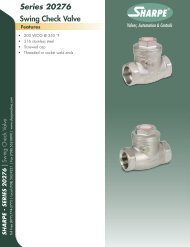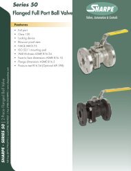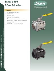
3-PIECE FULL PORT BALL VALVE â MODELS ... - Sharpe® Valves
3-PIECE FULL PORT BALL VALVE â MODELS ... - Sharpe® Valves
3-PIECE FULL PORT BALL VALVE â MODELS ... - Sharpe® Valves
- No tags were found...

You also want an ePaper? Increase the reach of your titles
YUMPU automatically turns print PDFs into web optimized ePapers that Google loves.
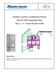
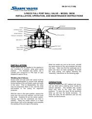
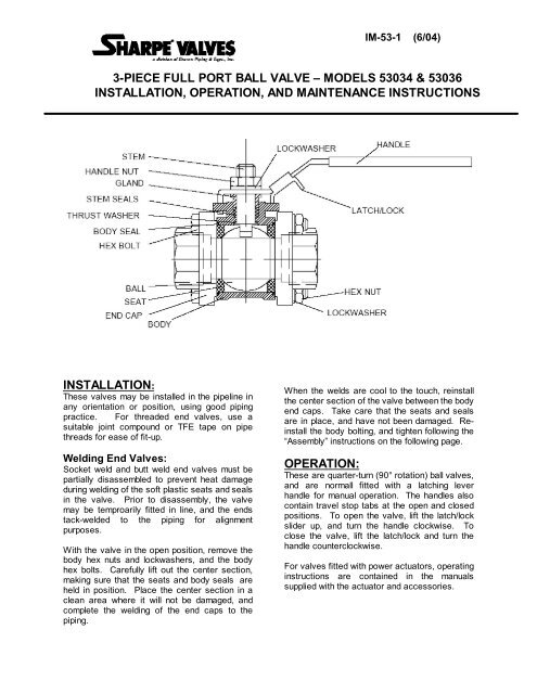
IM-53-1 (6/04)3-<strong>PIECE</strong> <strong>FULL</strong> <strong>PORT</strong> <strong>BALL</strong> <strong>VALVE</strong> – <strong>MODELS</strong> 53034 & 53036INSTALLATION, OPERATION, AND MAINTENANCE INSTRUCTIONSINSTALLATION:These valves may be installed in the pipeline inany orientation or position, using good pipingpractice. For threaded end valves, use asuitable joint compound or TFE tape on pipethreads for ease of fit-up.Welding End <strong>Valves</strong>:Socket weld and butt weld end valves must bepartially disassembled to prevent heat damageduring welding of the soft plastic seats and sealsin the valve. Prior to disassembly, the valvemay be temproarily fitted in line, and the endstack-welded to the piping for alignmentpurposes.With the valve in the open position, remove thebody hex nuts and lockwashers, and the bodyhex bolts. Carefully lift out the center section,making sure that the seats and body seals areheld in position. Place the center section in aclean area where it will not be damaged, andcomplete the welding of the end caps to thepiping.When the welds are cool to the touch, reinstallthe center section of the valve between the bodyend caps. Take care that the seats and sealsare in place, and have not been damaged. Reinstallthe body bolting, and tighten following the“Assembly” instructions on the following page.OPERATION:These are quarter-turn (90° rotation) ball valves,and are normall fitted with a latching leverhandle for manual operation. The handles alsocontain travel stop tabs at the open and closedpositions. To open the valve, lift the latch/lockslider up, and turn the handle clockwise. Toclose the valve, lift the latch/lock and turn thehandle counterclockwise.For valves fitted with power actuators, operatinginstructions are contained in the manualssupplied with the actuator and accessories.
MAINTENANCE:----WARNING----Do not attempt to performmaintenance on valves inpressurized lines.Stem Seal Adjustment:If leakage is evident from the stem packing area,tighten the packing gland (below the handle) 1/8turn. If the leakage persists, repeat tightening.If leakage cannot be corrected by tightening thegland, replacement of the stem seals will benecessary.Seal Replacement:Turn valve to the open position and removehandle nut, lockwasher, and handle. Loosenand remove packing gland from valve body.Loosen and remove body bolts, and removebody center section assembly, placing it on asuitable work surface. Remove seats and bodyseals.Using the handle if necessary, turn ball to theclosed position, and remove ball from body witha rolling motion away from the stem. Handleball with care to avoid damaging the surface.Push downwards on the top of the stem to slideit through the stem seals, and remove stem frominside body bore. Remove thrust washer fromstem, or from body bore if retained in body.Remove stem seals using a packing hook orsharp object.Sharpe recommends that all soft parts, includingseats be replaced with new parts, which can beordered in kit form.REASSEMBLY:Make sure all valve components are clean andundamaged before assembly.Install thrust washer on stem, and slide down toshoulder. Insert stem into body and upwardsthrough the stem bore until the shoulder isseated in the bore.Slide stem seal over stem top, and into stembore in body. Take care not to damage seal onstem threads. Install packing gland, and tightenfinger tight.Place stem in the “closed” position, and installthe ball carefully by rolling the stem tang into theball slot.Install seats in the body at both ends, makingsure the concave face fits against the ball, andpress the body seals into the grooves in thebody faces.Turn ball to the “open” position, and replacebetween the end caps in line. Slide body hexbolts through end caps and body guide holes,and secure with lockwashers and hex nuts.Tighten snugly.Tighten packing gland to the torque value givn inthe table below, and replace the handle,lockwasher, and handle nut.Tighten the body bolting to the torque valuesgiven in the table below, using a cross or starpattern to tighten evenly.Table 1 – Assembly TorquesValve SizeGlandTorque(in-lb)Body BoltTorque (inlb)¼” – 3/8” 35 50½” 35 110¾” – 1” 80 1151-1/4” – 115 1201-1/2”2” 115 1252-1/2” 250 3503” – 4” 350 4601260 Garnet Drive, Northlake, Illinois 60164-1028 Phone (630) 883-8020 Fax: (630) 833-2661 www.sharpevalves.com