ncr/doc/Kiosks/TechnicalManuals/7401_Kiosk_Sit... - Alsys Data
ncr/doc/Kiosks/TechnicalManuals/7401_Kiosk_Sit... - Alsys Data
ncr/doc/Kiosks/TechnicalManuals/7401_Kiosk_Sit... - Alsys Data

You also want an ePaper? Increase the reach of your titles
YUMPU automatically turns print PDFs into web optimized ePapers that Google loves.
N CRNCR EasyPoint <strong>7401</strong>Release 2.5<strong>Sit</strong>e Preparation Guide19797B005-0000-1255Issue D
The products described in this book are licensed products of NCR Corporation.NCR is a registered trademark of NCR Corporation.NCR EasyPoint and RealPOS are registered trademarks of NCR Corporation in the United States and/orother countries.Pentium and Celeron are registered trademarks of Intel Corporation.It is the policy of NCR Corporation (NCR) to improve products as new technology, components, software,and firmware become available. NCR, therefore, reserves the right to change specifications without priornotice.All features, functions, and operations described herein may not be marketed by NCR in all parts of theworld. In some instances, photographs are of equipment prototypes. Therefore, before using this <strong>doc</strong>ument,consult with your NCR representative or NCR office for information that is applicable and current.To maintain the quality of our publications, we need your comments on the accuracy, clarity, organization,and value of this book.Address correspondence to:Manager, Information ProductsNCR Corporation2651 Satellite Blvd.Duluth, GA 30096Copyright © 2002By NCR CorporationDayton, Ohio U.S.A.All Rights Reserved
<strong>Sit</strong>e PreparationiPrefaceSafety RequirementsThis is a contractual <strong>doc</strong>ument. It contains important warnings andconfers important legal rights and obligations. You are advised to readit carefully.It is the responsibility of the customer to assure that all installationpreparations are complete and in compliance with NCR specificationsand requirements and all applicable national, state, or local codes,regulations, and laws.ServicingCaution: This product does not contain user serviceable parts.Servicing should only be performed by a qualified service technician.Fuse ReplacementCaution: For continued protection against risk of fire, replace onlywith the same type and ratings of fuse.Attention: Pour prévenir et vous protéger contre un risque de feu,remplacer la fusible avec une autre fusible de même type, seulement.Power Supply Cord Used as Disconnect MeansCaution: The power supply cord is used as the main disconnectdevice. Ensure that the socket outlet is located/installed near theequipment and is easily accessible.Attention: Le cordon d'alimentation est utilisé comme interrupteurgénéral. La prise de courant doit être située ou installée å proximité dumatériel et être facile d'accés.Lithium Battery WarningCaution: Danger of explosion if battery is incorrectly replaced.Replace only with the same or equivalent type as recommended by themanufacturer. Discard used batteries according to the manufacturer'sinstructions.
ii<strong>Sit</strong>e PreparationAttention: Il y a danger d'explosion s'il y a remplacement incorrect dela batterie. Remplacer uniquement avec une batterie du même type oud'un type recommandé par le constructeur. Mettre au rébut lesbatteries usagées conformément aux instructions du fabricant.Battery Disposal (Switzerland)Refer to Annex 4.10 of SR814.013 for battery disposal.IT Power SystemThis product is suitable for connection to an IT power system with aphase-to-phase voltage not exceeding 240 V.Peripheral UsageThis terminal should only be used with peripheral devices that arecertified by the appropriate safety agency for the country of installation(UL, CSA, TUV, VDE) or those which are recommended by NCRCorporation.Caution: DO NOT connect or disconnect a printer, keyboard, or anyother terminal-powered peripheral while the terminal is powered on.Doing so may result in peripheral or system damage.System Weight ConsiderationsWarning: The NCR <strong>7401</strong>-1xxx and <strong>7401</strong>-2xxx terminals must bemounted securely to prevent a hazard. They must be installed inaccordance with local building codes. The post or wall on which theunit is mounted should be able to withstand four times the weight ofthe unit, which is approximately 20 lbs. (9 kg). The NCR <strong>7401</strong>-4xxx isa desk-top unit that has an assembled weight of approximately 90lbs. (40.8 kg).Environmental ConsciousnessNCR is demonstrating its concern for the environment by designing anintelligent power management system into this terminal that operatesefficiently whether the system is in a stand-alone or networkenvironment.
<strong>Sit</strong>e PreparationiiiAbout this BookGrounding InstructionsIn the event of a malfunction or breakdown, grounding provides apath of least resistance for electric current to reduce the risk of electricshock. This product is equipped with an electric cord having anequipment-grounding conductor and a grounding plug. The plug mustbe plugged into a matching outlet that is properly installed andgrounded in accordance with all local codes and ordinances. Do notmodify the plug provided – if it will not fit the outlet, have the properoutlet installed by a qualified electrician. Improper connection of theequipment-grounding conductor can result in a risk of electric shock.The conductor with insulation having an outer surface that is greenwith or without yellow stripes is the equipment-grounding conductor.If repair or replacement of the electric cord or plug is necessary, do notconnect the equipment-grounding conductor to a live terminal. Checkwith a qualified electrician or service personnel if the groundinginstructions are not completely understood, or if you are in doubt as towhether the product is properly grounded.Use only 3-wire extension cords that have 3-prong grounding plugsand 3-pole receptacles that accept the product’s plug. Repair or replacedamaged or worn cords immediately.This book provides site preparation information for terminalcomponents. Peripheral component and AC wiring site preparationinformation is NOT provided in this book. The associated reference<strong>doc</strong>uments are listed in the “Related <strong>Sit</strong>e Preparation <strong>Data</strong>” section.This book contains the information necessary for the preparation of asite that conforms to NCR specifications. It is very important that thesite complies with the requirements specified in the <strong>doc</strong>ument because,once the equipment has been installed, deficiencies in site preparationor the problems caused by these deficiencies are much more difficult todetect and correct. Further, failure to comply with these requirementsor to take proper steps to protect equipment against risks identified inthis <strong>doc</strong>ument may cause serious damage to the equipment and to thecustomer’s business.
iv<strong>Sit</strong>e PreparationIn addition to the need to comply with the requirements specified,electrical wiring and mechanical systems must also comply with allrelevant codes, laws, and regulations.It is important that a customer or his agent who is fully conversantwith the special requirements of electronic equipment prepare the site.The responsibility of ensuring that the site is prepared in compliancewith this <strong>doc</strong>ument remains with the customer.For information and guidance purposes only, a list is provided, ingeneral terms, of those matters for which the customer is responsible.This list is not intended to be comprehensive, and in no way modifies,alters, or limits the responsibility of the customer for all aspects ofadequate site preparation.NCR staff will be available to answer questions relating to the contentsof this <strong>doc</strong>ument except where:• A customer has been notified that a full or partial consultant serviceis available and/or that NCR will be willing to undertake apreliminary or final site survey and• The customer shall have entered into a formal contract with NCRfor provision of the same.No comment, suggestion, or advice offered or not offered aboutpreparation of the site, nor any inspection of the site, whether before ofafter preparation, is to be taken as approval of the location of the siteand equipment or its preparation. NCR will not be liable in respect toany comment, suggestion, or advice given by its staff or in respect toany failure to give advice.Finally, only the customer can know the full extent of damage that maybe caused to his business by reason of failure of the equipment which isto be installed. For this reason, it is the customer’s responsibility toascertain the extent of any possible damage to his existing or plannedbusiness, and to effect full insurance for all eventualities.
<strong>Sit</strong>e PreparationvReferences• NCR EasyPoint <strong>7401</strong> Hardware User’s Guide(B005-0000-1254)• NCR EasyPoint <strong>7401</strong> Hardware Service Guide(B005-0000-1341)• NCR EasyPoint <strong>7401</strong> Interface Guide(B005-0000-1405)• NCR EasyPoint <strong>7401</strong>/7454 Retail Terminal Parts Identification Manual(B005-0000-1072)
vi<strong>Sit</strong>e Preparation
<strong>Sit</strong>e PreparationviiTable of ContentsIntroduction 1<strong>7401</strong>-2xxx and 3xxx Models............................................ 1<strong>7401</strong>-4xxx Model.............................................................. 2Interpreting the Model Number..................................... 3Related <strong>Sit</strong>e Preparation <strong>Data</strong>......................................... 4Accessing Information Products .................................... 4Customer Responsibilities 5AC Store Wiring Requirements 6LAN Communications 6<strong>7401</strong>-2xxx and 3xxx System Configuration Diagram 7<strong>7401</strong>-4xxx System Configuration Diagram 8<strong>7401</strong>-2xxx and 3xxx Kit Configuration Diagram 9Physical Considerations 10Operating and Service Clearance Requirements......... 11Component Dimensions ............................................... 12<strong>7401</strong>-32xx Fixed Angle Mount (12.1-Inch)............. 12<strong>7401</strong>-35xx Fixed Angle Mount (15-Inch)................ 12<strong>7401</strong>-22xx/26xx Tilt Mount (12.1 Inch).................. 13<strong>7401</strong>-25xx/26xx Tilt Mount (15-Inch) .................... 13<strong>7401</strong>-22xx/26xx (12.1-Inch)..................................... 14<strong>7401</strong>-25xx/26xx (15-Inch) ....................................... 15<strong>7401</strong>-4xxx w/Keyboard and Pin Pad..................... 16
viii<strong>Sit</strong>e Preparation<strong>7401</strong>-4xxx w/Keyboard Only................................. 16<strong>7401</strong>-K540 (12.1 Inch) w/Keyboard Option .......... 17<strong>7401</strong>-K543 Wall Mount Bracket w/WideKeyboard Shelf ........................................................ 17<strong>7401</strong>-K580/590 w/Self-Service Printer (12.1Inch).......................................................................... 18<strong>7401</strong>-K580/590 w/Self-Service Printer (15-Inch).. 19<strong>7401</strong> with 7949 Pedestal Mount.............................. 20<strong>7401</strong> with 2336-K052 Pedestal Mount.................... 21<strong>7401</strong> 2336-K037 Pedestal Mount with KeyboardShelf.......................................................................... 22EasyPoint 45 Pedestal 2336-K045........................... 23<strong>7401</strong>-4xxx with EasyPoint 45 Pedestal 2336-K045.......................................................................... 24NCR 2189 Cash Drawer.......................................... 257158 Thermal Receipt/Impact Printer ................... 257167 Thermal Receipt and Impact Slip Printer ..... 267194 Thermal Receipt Printer ................................. 267196 Thermal Receipt Printer ................................. 277197 Thermal Receipt Printer ................................. 272336-K007 External CD-ROM Drive ...................... 282336-K008 USB RS-232 Port Server ........................ 28Component Weights ..................................................... 29Ventilation Clearance.................................................... 30NCR <strong>7401</strong> ................................................................. 30<strong>7401</strong> Power Requirements ............................................ 31Maximum Input Power Specifications .................. 31Typical Power Requirements (<strong>7401</strong>-2xxx and<strong>7401</strong>-3xxx) ................................................................ 31Typical Power Requirements (<strong>7401</strong>-4xxx) ............. 32Power Consumption Matrix ......................................... 33
<strong>Sit</strong>e PreparationixCable Routing Considerations 35<strong>7401</strong>-2xxx and 3xxx........................................................ 35Table-Top Mount .................................................... 36<strong>7401</strong>-4xxx........................................................................ 37<strong>7401</strong>-2xxx and 3xxx Mounting Considerations 38Viewing Height ............................................................. 38Terminal with K521 Wall Mount.................................. 39Terminal with K521 Wall Mount and K530 PoleStraps.............................................................................. 41Terminal with Printer and K525 Wall Bracket ............ 42Printer Only Mount (K523 Wall Bracket) .................... 45Terminal Only (K522 Universal Bracket)..................... 46Considerations for Enclosed Installations ................... 47Ventilation Clearances ............................................ 47Thermal Test Points ................................................ 48Service Access.......................................................... 4812.1-inch LCD No-Cabinet Feature <strong>7401</strong>-F752 ............ 49Installation Guidelines............................................ 50Mounting Specification Illustrations ..................... 5115-inch LCD No-Cabinet Feature <strong>7401</strong>-F757 ............... 52Installation Guidelines............................................ 52Mounting Specification Illustrations ..................... 53K/F 502 Flush Wall Mount........................................... 55Power Supply .......................................................... 56Wall Mount the Terminal Bracket.......................... 56<strong>7401</strong>-4xxx Mounting Considerations 57Viewing Height ............................................................. 57<strong>7401</strong>-4xxx Table Top Mount ......................................... 58<strong>7401</strong>-4xxx EasyPoint 45 Pedestal Floor Mount............ 59Mounting <strong>7401</strong>-4xxx Signage........................................ 60
x<strong>Sit</strong>e PreparationSystem Cables 61Cable Illustrations ......................................................... 63Dual Cash Drawer, Y-cable .................................... 63Ethernet, 10/100 Base-T.......................................... 63USB........................................................................... 64External CD-ROM Cable ........................................ 64External Parallel Cable............................................ 65Power, AC................................................................ 65Environmental Requirements 66Barometric Pressure ...................................................... 66Temperature .................................................................. 66Humidity........................................................................ 66AC Power Line Transient Protection 1<strong>Data</strong> Line Transient Protection....................................... 2
<strong>Sit</strong>e PreparationxiRevision RecordIssue Date RemarksA Aug. 00 First issueB Oct. 01 Update model and kit changesC May 02 Updated to Release 2.4.Add EasyPoint <strong>7401</strong>-45xx terminalC Jul 02 Add EasyPoint 45 PedestalD Dec 02 Updated to Release 2.5Added <strong>7401</strong>-26xx and <strong>7401</strong>-46xx modelsChanged <strong>7401</strong>-45xx references to <strong>7401</strong>-4xxx
xii<strong>Sit</strong>e PreparationRadio Frequency Interference StatementsFederal Communications Commission (FCC)Information to UserThis equipment has been tested and found to comply with the limits for a Class Adigital device, pursuant to Part 15 of FCC Rules. These limits are designed to providereasonable protection against harmful interference when the equipment is operated ina commercial environment. This equipment generates, uses, and can radiate radiofrequency energy and, if not installed and used in accordance with the instructionmanual, may cause harmful interference to radio communications. Operation of thisequipment in a residential area is likely to cause interference in which case the userwill be required to correct the interference at his own expense.NCR is not responsible for any radio or television interference caused by unauthorizedmodification of this equipment or the substitution or attachment of connecting cablesand equipment other than those specified by NCR. The correction of interferencecaused by such unauthorized modification, substitution or attachment will be theresponsibility of the user. The user is cautioned that changes or modifications notexpressly approved by NCR may void the user's authority to operate the equipment.Canadian Department of CommunicationsThis Class A digital apparatus complies with Canadian ICES-003.This digital apparatus does not exceed the Class A limits for radio noise emissionsfrom digital apparatus set out in the Radio Interference Regulations of the CanadianDepartment of Communications.Cet appareil numérique de la classe A est conforme à la norme NMB-003 du Canada.Le présent appareil numérique n'émet pas de bruits radioélectriques dépassant leslimites applicables aux appareils numériques de la classe A prescrites dans lerèglement sur le brouillage radioélectriques édicté par le ministrère desCommunications du Canada.Voluntary Control Council for Interference (VCCI)
<strong>Sit</strong>e PreparationxiiiInternational Radio Frequency Interference StatementWarning: This is a Class A product. In a domestic environment this product maycause radio interference in which case the user may be required to take adequatemeasures.
xiv<strong>Sit</strong>e PreparationIEC & EN Laser Product LabelCAUTION: Laserradiation whenopen and interlockdefeated.DO NOT STAREINTO BEAM.This laser moduledoes not complywith 21CFR1040.USE ONLY AS AComponent.(Label is attached to lasermodule inside the cabinet.)Class IIa Laser Product.Avoid Long-term Viewingof Direct Laser Light.Appareil à Laser de classe IIaEviter Toute Exposition Prolongèede la vue à la lumiè re laser directe.Class IIa Producto Laser. TratèDe no ver directamente èl RayoLaser por mucho tiempò.Laser PowerIEC & EN 60825-1 CLASS 1 LASER PRODUCTThe NCR EasyPoint <strong>7401</strong> scanner meets the following laser/LEDpower requirements.• Class IIa CDRH (Center for Devices and Radiological Health)• Class IIa Laser Product—Avoid long-term viewing of direct laserlight.• Class 1 EN60-825 (Europäische Norm)Following is the radiant energy of the laser/LED light as applied toeach of the specified requirements.Accessible Emission Limit (CDRH Calculation)Accessible Emission Limit EN60 825-1:1994+AII:1996173250.99 Milliwatts0.81 MilliwattsCaution: Use of controls or adjustments or performance of proceduresother than specified herein may result in hazardous radiationexposure.
<strong>Sit</strong>e PreparationxvDeclaration of ConformityManufacturer's NameManufacturer's AddressType of EquipmentModel NumberElectrical Ratings (Input)NCR CorporationNCR CorporationRetail Solutions Division – Atlanta2651 Satellite BoulevardDuluth, GA 30096-5810Information Technology EquipmentClass <strong>7401</strong>-2xxx and <strong>7401</strong>-3xxx100-120 V/200-240 V, 2.0 A/1.0 A, 50-60 HzNCR Corporation, 1700 South Patterson Boulevard, Dayton, OH 45459,USA, declares that the equipment specified above conforms to thereferenced EU Directives and Harmonized Standards.EU DirectiveHarmonized Standard(s)89/336/EEC (EMC) EN 55022EN 55024EN61003-2EN61003-373/23/EEC (Low Voltage) EN 60 950: A1 + A2 + A3 + A4 + AllNCR CorporationRetail Solutions Division — Atlanta2651 Satellite BoulevardDuluth, GA 30096-5810European Contact:International IP Counsel206 Marylebone RoadLondon, NW1 6LY, England
xvi<strong>Sit</strong>e PreparationDeclaration of ConformityManufacturer’s NameManufacturer’s AddressType of EquipmentModel NumberElectrical Ratings (Input)NCR CorporationNCR CorporationRetail Solutions Division – Atlanta2651 Satellite BoulevardDuluth, GA 30096-5810Information Technology EquipmentClass <strong>7401</strong>-4xxx100 - 240 V, 5.0 A, 50-60 HzNCR Corporation, 1700 South Patterson Boulevard, Dayton, OH 45459,USA, declares that the equipment specified above conforms to thereferenced EU Directives and Harmonized Standards.EU DirectiveHarmonized Standard(s)89/336/EEC (EMC) EN 55022EN 55024EN61003-2EN61003-373/23/EEC (Low Voltage)EN 60 950: A1 + A2 + A3 + A4 + AllNCR CorporationRetail Solutions Division — Atlanta2651 Satellite BoulevardDuluth, GA 30096-5810European Contact:International IP Counsel206 Marylebone RoadLondon, NW1 6LY, England
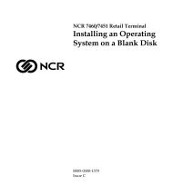
<strong>Sit</strong>e PreparationIntroduction<strong>7401</strong>-2xxx and 3xxx ModelsThis <strong>doc</strong>ument provides the information necessary to prepare a site toNCR specifications prior to installing a <strong>7401</strong> terminal. The site must beproperly prepared before the terminal is installed because sitepreparation deficiencies may be difficult to detect and correct afterinstallation.The <strong>7401</strong>-2xxx and <strong>7401</strong>-3xxx models are housed in an integrated,compact cabinet and can be tilt mounted or fixed-angle mounted.These models consists of separate pieces that may be combined in avariety of configurations. Certain combinations are mutually exclusive.You must determine the equipment that will actually be installedbefore proceeding with the site preparation.NCR<strong>7401</strong> -Tilt Mount<strong>7401</strong> -Fixed Angle Mount18049
2 <strong>Sit</strong>e Preparation<strong>7401</strong>-4xxx Model19889d
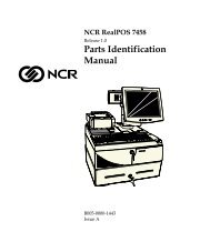
<strong>Sit</strong>e Preparation 3Interpreting the Model NumberNCR Model <strong>7401</strong> X X 1 X 8001Language01 = International EnglishPower Required80 = 110 -240 VAC 50/60 HzTouchscreen Type2 = Capacitive8 = Resistive1 = Self ServiceProcessor/LCD1 = Pentium2 = Summa PIII/Celeron 12.1"5 = Summa PIII/Celeron 15"6 = Summa II PIII/Celeron 15"Model2 = Standard3 = Scanner4 = Keylock Cabinet9 = No Cabinet19760
4 <strong>Sit</strong>e PreparationRelated <strong>Sit</strong>e Preparation <strong>Data</strong>AC Power and Communications WiringTitleNCR Ethernet Communications Wiring GuideNCR Terminal AC Power Wiring GuidelinesOrder NumberBST0-2118-82BST0-2115-53PeripheralsTitleNCR 7158 Thermal Receipt/Impact PrinterNCR 7166 Thermal Receipt/Impact PrinterNCR RealPOS 7167 Two-Station POS Printer Owner’sManualNCR 7194 Thermal Receipt Printer Owner’s GuideNCR 7196 Thermal Receipt PrinterNCR RealPOS 7197 Receipt Printer Owner’s ManualNCR <strong>7401</strong>-K580 Self-Service Printer Owner’s Guide(Discontinued)NCR <strong>7401</strong>-K590 Self-Service Printer Owner’s GuideOrder NumberB005-0000-1112B005-0000-1002B005-0000-1406B005-0000-1094B005-0000-1170B005-0000-1409B005-0000-1139B005-0000-1346Accessing Information ProductsElectronic versions (PDF format) are available on the Web at thefollowing locations:• http://inforetail.AtlantaGA.NCR.COM (NCR only)• http://www.info.NCR.COM (Anyone)
<strong>Sit</strong>e Preparation 5Customer ResponsibilitiesBefore the system can be installed, the customer must do or provide thefollowing:• When required by NCR, provide the NCR Customer Servicesrepresentative with appropriate drawings that indicate:− Location of the equipment−−<strong>Sit</strong>e wiring (power and communications, paths and lengths)Location of other equipment that may generate electrical noise,electromagnetic interference, or heat.• Make building alterations necessary to meet wiring and other siterequirements• Provide and install all communications cables, wall jacks, specialconnectors, and associated hardware• Provide and install necessary power distribution boxes, conduits,grounds, lightning protection devices, and associated hardware• Make sure all applicable codes, regulations, and laws (including,but not limited to, electrical, building, safety, and health) are met• Provide and install auxiliary power or other equipment as required• Provide storage or service areas as required• Meet all system/unit environmental requirements• Provide and install floor coverings and environmental systems thatlimit or control static electricity build-up and dischargeIn general, keep the NCR equipment area free from dust, smoke, lint,and other particles. Restrict smoking, eating, and drinking around theequipment. Avoid locating the equipment near other machines thatgenerate ink, carbon, and paper dust particles.Finally, only the customer can know the full extent of the damage thatmay be caused to his business by reason of failure of the equipmentthat is to be installed. For this reason, it is the customer's responsibilityto ascertain the extent of any such possible damage to his existing orplanned business, and to effect full insurance for all eventualities.
6 <strong>Sit</strong>e PreparationAC Store Wiring RequirementsThe customer must provide suitable AC power for the <strong>7401</strong> terminals,associated equipment, and devices. A dedicated, unswitched powerline to the NCR equipment installation is recommended. Refer to theWorkstation and Peripherals AC Wiring Guide (BSTO-2115-53) for storeAC wiring requirements. The AC outlet must be installed near theterminal and easily accessible to the operator.LAN CommunicationsThe terminal supports Ethernet 10/100Base-T local area network(LAN) communication protocol. For Ethernet communications wiringspecifications, refer to the NCR Ethernet Wiring Guide (BST0-2118-82).
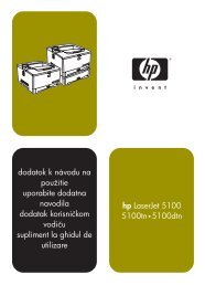
<strong>Sit</strong>e Preparation 7<strong>7401</strong>-2xxx and 3xxx System Configuration Diagram71677197719471967158<strong>7401</strong>Keyboard<strong>7401</strong>-K580789278377890 RS232 PS/2 KBD2336-K008 (RS232/1OptionallyPowered)USBProcessorBoardVGAPCMCIA(Wireless)7167 7197MicrophonePOS ConnectorBoardParallelCash DwrAudioSVideoEthernet<strong>7401</strong>-K5902336-K007218919296a
8 <strong>Sit</strong>e Preparation<strong>7401</strong>-4xxx System Configuration DiagramFull PagePrinterPowerSupplyPowerLANParallelSpeakerSpeakersIRDAIRDAReceiverProcessor BoardMSRSwipeMSRS-Video(Powered)COM1USB 1USB 2RS-232 Ports(Powered)COM2 COM3 COM4USBCamera(Kit)TrackballPin PadMotorizedCardReaderPowerSupply19794b
<strong>Sit</strong>e Preparation 9<strong>7401</strong>-2xxx and 3xxx Kit Configuration Diagram<strong>7401</strong> w/K590<strong>7401</strong>-3xxx<strong>7401</strong>-2xxx2336-K0372336-K052F501K542F502K533F/K059F511F512F521F101F504F505F201F200K540K536K543K530K535K523F/K590K525K53418318d-P
10 <strong>Sit</strong>e PreparationPhysical ConsiderationsThis section presents the following <strong>7401</strong> information:• Operating and service clearance requirements• Display mounting considerations• <strong>7401</strong> and component dimensions• Component weights• Airflow requirements• Power requirements
<strong>Sit</strong>e Preparation 11Operating and Service Clearance RequirementsLocation Component Distance ReasonAbove 7194 Printer 228 mm (9 in.) Clearance to raise printer cover7196 Printer 254 mm (10 in) Clearance to raise printer cover7197 Printer 267 mm (10.5 in.) Clearance to raise printer cover7158 Printer 305 mm (12 in.) Clearance to raise printer cover7167 Printer 305 mm (12 in.) Clearance to raise printer coverCRT Displays 50 mm (2 in.) Clearance for CRT tiltAll units 153 mm (6 in.) Service clearanceLeft Side 7167 Printer 305 mm (12 in.) Clearance slip insertionAll units 153 mm (6 in.) Service clearanceRight Side CRT Display 64 mm (2.5 in.) Clearance for CRT rotation5972 2 x 20 Display 25 mm (1 in.) Clearance for display rotationAll units 202 mm (8 in.) Service clearanceFront 7156 Printer 40 mm (1.5in.) Clearance to open printer door<strong>7401</strong>-K580/K590Printer255 mm (10 in.) Clearance to open printer paperrolls.Drawer unit 330 mm (13 in.) Clearance to open drawerBehind CRT Displays 64 mm (2.5 in.) Clearance for CRT tiltAll units 153 mm (6 in.) Service clearance
12 <strong>Sit</strong>e PreparationComponent Dimensions<strong>7401</strong>-32xx Fixed Angle Mount (12.1-Inch)400 mm(16 in.)370 mm(14.5 in.)280 mm(11 in.)450 mm(17.6 in.)400 mm(16 in.)120 mm(4.75 in.)16420<strong>7401</strong>-35xx Fixed Angle Mount (15-Inch)426 mm(16.75 in.)391 mm(15.38 in.)331 mm(13 in.)460 mm(18.1 in.)420 mm(16.5 in.)135 mm(5.25 in.)18139
<strong>Sit</strong>e Preparation 13<strong>7401</strong>-22xx/26xx Tilt Mount (12.1 Inch)400 mm(16 in.)370 mm(14.5 in.)380 mm(15.0 in.)360 mm(14.0 in.)15970<strong>7401</strong>-25xx/26xx Tilt Mount (15-Inch)425 mm(16.75 in.)394 mm(15.5 in.)412 mm(16.25 in.)35 mm(14.0 in.)18134
14 <strong>Sit</strong>e Preparation<strong>7401</strong>-22xx/26xx (12.1-Inch)401mm(15.8 in.) 40.5 mm(1.6 in)370 mm(14.5 in.)381 mm(15.0 in.)312 mm(12.3 in.)53.4 mm(2.1 in)18200
<strong>Sit</strong>e Preparation 15<strong>7401</strong>-25xx/26xx (15-Inch)426 mm(16.8 in.)391 mm(15.5 in.)14.3 mm(0.6 in.)338 mm(13.3 in.)392.1 mm(15.4 in.)53.4 mm(2.1 in.)78.8 mm(3.1 in.)18201
16 <strong>Sit</strong>e Preparation<strong>7401</strong>-4xxx w/Keyboard and Pin Pad450.85 mm(17.75 in.)393.7 mm(15.5 in.)210 mm(8.27 in.)152 mm(5.98 in.)50 mm(1.97 in.)521 mm(20.5 in.)513 mm(20.2 in.)555.75 mm21.88 in.)90 mm(3.54 in.)620 mm(24.41 in.)23 mm(0.91 in.)125 mm(4.91 in.)565 mm(22.25 in.) 19761<strong>7401</strong>-4xxx w/Keyboard OnlyThe optional narrow Keyboard Tray for use with Keyboards that donot have a Pin Pad has a width of 394 mm (15.5 in.).
<strong>Sit</strong>e Preparation 17<strong>7401</strong>-K540 (12.1 Inch) w/Keyboard Option400 mm(16 in.)550 mm(21.5 in.)297 mm(11.63 in.)400 mm(16 in.)17296<strong>7401</strong>-K543 Wall Mount Bracket w/Wide Keyboard Shelf383 mm(15.06 in.)97 mm(7.38 in.)19900
18 <strong>Sit</strong>e Preparation<strong>7401</strong>-K580/590 w/Self-Service Printer (12.1 Inch)400 mm(16 in.)370 mm(14.5 in.)280 mm(11 in.)880 mm(34.5 in.)530 mm(21 in.)180 mm(7.0 in.)180 mm(7.0 in.)16698
<strong>Sit</strong>e Preparation 19<strong>7401</strong>-K580/590 w/Self-Service Printer (15-Inch)426 mm(16.75 in.)391 mm(15.5 in.)330 mm(13 in.)900 mm(35 in.)530 mm(21 in.)180 mm(7.0 in.)180 mm(7.0 in.)16698a
20 <strong>Sit</strong>e Preparation<strong>7401</strong> with 7949 Pedestal Mount400 mm(16 in.)Spacer<strong>7401</strong>-K580203 mm(8 in.)171 mm(6 3/4 in.)1372 mm(54 in.)203 mm(8 in.)457 mm(18 in.)457 mm(18 in.)192897949-K035 7949-K033
<strong>Sit</strong>e Preparation 21<strong>7401</strong> with 2336-K052 Pedestal MountOptional Spacer2336-K051198 mm(7.8 in.)175 mm(6.9 in.)1321 mm(52 in.)<strong>7401</strong>-K590203 mm(8 in.)597 mm(23.5 in.)597 mm(23.5 in.)19319
22 <strong>Sit</strong>e Preparation<strong>7401</strong> 2336-K037 Pedestal Mount with Keyboard ShelfOptional Spacer2336-K051198 mm(7.8 in.)175 mm(6.9 in.)1321 mm(52 in.)<strong>7401</strong>-K580/K590203 mm(8 in.)597 mm(23.5 in.)597 mm(23.5 in.)19320
<strong>Sit</strong>e Preparation 23EasyPoint 45 Pedestal 2336-K045375 mm(14.75 in.)336.5 mm(13.25 in.)914.5 mm(36 in.)660 mm(26 in.)614.7 mm(24.2 in.)20223
24 <strong>Sit</strong>e Preparation<strong>7401</strong>-4xxx with EasyPoint 45 Pedestal 2336-K0451435 mm(56.5 in.)915 mm(36 in.)660 mm(26 in.)614.7 mm(24.2 in.)20047
<strong>Sit</strong>e Preparation 25NCR 2189 Cash Drawer464 mm(18.25 in.)133 mm(5.25 in.)527 mm(20.5 in.)330 mmOperating and (13 in.)Service Clearancefor Drawer166767158 Thermal Receipt/Impact Printer165 mm(6.50 in.)305 mm(12.00 in.)336 mm(13.25 in)229 mm(9.00 in)17307
26 <strong>Sit</strong>e Preparation7167 Thermal Receipt and Impact Slip PrinterTop Cover Open296 mm(11.7 in.)174 mm(7.0 in.)262 mm(10.3 in.)190 mm(7.5 in.)316 mm(12.5 in.)19711b7194 Thermal Receipt Printer85 mm(3.30 in.)130 mm(5.10 in.)212 mm(8.3 in.)157 mm(6.20 in.)187 mm(7.4 in.)16492
<strong>Sit</strong>e Preparation 277196 Thermal Receipt Printer108 mm(4.25 in.)146 mm(5.75 in.)254 mm(10.00 in.)140 m(5.50 in.)173067197 Thermal Receipt PrinterTop Cover Open256 mm(10.1 in.)156 mm(6.25 in.)184 mm(7.25 in.)146 mm(7.75 in.)19712c
28 <strong>Sit</strong>e Preparation2336-K007 External CD-ROM Drive155 mm(6.1 in.)218 mm(8.6 in.)23 mm(0.9 in.)16951Note: Allow 75 mm (3 in.) clearance in the back of the NCR 2336-K007External CD-ROM Drive for connector and cable clearance.2336-K008 USB RS-232 Port Server183 mm(7.2 in.)111 mm(4.4 in.) 26 mm(1.0 in.)16950
<strong>Sit</strong>e Preparation 29Component WeightsThe following table shows the component weights for each integratedcomponent.<strong>7401</strong> Components Weightkg.lbs.<strong>7401</strong>-4xxx with paper roll and all components 40.8 90Full width thermal paper roll 2.75 7.38ATX 38 Thermal Printer 4.8 12.86Motorized Card Reader 0.5 1.35Keyboard with Pin Pad 3.04 8.15EasyPoint 45 Pedestal 22.68 50.04055 Uninterruptible Power Supply 4.53 10.0<strong>7401</strong>-3000 Fixed Angle Mount 9.6 21.5<strong>7401</strong>-3500 Fixed Angle Mount 10.9 24.0<strong>7401</strong>-2000 Tilt Mount 7.3 16.4<strong>7401</strong>-K580 9.6 21.5<strong>7401</strong>-K590 8.5 18.7Scanner Module 4.0 9.02189 Cash Drawer 10.3 22.75972-1000 Remote Customer Display 0.7 1.57158 Receipt/Impact Printer 4.8 10.57167 Thermal Receipt & Impact Slip Printer 4.5 107194 Thermal Receipt Printer 1.3 2.87197 Thermal Receipt Printer 1.53 3.42336-K037 Pedestal with Keyboard Shelf 22.68 502336-K052 Standard Pedestal 22.68 502336-K051 Spacer Assembly for 2336-K052 2.95 7.92336-K007 External CD-ROM Drive 0.6 1.32336-K008 USB RS-232 Port Server 0.3 0.6
30 <strong>Sit</strong>e PreparationTo obtain the total maximum weight of an integrated configuration,add the weights of the appropriate individual components. Thefollowing table provides an example.Terminal Component Weigh (kg) Weigh (lb)<strong>7401</strong>-35xx Terminal 10.88 24.0Keyboard .68 1.5<strong>7401</strong>-K590 Printer 8.48 18.72336-K037 Pedestal with Keyboard Shelf 22.68 50.04055 Uninterruptible Power Supply 4.53 10.0Total 47.25 104.2Miscellaneous items and shipping materials 5.22 11.5Shipping total 52.47 115.7Ventilation ClearanceLeave the minimum clearances shown below for proper coolingconditions for the <strong>7401</strong> terminal.NCR <strong>7401</strong>25 mm(1 in.)76 mm(3 in.)Minimum Horizontal ClearanceMinimum Vertical Clearance16423
<strong>Sit</strong>e Preparation 31<strong>7401</strong> Power RequirementsThe Core Module contains a three-wire, single-phase, selectable120/240 volt AC, 85 Watt power supply. The supply powers the <strong>7401</strong>,scanner, VFD display, keyboard, USB interface, cash drawer, integratedspeakers, and PCMCIA cards.The following tables show operating specifications for the powersupply.Maximum Input Power Specifications120 volt 240 voltVoltage Ranges 90 - 136 VAC 198 - 257 VACFrequency 50/60 Hz 50/60 HzCurrent (A) 2.5 1.25Power (W) 85 85Power Factor (typical) 0.48 0.38Typical Power Requirements (<strong>7401</strong>-2xxx and <strong>7401</strong>-3xxx)<strong>7401</strong> Configuration <strong>7401</strong> Condition Amps Watts*120 Volt12.1” LCD500 MHz PIII120 Volt15” LCD500 MHz PIIISoft OFF (Sleep Mode) 0.33 19Idle (Power On) 0.51 29.4Active, during scanning 0.55 31.7Soft OFF (Sleep Mode) 0.33 19Idle (Power On) 0.55 31.7Active, during scanning 0.60 34.6240 VoltSoft OFF (Sleep Mode) 0.17 1515” LCD500 MHz PIIIIdle (Power On) 0.28 25.5Active, during scanning 0.30 27.4* Adjusted by Power Factor
32 <strong>Sit</strong>e PreparationTypical Power Requirements (<strong>7401</strong>-4xxx)The following table shows power consumption for a <strong>7401</strong>-4512 withfull-page printer, motorized card reader, and Pin Pad.System <strong>7401</strong>-4512 Condition Amps Watts*120 Volt240 VoltAll peripherals powered and coremodule in Soft OFFSystem Idle at Windows Desktop(Power On)1.0 57.61.3 74.9Active during motorized card read 1.7 97.9Active during typical print 2.5 144Active maximum consumption 6.0 345.6All peripherals powered and coremodule in Soft OFFSystem Idle at Windows Desktop(Power On)0.5 45.60.65 59.3Active during motorized card read 0.85 77.5Active during typical print 1.25 114Active maximum consumption 3.0 273.6* Adjusted by Power Factor
<strong>Sit</strong>e Preparation 33Power Consumption MatrixThe following table is provided as a reference of the powerconsumption of the peripherals available on the <strong>7401</strong>.Note: All power data listed in the table below is rated in amperage.<strong>7401</strong> Power MatrixItem Description 3.3VDC 5.0VDC 12VDC Requires external power sourcePower Supply (85 Watts 497-0415503) 4.10 7.80 2.70Summa POS Motherboard with CPU, & up to 128MBMem1.00 1.50 0.08Personality Board – <strong>7401</strong> 0.20Safety – Contingency 0.20 0.50 0.30Current available for Peripherals/Options 2.90 5.60 2.32Peripherals (subtract from line above)LCDs: TFT or DSTN 0.29 0.80Integrated Display 4x20 VFD Powered from ParallelPort1.00Display 4x20 VFD Int'l, Powered from Parallel Port 2.005972 2x20 VFD Display Powered from Parallel Port 0.505972 2x20 VFD Display Powered from Serial Port 0.108MB or 32MB Disk on Chip 0.50PC Keyboard 0.20MSR ModulesTouch Screen feature 0.25Integrated speakers 0.33Hard Disk Drive 2.5" 0.50External CD-ROM Drive (Parallel) 1.00USB to 4 port RS-232 (2336-K008) 0.50USB to 2 port RS-232 (2336-K012) 0.50PCMCIA Controller 0.407837 Hand held Scanner Powered from Serial Port 0.30 1416-C430-0025
34 <strong>Sit</strong>e Preparation<strong>7401</strong> Power Matrix (continued)Item Description 3.3VDC 5.0VDC 12VDC Requires external power source7892 Presentation Scanner Powered from Serial Port 0.50 1416-C643-00305945 Electronic Payment Device (497-0411818) 0.50 1416-C634-40007194, 7158, 7196, Printers (always require brick) X5992 Signature capture device X5945 Electronic Payment Device X7892 Presentation Scanner X2336-K016 CCD Hand Held Scanner X2010 Coin Dispenser XMettler Toledo Scale ( 2336-K600)Ethernet to RS 232 Expander (2336-K001)XX
<strong>Sit</strong>e Preparation 35Cable Routing Considerations<strong>7401</strong>-2xxx and 3xxxExternal cables can be routed out the back or the bottom of the PedestalMount.16424
36 <strong>Sit</strong>e PreparationTable-Top MountThe internal cable connectors on the terminal are located on theunderside of the Core Module under the Cable Cover.Cable CoverThumb Screw15968
<strong>Sit</strong>e Preparation 37<strong>7401</strong>-4xxxExternal cables can be routed out the back or the bottom of theterminal. A 63.5 mm (2.5 in.) hole that aligns with the hole in the TableTop Mount must be cut in the table top when routing cables out thebottom of the terminal.19795
38 <strong>Sit</strong>e Preparation<strong>7401</strong>-2xxx and 3xxx Mounting ConsiderationsViewing HeightThe terminal should be mounted approximately 1.2 m (48 in.) from thefloor for proper use.1.2 m (48 in)RecommendedHeight from Floor16445
<strong>Sit</strong>e Preparation 39Terminal with K521 Wall Mount7 in.8.7 in.K5214 in.7.8 in.19291
40 <strong>Sit</strong>e PreparationLag Screws (4)Wall Bracket1.2 m (48 in)RecommendedHeight from Floor17715K521 Wall Mount
<strong>Sit</strong>e Preparation 41Terminal with K521 Wall Mount and K530 Pole Straps1.2 m (48 in)RecommendedHeight from FloorK521K530 Mounting Strap19283Note: K530 also includes pole mount adapter brackets used with K525.(See illustration on next page.)
42 <strong>Sit</strong>e PreparationTerminal with Printer and K525 Wall Bracket15.35 in.Mounting Screw(on both sides)33.70 in.K530 PoleBracket15.35 in.3.75 in.7.80 in.19282
<strong>Sit</strong>e Preparation 43Lag Screws (6)1.2 m (48 in)RecommendedHeight from FloorWall Bracket17593K525 Wall Mount
44 <strong>Sit</strong>e PreparationMounting Screw(on both sides)17735K525 with K530 Pole Mount Straps
<strong>Sit</strong>e Preparation 45Printer Only Mount (K523 Wall Bracket)Mounting Screw(on both sides)14.00 in.12.00 in.K5234 in.7.820 in.19294
46 <strong>Sit</strong>e PreparationTerminal Only (K522 Universal Bracket)The terminal can be mounted on a flat surface or pedestal using theUniversal Mounting Bracket.Flat Horizontal SurfaceMounting PlateK522Securing Screw19295
<strong>Sit</strong>e Preparation 47Considerations for Enclosed InstallationsTerminals that are mounted in an enclosure must meet certain thermaland environmental requirements as illustrated and noted in thefollowing pages.Ventilation ClearancesVerify that all clearance specifications are met as shown below.38 mm1.5 in.38 mm1.5 in.76 mm(3 in.)Door ShownOpen203 mm(8 in.)203 mm(8 in.)356 mm(14 in.)154 mm(6 in.)25 mm(1 in.)17315Note: The enclosure in this illustration is typical and is for clearancespecifications only.
48 <strong>Sit</strong>e PreparationThermal Test PointsWith the terminal installed in the enclosure, verify that the temperaturedoes not exceed 45 o C (115 o F) in the operating environment. Thermaltest points are shown below:Thermal Test Points(Both sides of terminal)17316Note: For terminal servicing information refer to NCR EasyPoint <strong>7401</strong>Hardware Service Guide (B005-0000-1341).Service AccessThe enclosure must provide access to certain locations for servicepurposes. The <strong>7401</strong> can be mounted as a stand-alone unit, with aprinter module attached, or terminal and printer mounted separately.
<strong>Sit</strong>e Preparation 4912.1-inch LCD No-Cabinet Feature<strong>7401</strong>-F752The 12.1-inch LCD No-Cabinet Feature (F752) is purchased bycustomers who design their own enclosures to meet their specificneeds. This section provides information that must be considered whendesigning enclosures.Front View18577Motion SensorBack View18743
50 <strong>Sit</strong>e PreparationInstallation Guidelines• To prevent moisture from entering system, the front of the displaymust be in close contact with the opening in the enclosure.• Within every custom enclosure, the Electronics Box Back CoverMUST remain installed because it helps dissipate the heatgenerated by the CPU.• Adequate ventilation must be provided in every custom enclosure.The maximum allowable ambient temperature within anyenclosure is 45 o C (113 o F).• To prevent accidental shorts, the power supply and any otherperipheral within the enclosure must be mounted securely andwithin reach of the display’s connectors.• This feature comes with a motion sensor that is at the end of a381 mm (15 in.) cable. When using the motion sensor, it must bemounted between 25 and 76 mm (1 to 3 in.) below the bottom of thedisplay and centered along the width of the display.• Compliance of this device with regulatory requirements must beverified in the end-use application.• This device is a component that requires a suitable enclosure in itsend-use application. The end-use product in which this componentis used should be certified in accordance with UL 1950, EN60950,IEC950 or other applicable safety standard.Caution: NCR displays are not designed for horizontal or inverteduse. NCR displays must be mounted no more than 40 o forward orbackward from horizontal. Failure to follow this guideline could resultin overheating.
<strong>Sit</strong>e Preparation 51Mounting Specification Illustrations12.59 mm(.496 in.)218.44 mm(8.6 in.)16 mm(.63 in.)299.72 mm(11.8 in.)Front surface of display bezel mustprotrude through enclosure to providesecure and watertight fit.NCR enclosure frontstypically use a dimension of302.26 mm (11.9 in.) +/-.254 mm (.01 in.) by221.23 mm (8.71 in.) +/-.254 mm (.01 in.) withradiuses in the corners of 2.54 mm (.1in.).Use four #8-32 machine screwsto mount display into enclosure.264.16 mm(10.4 in.)327.15 mm(12.88 in.)18576
52 <strong>Sit</strong>e Preparation15-inch LCD No-Cabinet Feature<strong>7401</strong>-F757The 15-inch LCD No-Cabinet Feature (F757) is purchased by customerswho design their own enclosures to meet their specific needs. Thissection provides information that must be considered when designingenclosures.Installation Guidelines• To prevent moisture from entering system, the front of the displaymust be in close contact with the opening in the enclosure.• Within every custom enclosure, the Electronics Box Back CoverMUST remain installed because it helps dissipate the heatgenerated by the CPU.• Adequate ventilation must be provided in every custom enclosure.The maximum allowable ambient temperature within anyenclosure is 45 o C (113 o F).• To prevent accidental shorts, the power supply and any otherperipheral within the enclosure must be mounted securely andwithin reach of the display’s connectors.• This feature comes with a motion sensor that is at the end of a381 mm (15 in.) cable. When using the motion sensor, it must bemounted between 25 and 76 mm (1 to 3 in.) below the bottom of thedisplay and centered along the width of the display.• Compliance of this device with regulatory requirements must beverified in the end-use application.• This device is a component which requires a suitable enclosure inits end-use application. The end-use product in which thiscomponent is used should be certified in accordance with UL 1950,EN60950, IEC950 or other applicable safety standard.Caution: NCR displays are not designed for horizontal or inverteduse. NCR displays must be mounted no more than 40 o forward orbackward from horizontal. Failure to follow this guideline could resultin overheating.
<strong>Sit</strong>e Preparation 53Mounting Specification IllustrationsThe following illustration shows the minimum allowable dimensionsfor the display opening when the optional cosmetic bezel is used.OPTIONAL COSMETIC BEZELGASKET MUST MEET INSIDE SURFACEOF CUSTOM DISPLAY OPENING.(OPTIONAL COSMETIC GASKET NOT USEDIF OPTIONAL BEZEL IS NOT USED).348.7 mm3.730 in. 4.2 mm.165 in.9.4 mm.372 in.270 mm10.630 in.FRONT SURFACE OF DISPLAY BEZEL (IF USED)MUST PROTRUDE THROUGH ENCLOSURE. GASKETMUST MEET INSIDE SURFACE OF CUSTOMAPPLICATION'S DISPLAY OPENING. THIS ISTO PROVIDE A SECURE AND WATERTIGHT FIT.USE 4 #8-32 MACHINE SCREWS INCORNERS OF UNIT TO MOUNT DISPLAYINTO ENCLOSURE. 8 TOTAL SCREWSMAY BE USED FOR MULTIPLE MOUNTINGCONFIGURATIONS.345.4 mm13.600 in.156.2 mm6.150 in.175 mm6.888 in.141.6 mm5.575 in.292.4 mm11.510 in.22.9 mm.900 in.200.7 mm7.900 in.17.2 mm.678 in.19100
54 <strong>Sit</strong>e PreparationThe following illustration shows the maximum allowable dimensionsfor the display opening when the optional cosmetic bezel is not used.Gasket must meet inside surface of customapplication's display opening. This is to providea secure and watertight fit.312.5 mm12.305 in. 13.7 mm0.540 in.27.5 mm1.083 in.235.6 mm9.275 in.Use four #8-32 machine screws in thecorners of the unit to mount the displayinto an enclosure. Six total screws maybe used for multiple mounting configurations.345.4 mm13.6 in.156.2 mm6.15 in.175 mm6.888 in.141.6 mm5.575 in.292.4 mm11.51 in.22.9 mm0.900 in.200.7 mm17.2 mm7.9 in.0.678 in.19101
<strong>Sit</strong>e Preparation 55K/F 502 Flush Wall MountThe Core Module (without either mount) can be mounted flush againsta wall. The following shows mounting configuration and brackets:Flush Mount w/Power SupplyMounted on the Outside WallFlush Mount w/Power SupplyMounted on the Inside Wall16683Note: Refer to the Cable Illustrations section for cable pass-through holesizes.
56 <strong>Sit</strong>e PreparationPower Supply152 mm(6 in.)102 mm(4 in.)57 mm(2.25 in.)17406Wall Mount the Terminal BracketDrill a hole in the wall for the cables if you are mounting the powersupply on the opposite side of the wall.Flush Mounting BracketWall PlateCable RoutingCable Routing(through wall)16684
<strong>Sit</strong>e Preparation 57<strong>7401</strong>-4xxx Mounting ConsiderationsViewing HeightThe terminal should be mounted approximately 88.9 cm (35 in.) fromthe floor for proper use. This provides for a keyboard height ofapproximately 94 cm (37 inches) for stand-up or wheel chair use and aviewing height to the center of the screen of 120 cm (48 in.).120 cm(48 in.)94 cm(37 in.)89 cm(35 in.)Floor19899
58 <strong>Sit</strong>e Preparation<strong>7401</strong>-4xxx Table Top MountThe terminal can be mounted on a flat surface using the Table TopMount (497-0424868). Mounting hole center to center measurementsare shown in the following illustration. When routing the cables out thebottom of the terminal, a 63.5 mm (2.5 in.) hole must be cut in the tabletop that aligns with the hole in the Table Top Mount.Note: This mount is also used to secure the <strong>7401</strong>-4xxx to the EasyPoint45 Pedestal 2336-K045.345 mm(13.58 in.)311.15 mm(12.25 in.)254 mm(10 in.)71.75 mm(2.82 in.)358 mm(13.93 in.)76.75 mm(3.02 in.)63.5 mm OD(2.5 in.)19891
<strong>Sit</strong>e Preparation 59<strong>7401</strong>-4xxx EasyPoint 45 Pedestal Floor MountThe EasyPoint 45 pedestal may be secured to the floor before mountingthe <strong>7401</strong>-4xxx terminal onto the pedestal. Two 12.7 mm (0.5 in.) holesare provided in the base of the pedestal. Use 11 mm or 12 mm (0.375 in.to 0.5 in.) bolts or lag screws to secure the pedestal to the floor.122.17 mm4.81 in.12.7 mm(0.5 in.)Holes20225
60 <strong>Sit</strong>e PreparationMounting <strong>7401</strong>-4xxx SignageThe Cabinet Back Panel has four (4) holes on each side that may beused to mount signage. Use 8-32 screws to mount the signage display.The length of the screw is determined by the thickness of the signagemount plus 6 mm (0.25 in.). Do not use a screw that extends inside thecabinet more than 6 mm (0.25 in.).35 mm(1.38 in.)26 mm(1.02 in.)17 mm(0.67 in.)8 mm(0.31 in.)9.17 mm(0.361 in.)101.6 mm(4 in.)101.6 mm(4 in.)101.6 mm(4 in.)33.5 mm(1.319 in.)1 2Label areas1 - 140 mm (5.5 in.) x 10 mm (0.375 in)2 - 76 mm (3 in.) x 12.5 mm (0.5 in.)19967bThe untextured areas above the paper chute (1) and above the cardreader (2) are used for signage logos.
<strong>Sit</strong>e Preparation 61System CablesCable Type Cable Name NCR Part No. Corp. ID No ApproximateCable LengthsCash Drawer Dual Drawer, Y cable 497-0409394 1416-C372-0006 0.6 m/2 ftCommunications Ethernet, 10/100Base-T 497-0008623 1416-C041-0030 3 m/10 ft(Unshielded)RS-232, Integrated 497-0407427 1416-C337-0010 1 m/3 ftInterfaceCable – RS-232, DB9’s 497-0421198 1416-C705-0018w/Secure LockingRS-232, Remote 497-0407429 1416-C337-0040 4 m/13 ftRS-232 Conversion Cable 497-0424853 1416-C759-0013 1.3 m/4.1 ft(Model 4000 Y-cable)USB 497-0415949 1416-C528-0010 1 m/3 ftUSB 497-0415950 1416-C528-0040 4 m/13 ftDisplays Parallel I/F Cable 497-0411000 1416-C472-0006 0.6 m/2 ft(adapter cable)Power U.S. – Straight 006-1009037 3 m/10 ftU.S. – Twist-lock 250-0023191 1416-C419-0030 3 m/10 ftIntl. – straight ‘bm’ power 006-8601010 1416-C323-0030 3 m/10 ftSEV – straight ‘bm’ power 006-8601011 1416-C408-0030 3 m/10 ftUK – straight ‘bm’ power 006-8601012 1416-C409-0030 3 m/10 ftAustralia – straight ‘bm’ 006-8601019 1416-C410-0030 3 m/10 ftpowerJapan – Power Cord (US 006-8604879 1416-C608-0030 3 m/10 ft.Style with T-Mark)Japan – Twist-lock,straight ‘bm’ power006-8601001 1416-C393-0030 3 m/10 ftPrinter Interface 7194/7158 Printer 497-0408349 1416-C359-0007 0.7 m/2 ft.497-0407943 1401-C266-0040 4 m/13 ft497-0409379 1416-C266-0152 15.2 m/50 ft
62 <strong>Sit</strong>e PreparationCable Type Cable Name NCR Part No. Corp. ID No ApproximateCable LengthsPrinter ExtenderDrop Cables(7453-K641)7166/7196 Printer/<strong>7401</strong>terminal497-0411815 1416-C417-0040 4 m/13 ft7194 Printer 497-0411816 1416-C417-0040 4 m/13 ft497-0405945 1416-C286-0040 4 m/13 ft7194 Printer 497-0411923
<strong>Sit</strong>e Preparation 63Cable IllustrationsDual Cash Drawer, Y-cable497-0409394CashDWR. #1CashDWR. #216 mm(0.625 in.)Access Hole Diameters51 mm(2.0 in.)15808Ethernet, 10/100 Base-TModular8-PinPlug497-0008623Modular8-PinPlug19 mm(.75 in.)Access Hole Diameters19 mm(.75 in.)16298
4364 <strong>Sit</strong>e PreparationUSB497-0415949 (1 meter)498-0415950 (4 meter)1 2 3 41 2Type AUSBType BUSBP1P2Access Hole Diameters6.4 mm(0.25 in.)15 mm(0.63 in.)18433External CD-ROM Cable25-pinD-ShellReceptacle497-0413011 - 0.6 M1416-C464-000628-pinSub-MinitureD-PlugTo CD-ROMParallelConnectorSMK2 mm PlugTo CD-ROMPowerConnectorTo 7454Cust. DisplayPort57 mm(2.25 in.)Access Hole Diameters12 mm(0.5 in.)31 mm(1.25 in.)16959
<strong>Sit</strong>e Preparation 65External Parallel CableTo ParallelConnector25-pinD-ShellReceptacle497-0411000-0.6 M1416-C472-000628-pinSub-MinitureD-PlugTo 7454Cust. DisplayPortAccess Hole Diameters57 mm(2.25 in.)31 mm(1.25 in.)17390aPower, AC006-1009037WorkstationAccess Hole Diameter45 mm(1.75 in.)15405
66 <strong>Sit</strong>e PreparationEnvironmental RequirementsBarometric PressureThe <strong>7401</strong> is designed to operate within the following barometricpressure conditions:• Maximum operating altitude: 3000 m (9843 ft)• Operating range of pressure: 105 kPa to 69 kPa (15.2 lb./in. to10.0 lb./in.)TemperatureThe <strong>7401</strong> is designed to operate over the temperature ranges shownbelow. Continuous operation must be avoided, however, at or near thetemperature extremes, or in locations where temperature changesexceed the temperature restrictions.Temperature Parameter RestrictionOperating 5 o C to 45 o C (41 o F to 113 o F), dry bulbStorage -10 o C to 50 o C (14 o F to 122 o F), three monthsShipping -40 o C to 60 o C (-40 o F to 140 o F), one weekDew Point 26 o C (79 o F) maximumHumidityThe <strong>7401</strong> is designed to operate within the humidity ranges shownbelow. Continuous operation must be avoided, however, at or near thehumidity limits, or in locations where humidity changes exceed thehumidity restrictions.Humidity TypeRestrictionRelative 10% to 90%Maximum change rate 10%/60 minutesStorage10% to 90% relative humidity, three monthsShipping5% to 95% relative humidity, one week
Appendix A: Transient ProtectionAC Power Line Transient ProtectionIn the process of power distribution, transient electrical energy(including, but not limited to, lightning strikes, intermittent shortcircuits, and switching transients) can be introduced onto power lines.Such transient energy can be very damaging to electronic hardware,and can also cause data corruption. Under these circumstances, NCRrecommends the use of AC power transient suppressors. Suchprotection devices are intended to guard against power line transientsthat can result in hardware damage and various system or programerrors.Improvement of any deficiencies in power quality is a customerresponsibility. The NCR Maintenance Agreement does not covermalfunction and/or component failure as a result of power qualityproblems. NCR accepts no liability for any such occurrence or for itsconsequences.When power transient suppression is required, the suppressors usedshould meet the following minimum requirements:• Dissipate energy to match the appropriate application categories asdefined by IEEE Standard 587.• Be of the voltage limiting (clipping), or tracking filter type. Thesuppressor must not clamp the voltage to zero, and must selfrecoverafter the passage of the transient. The suppressor may be ofthe hybrid type construction that makes use of various technologiesin order to meet speed and dissipation requirements.• Upon failure, exhibit a positive indication of its failure such as ablown fuse or tripped breaker.
A-2 Appendix A: Transient Protection<strong>Data</strong> Line Transient Protection• Be listed by the accepted safety organization for the countryinvolved (UL, CSA, VDE, ETL, and so on) and the installation mustconform to local, state, and national electrical codes andregulations.The nature of the transient phenomenon may extend to the datacommunication lines connected to this equipment. It is theresponsibility of the customer to install and connect a data linetransient suppression system to correct or prevent any deficiencies.Such systems must meet the following minimum requirements:• Be of the voltage limiting type and must self-recover after passageof the transient.• Insert less than 5 ohms resistance and minimal inductive andcapacitive loading at the operating frequency for data lines, inorder to avoid signal degradation.• Be installed in accordance with all applicable local, state, andnational electrical codes and regulations.Note: In certain countries, NCR is able to supply both power and dataline transient suppressors as well as a comprehensive line of powerconditioning equipment. For application data, contact your NCRCustomer Services Division Representative.
Index—1—12.1 Inch LCD No-Cabinet Feature (<strong>7401</strong>-K752), 4915 Inch LCD No-Cabinet Feature (<strong>7401</strong>-F757), 52—7—7158 Thermal Receipt/Impact Printer, 257167 Thermal Receipt and Impact SlipPrinter, 267194 Thermal Receipt Printer, 267196 Thermal Receipt Printer, 277197 Thermal Receipt Printer, 27<strong>7401</strong>-4xxx EasyPoint 45 Pedestal FloorMount, 59<strong>7401</strong>-4xxx Signage, 60<strong>7401</strong>-4xxx Table Top Mount, 587949 Pedestal, 20, 21, 22—C—Cable Illustrations, 63Cable Routing Considerations<strong>7401</strong>-2xxx and 3xxx, 35<strong>7401</strong>-4xxx, 37Cables, 61CD-ROM Drive, 28Clearance Requirements, 11Communications, 6Customer Responsibilities, 5—D—Dimensions, 12Dimensions and WeightWeight, 29Dual Cash Drawer, Y-cable, 63—E—EasyPoint 45 Pedestal, 23, 24, 58, 59Enclosed Installations, 47Environmental Requirements, 66Barometric Pressure, 66Humidity, 66Temperature, 66Ethernet, 10/100 Base-T, 63External CD-ROM Cable, 64External Parallel Cable, 65—F—Flush Wall Mount, 55—H—Humidity, 66—K—K502 Wall Bracket, 39, 41, 45K525 Wall Bracket, 42
K580 Printer, 18, 19, 20, 21, 22Kit Configuration Diagram, 9—M—Maximum operating altitude, 66Model Number, 3Mounting <strong>7401</strong>-4xxx Signage, 60Mounting Considerations<strong>7401</strong>-2xxx and 3xxx, 38<strong>7401</strong>-4xxx, 57<strong>7401</strong>-4xxx Table Top Mount, 58EasyPoint 45 Pedestal, 59—N—Narrow Keyboard Shelf, 17NCR 2189 Cash Drawer, 25NCR 2336-K007 External CD-ROM Drive,28NCR 2336-K008 USB RS-232 Port Server,28—O—Operating range of barometric pressure,66—P—Pedestal7949, 20, 21, 22Power requirements, 31Printer7158 Thermal Receipt/Impact Printer,257167 Thermal Receipt and Impact SlipPrinter, 267194 Thermal Receipt Printer, 267196 Thermal Receipt Printer, 277197 Thermal Receipt Printer, 27K580, 18, 19, 20, 21, 22—R—RS-232 Port Server, 28—S—Securing the EasyPoint 45 Pedestal to thefloor, 59Service Access, 48Signage, 60System Configuration Diagram, 7—T—Temperature, 66Thermal Test Points, 48—U—Universal Bracket, 46USB, 64—V—Ventilation Clearance, 30Viewing Height<strong>7401</strong>-2xxx and 3xxx, 38<strong>7401</strong>-4xxx, 57—W—Weight, 29Wide Keyboard Shelf, 17Wiring Requirements, 6
B005-0000-1255 Dec 2002 Printed on recycled paper