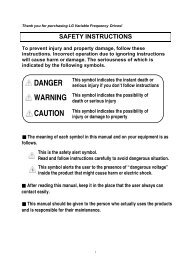
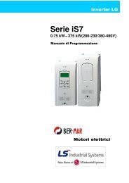
- Page 2 and 3: Thank you for purchasing LS Variabl
- Page 4 and 5: OPERATING PRECAUTIONS(1) Handling a
- Page 6 and 7: Important User Information• The p
- Page 8 and 9: 8.4 3-Wire ........................
- Page 10 and 11: CHAPTER 1 - BASIC INFORMATION & PRE
- Page 12 and 13: 1.3 Product assembling & disassembl
- Page 14 and 15: CHAPTER 2 - INSTALLATION & WIRING2.
- Page 16 and 17: 2.2 DimensionsSV004IG5A-1SV004iG5A-
- Page 18 and 19: SV110iG5A-2 /SV150iG5A-2SV110iG5A-4
- Page 20 and 21: 2.3 Terminal wiring (Control I/O)T/
- Page 22 and 23: 2.4 Specifications for power termin
- Page 24 and 25: WARNING• Use the Type 3 grounding
- Page 26 and 27: 2.6 PNP/NPN selection and connector
- Page 28 and 29: 3.2 Recommended MCCBInverterCapacit
- Page 30 and 31: CHAPTER 4 - PROGRAMMING KEYPAD & BA
- Page 32 and 33: 4.3 Moving to other groups• There
- Page 34 and 35: 4.4 How to change the codes in a gr
- Page 36 and 37: 4.5 Parameter setting• Changing p
- Page 44 and 45: • Frequency setting via potentiom
- Page 46 and 47: • Drive GroupLEDdisplayAddressfor
- Page 48 and 49: • Function group 1LEDdisplayAddre
- Page 50 and 51: • Function group 1LEDdisplayF511)
- Page 52 and 53: • Function group 1LEDdisplayAddre
- Page 54 and 55: • Function group 2LEDdisplayAddre
- Page 56 and 57: • Function group 2LEDdisplayAddre
- Page 58 and 59: • Function group 2LEDdisplayAddre
- Page 60 and 61: • Function group 2LEDdisplayAddre
- Page 62 and 63: • Input/output groupLEDdisplayAdd
- Page 64 and 65: • Input/output groupLEDdisplayAdd
- Page 66 and 67: • Input/output groupLEDdisplayAdd
- Page 68 and 69: • Input/Output GroupLEDdisplayAdd
- Page 71 and 72: CHAPTER 6 - CONTROL BLOCK DIAGRAMFr
- Page 73: 6-3
- Page 76 and 77: Notes:6-6
- Page 78 and 79: • Frequency setting via -10 ~ +10
- Page 80 and 81: • Frequency setting via 0 ~ 20 [m
- Page 82 and 83: • Frequency setting via Digital V
- Page 84 and 85: 7.3 Operating command setting metho
- Page 86 and 87: • Rotating direction select via -
- Page 88 and 89:
FrequencyResetRuncommandWhen H21 is
- Page 90 and 91:
• Multi-Accel/Decel time setting
- Page 92 and 93:
Note that setting Frequency Ref. fo
- Page 94 and 95:
• User V/F pattern operationGroup
- Page 96 and 97:
7.6 Stop method select• Decel to
- Page 98 and 99:
• Skip frequencyGroup Code Parame
- Page 100 and 101:
• Starting DC brakeGroup Display
- Page 102 and 103:
P1P7FX : I 17 = 0JOG : I23=26CM8.3
- Page 104 and 105:
When F65 is 1: It is increased as m
- Page 106 and 107:
Dwell freq.Start freq.FrequencyRunc
- Page 108 and 109:
Group Display Parameter Name Settin
- Page 110 and 111:
• Process PID drive (H54=1)1st/2n
- Page 112 and 113:
8.9 Sensorless Vector ControlGroup
- Page 114 and 115:
8.11 Speed searchGroup Display Para
- Page 116 and 117:
8.12 Auto restart tryGroup Display
- Page 118 and 119:
Used when an inverter operates 2 mo
- Page 120 and 121:
The following table shows the fault
- Page 122 and 123:
8.17 Over voltage trip prevention d
- Page 124 and 125:
8.19 Kinetic energy bufferingGroup
- Page 126 and 127:
8.21 2 Phase PWM driveGroup Display
- Page 128 and 129:
8.24 Parameter read/writeGroup Disp
- Page 130 and 131:
Follow the table below to change th
- Page 132 and 133:
• User display selectGroup Displa
- Page 134 and 135:
9.3 Monitoring fault condition• M
- Page 136 and 137:
9.4 Analog OutputGroup Display Para
- Page 138 and 139:
I56: When 17 {Fault display} is sel
- Page 140 and 141:
• 4: FDT-5 Activated as B contact
- Page 142 and 143:
9.6 Output terminal select at loder
- Page 144 and 145:
Current [%]F51F5260 ETH trip time [
- Page 146 and 147:
For example, set F59 to 3 to make s
- Page 148 and 149:
P1P7P8CMFX : I17 = 0N.O. : I23 = 18
- Page 150 and 151:
H75: DB resistor ED limit setting0
- Page 152 and 153:
11.3 Installation• Connecting the
- Page 154 and 155:
Error code: ASCII (20h ~ 7Fh)Receiv
- Page 156 and 157:
4) Action Request for monitor regis
- Page 158 and 159:
Address Parameter Scale Unit R/W Al
- Page 160 and 161:
Address Parameter Scale Unit Allotm
- Page 162 and 163:
11.8 TroubleshootingRefer to Troubl
- Page 164 and 165:
• Fault Display and InformationKe
- Page 166 and 167:
• Fault remedyKeypaddisplayOver v
- Page 168 and 169:
12.3 Precautions for maintenance an
- Page 170 and 171:
• Input & output ratings: Three P
- Page 172 and 173:
13.2 Temperature Derating Informati
- Page 174 and 175:
CAUTION• Without Parameter Read(H
- Page 176 and 177:
13.6 DeviceNet/Ethernet Communicati
- Page 178 and 179:
TECHNICAL STANDARDS APPLIEDThe stan
- Page 180:
EMI / RFI POWER LINE FILTERSLS inve