- Page 2 and 3:
Thank you for purchasing LS Variabl
- Page 4 and 5:
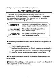
OPERATING PRECAUTIONS(1) Handling a
- Page 6 and 7:
Important User Information• The p
- Page 8 and 9:
8.4 3-Wire ........................
- Page 10 and 11:
CHAPTER 1 - BASIC INFORMATION & PRE
- Page 12 and 13:
1.3 Product assembling & disassembl
- Page 14 and 15:
CHAPTER 2 - INSTALLATION & WIRING2.
- Page 16 and 17:
2.2 DimensionsSV004IG5A-1SV004iG5A-
- Page 18 and 19:
SV110iG5A-2 /SV150iG5A-2SV110iG5A-4
- Page 20 and 21:
2.3 Terminal wiring (Control I/O)T/
- Page 22 and 23:
2.4 Specifications for power termin
- Page 24 and 25:
WARNING• Use the Type 3 grounding
- Page 26 and 27:
2.6 PNP/NPN selection and connector
- Page 28 and 29:
3.2 Recommended MCCBInverterCapacit
- Page 30 and 31:
CHAPTER 4 - PROGRAMMING KEYPAD & BA
- Page 32 and 33:
4.3 Moving to other groups• There
- Page 34 and 35:
4.4 How to change the codes in a gr
- Page 36 and 37:
4.5 Parameter setting• Changing p
- Page 43 and 44:
• Frequency Setting via potentiom
- Page 45 and 46:
CHAPTER 5 - FUNCTION LIST• Drive
- Page 47 and 48:
• Function group 1LEDdisplayAddre
- Page 49 and 50:
• Function group 1LEDdisplayAddre
- Page 51 and 52:
• Function group 1LEDdisplayAddre
- Page 53 and 54:
• Function group 2LEDdisplayAddre
- Page 55 and 56:
• Function group 2LEDdisplayH221)
- Page 57 and 58: • Function group 2LEDdisplayAddre
- Page 59 and 60: • Function group 2LEDdisplayAddre
- Page 61 and 62: • Function group 2LEDdisplayAddre
- Page 63 and 64: • Input/output groupLEDdisplayAdd
- Page 65 and 66: • Input/output groupLEDdisplayAdd
- Page 67 and 68: • Input/Output GroupLEDdisplayAdd
- Page 69: • Input/Output GroupLEDdisplayAdd
- Page 72 and 73: 6.1 Frequency setting1st ReferenceF
- Page 75 and 76: 6.3 Accel/Decel setting and V/F con
- Page 77 and 78: CHAPTER 7 - BASIC FUNCTIONS7.1 Freq
- Page 79 and 80: I6 ~ I10: Setting input range and c
- Page 81 and 82: Group Code Parameter Name Setting U
- Page 83 and 84: 7.2 Multi-Step Frequency settingGro
- Page 85 and 86: • Operating command via FX, RX te
- Page 87 and 88: • Power On Start selectGroup Code
- Page 89 and 90: More precise time unit can be set c
- Page 91 and 92: • Accel/Decel pattern settingGrou
- Page 93 and 94: 7.5 V/F control• Linear V/F patte
- Page 95 and 96: • Manual torque boostGroup Code P
- Page 97 and 98: 7.7 Frequency limit• Frequency li
- Page 99 and 100: CHAPTER 8 - ADVANCED FUNCTIONS8.1 D
- Page 101 and 102: 8.2 Jog operation• Terminal jog o
- Page 103 and 104: • Up-down mode selectGroup Displa
- Page 105 and 106: 8.4 3-WireGroup Display Parameter N
- Page 107: H33: Enter the motor nameplate rate
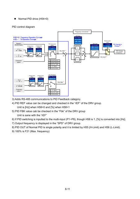
- Page 111 and 112: Sleep FreqWake up levelPID Referenc
- Page 113 and 114: • Factory default by motor rating
- Page 115 and 116: EX) Speed search during Instant Pow
- Page 117 and 118: 8.13 Operating sound select (Carrie
- Page 119 and 120: 8.15 Self-Diagnostic function• Ho
- Page 121 and 122: Selects the self drive in the 2 nd
- Page 123 and 124: Selects the self drive in the 2 nd
- Page 125 and 126: Select 1 and 2 for F70The center va
- Page 127 and 128: CAUTIONIf operation is continued af
- Page 129 and 130: 8.25 Parameter Initialize / Lock•
- Page 131 and 132: CHAPTER 9 - MONITORING9.1 Operating
- Page 133 and 134: 9.2 Monitoring the I/O terminal•
- Page 135 and 136: When the fault condition is reset v
- Page 137 and 138: 9.5 Multi-function output terminal
- Page 139 and 140: • 2: FDT-3 Activated when run fre
- Page 141 and 142: • 12: During operation Activated
- Page 143 and 144: CHAPTER 10 -PROTECTIVE FUNCTIONS10.
- Page 145 and 146: • Overload tripGroup Code Paramet
- Page 147 and 148: 10.4 Output phase loss protectionGr
- Page 149 and 150: Ex 1) The inverter determines the f
- Page 151 and 152: CHAPTER 11 -RS485 COMMUNICATION11.1
- Page 153 and 154: 11.5 Communication protocol (MODBUS
- Page 155 and 156: 2.1) Acknowledge response:ACK Drive
- Page 157 and 158: Address Parameter Scale Unit R/W Al
- Page 159 and 160:
2) Extended Common Area :2.1) Inver
- Page 161 and 162:
2.3) Inverter Memory Control Area (
- Page 163 and 164:
CHAPTER 12 -TROUBLESHOOTING & MAINT
- Page 165 and 166:
12.2 Fault remedyKeypaddisplayOverc
- Page 167 and 168:
• Fault remedyProtective function
- Page 169 and 170:
CHAPTER 13 -SPECIFICATIONS13.1 Tech
- Page 171 and 172:
• OperationOperation modeFrequenc
- Page 173 and 174:
2) Remote Cable (1M,2M,3M,5M)• Re
- Page 175 and 176:
• Conduit KitConduit KitInverter
- Page 177 and 178:
DECLARATION OF CONFORMITYCouncil Di
- Page 179 and 180:
EMI / RFI POWER LINE FILTERSLS inve
- Page 182:
WarrantyMakerModel No.CustomerInfor