Stellar Voyager - Marine Accident Investigation Branch
Stellar Voyager - Marine Accident Investigation Branch
Stellar Voyager - Marine Accident Investigation Branch

You also want an ePaper? Increase the reach of your titles
YUMPU automatically turns print PDFs into web optimized ePapers that Google loves.
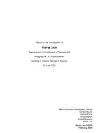
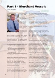
Report on the investigation of<br />
the catastrophic failure of a windlass hydraulic motor<br />
on board<br />
<strong>Stellar</strong> <strong>Voyager</strong><br />
off Tees Bay<br />
resulting in a major injury on<br />
23 March 2009<br />
<strong>Marine</strong> <strong>Accident</strong> <strong>Investigation</strong> <strong>Branch</strong><br />
Mountbatten House<br />
Grosvenor Square<br />
Southampton<br />
United Kingdom<br />
SO15 2JU<br />
Report No 25/2009<br />
December 2009
Extract from<br />
The United Kingdom Merchant Shipping<br />
(<strong>Accident</strong> Reporting and <strong>Investigation</strong>)<br />
Regulations 2005 – Regulation 5:<br />
“The sole objective of the investigation of an accident under the Merchant Shipping<br />
(<strong>Accident</strong> Reporting and <strong>Investigation</strong>) Regulations 2005 shall be the prevention of future<br />
accidents through the ascertainment of its causes and circumstances. It shall not be the<br />
purpose of an investigation to determine liability nor, except so far as is necessary to<br />
achieve its objective, to apportion blame.”<br />
NOTE<br />
This report is not written with litigation in mind and, pursuant to Regulation 13(9) of the<br />
Merchant Shipping (<strong>Accident</strong> Reporting and <strong>Investigation</strong>) Regulations 2005, shall be<br />
inadmissible in any judicial proceedings whose purpose, or one of whose purposes is to<br />
attribute or apportion liability or blame.<br />
Further printed copies can be obtained via our postal address, or alternatively by:<br />
Email: maib@dft.gsi.gov.uk<br />
Tel: 023 8039 5500<br />
Fax: 023 8023 2459<br />
All reports can also be found on our website:<br />
www.maib.gov.uk
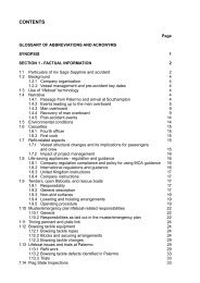
CONTENTS<br />
GLOSSARY OF ABBREVIATIONS, ACRONYMS AND TERMS<br />
Page<br />
SYNOPSIS 1<br />
SECTION 1 - FACTUAL INFORMATION 3<br />
1.1 Particulars of <strong>Stellar</strong> <strong>Voyager</strong> and accident 3<br />
1.2 Narrative 4<br />
1.2.1 Background 4<br />
1.2.2 The accident 4<br />
1.2.3 Post accident 7<br />
1.3 Crew 8<br />
1.3.1 General 8<br />
1.3.2 Master 8<br />
1.3.3 Chief officer 8<br />
1.3.4 Bosun 8<br />
1.3.5 Training and familiarisation 9<br />
1.4 Safety management 9<br />
1.5 Windlass and anchor system 9<br />
1.5.1 Anchor and cable 9<br />
1.5.2 Windlass machinery 9<br />
1.5.3 Hydraulic drive motor 10<br />
1.5.4 Combined pressure relief and motion control valve 12<br />
1.5.5 Hydraulic circuit 12<br />
1.5.6 Brakes 12<br />
1.5.7 Technical instructions and guidance 14<br />
1.6 Tests and evaluations 15<br />
1.6.1 Preliminary inspection 15<br />
1.6.2 Independent tests 16<br />
1.6.3 Metallurgical examination 16<br />
1.6.4 Oil analysis 17<br />
1.7 Windlass requirements 18<br />
1.7.1 SOLAS 18<br />
1.7.2 IACS 18<br />
1.7.3 American Bureau of Shipping (ABS) 18<br />
1.8 Advice on anchoring operations 19<br />
1.8.1 The Oil Companies International <strong>Marine</strong> Forum (OCIMF) 19<br />
1.8.2 Nautical Institute 19<br />
1.9 Previous incidents 19<br />
SECTION 2 – ANALYSIS 21<br />
2.1 Aim 21<br />
2.2 Damage mechanism 21<br />
2.2.1 Overpressure 21<br />
2.2.2 Over-speed 23<br />
2.2.3 Seizure 24<br />
2.2.4 Summary 24
2.3 Machinery requirements 24<br />
2.4 Windlass operation 25<br />
2.5 Maintenance and Information 26<br />
SECTION 3 - CONCLUSIONS 28<br />
3.1 Safety issues directly contributing to the accident which have<br />
resulted in recommendations 28<br />
3.2 Safety issues identified during the investigation which have not<br />
resulted in recommendations but have been addressed 28<br />
SECTION 4 - ACTION TAKEN 29<br />
4.1 MAIB Safety Bulletin 29<br />
4.2 Chevron Shipping Company 29<br />
SECTION 5 - RECOMMENDATIONS 30<br />
Figures and Annexes<br />
Figure 1 – Location of accident<br />
Figure 2 – Gap between chain link and stopper<br />
Figure 3 – Positions of crew members at the time of the accident<br />
Figure 4 – Fragment of hydraulic motor casing found 40m aft of the starboard<br />
windlass<br />
Figure 5 – Starboard winch-windlass<br />
Figure 6 – Hydraulic drive motor<br />
Figure 7 – Bent axis axial piston displacement hydraulic motor<br />
Figure 8 – Hydraulic circuit with the motor reversing when chain renders<br />
Figure 9 – Spring-loaded, hydraulic cylinder for band brakes<br />
Figure 10 – Cylinder block<br />
Figure 11 – Secondary cracks on a cylinder bore<br />
Figure 12 – Predominant damage on one side of the cylinder housing<br />
Figure 13 – Movement of the ship during the accident<br />
Annex A – Survey Report no.091909<br />
Annex B – The Test House Laboratory Report<br />
Annex C – Oil analysis<br />
Annex D – MAIB Safety Bulletin
GLOSSARY OF ABBREVIATIONS, ACRONYMS AND TERMS<br />
AB - Able bodied seaman<br />
ABS - American Bureau of Shipping<br />
BVFS - Bundesverband Freier Sachverstandiger e.V<br />
cm - centimetre<br />
cm 3 - cubic centimetre<br />
Focsle - Forecastle<br />
GL - Germanischer Lloyd<br />
IACS - International Association of Classification Societies<br />
ID - Internal diameter<br />
ISO - International Standards Association<br />
JSA - Job Safety Analysis<br />
kg - kilogramme<br />
kN - kilo Newton<br />
kW - kilowatt<br />
l/min - Litres per minute<br />
LPG - Liquefied petroleum gas<br />
m - metre<br />
m/min - metres per minute<br />
mm - millimetre<br />
N/mm 2 - Newtons per squared millimetre<br />
OCIMF - Oil Companies International <strong>Marine</strong> Forum<br />
OS - Ordinary Seaman<br />
RPM - Revolutions per minute
SMS - Safety management system<br />
SOLAS - International Convention for the Safety of Life at<br />
Sea<br />
Toolbox meeting - An on-site risk assessment carried out by all team<br />
members prior to a job or operation, in order to<br />
arrive at a common understanding of the hazards<br />
involved and institute appropriate control measures<br />
and risk mitigation strategies<br />
UHF - Ultra high frequency<br />
UKAS - United Kingdom accreditation service<br />
UR - Unified requirement<br />
UTC - Universal Co-ordinated Time<br />
UTS - Ultimate tensile strength<br />
VMT - Vessel management team<br />
Times: All times used in this report are UTC unless otherwise stated
SYNOPSIS<br />
On 23 March 2009, the starboard windlass hydraulic motor on<br />
board the oil tanker Stella <strong>Voyager</strong> exploded as the vessel was<br />
attempting to recover her starboard anchor in adverse weather and<br />
sea conditions, off Tees Bay, UK. Fragments of the motor and its<br />
casing seriously injured the windlass operator, who was evacuated<br />
to hospital in Middlesborough by helicopter, where he was treated<br />
for a broken leg and injuries to his groin.<br />
The investigation identified that the catastrophic failure of the<br />
windlass, which was manufactured by Friedrich Kocks GmbH,<br />
resulted from the anchor chain being ‘heaved in’ under considerable tension,<br />
exceeding the machinery’s safe operating limit. Examination of the failed components<br />
indicated that the windlass had over-pressurised.<br />
This accident is one of a series of recent catastrophic failures of anchor windlass<br />
motors supplied by TTS Kocks GmbH and other manufacturers. The number and<br />
frequency of these failures is a serious cause for concern, and on 17 August 2009,<br />
the MAIB, together with the Australian Transport Safety Bureau, the Bundesstelle<br />
für Seeunfalluntersuchung (Germany) and the Bahamas Maritime Authority, issued<br />
a Safety Bulletin highlighting the failures and providing guidance on how they can<br />
be avoided. It made an urgent safety recommendation to TTS Kocks GmbH aimed<br />
at identifying the technical causes of the failure of its machinery and determining<br />
technical solutions for preventing similar accidents in the future. TTS Kocks GmbH has<br />
partially rejected the recommendation. The Chief Inspector of <strong>Marine</strong> <strong>Accident</strong>s has<br />
written to TTS Kocks GmbH urging them, in the interests of safety, to reconsider the<br />
recommendation.<br />
The American Bureau of Shipping has been recommended to submit a proposal to<br />
the International Association of Classification Societies which seeks to ensure: a<br />
revision of its technical requirement for windlass hydraulic motors in order to prevent<br />
the catastrophic failure of this type of equipment; and class approval of equipment<br />
is conditional on thorough technical investigation into the causes of catastrophic<br />
failures being conducted by equipment manufacturers whenever these occur. A<br />
recommendation has also been made to the Oil Companies International <strong>Marine</strong><br />
Forum with the aim of providing guidance on weighing anchor, particularly with regard<br />
to the safe operation of windlasses. A further recommendation has been made to TTS<br />
Kocks GmbH intended to improve the technical and operational information it provides<br />
when supplying windlass machinery.<br />
1
2<br />
<strong>Stellar</strong> <strong>Voyager</strong>
SECTION 1 - FACTUAL INFORMATION<br />
1.1 PARTICULARS OF STELLAR VOYAGER AND ACCIDENT<br />
Vessel details<br />
Registered owner : Ocean Leasing (No 2) Limited, London<br />
Operators : Chevron Tankers Limited, London<br />
Port of registry : Nassau<br />
Flag : Bahamas<br />
Type : Oil tanker<br />
Built : 2003, Korea<br />
Classification society : American Bureau of Shipping (ABS)<br />
Construction : Steel<br />
Length overall : 234.88m<br />
Gross tonnage : 58,088<br />
Engine power and/or type : MAN B&W, 13,560kW<br />
Anchor windlass : Friedrich Kocks GmbH, Germany<br />
(Acquired by TTS <strong>Marine</strong> ASA, Norway in 2005<br />
and renamed TTS Kocks GmbH)<br />
<strong>Accident</strong> details<br />
Time and date : 2256 on 23 March 2009<br />
Location of incident : 54º 41.6N, 001º 03.5W, 4nm north east of the<br />
entrance to the River Tees, England<br />
Persons on board : 28<br />
Injuries : 1<br />
Damage : Catastrophic failure of the starboard winchwindlass<br />
hydraulic motor<br />
3
4<br />
1.2 NARRATIVE<br />
1.2.1 Background<br />
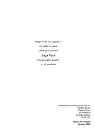
At 1742 on 22 March 2009, <strong>Stellar</strong> <strong>Voyager</strong> anchored off Tees Bay, England<br />
(Figure 1). The starboard anchor was used with 8 shackles1 of anchor chain in<br />
the water. When the anchor chain stopper was engaged, a 10cm gap was left<br />
between the stopper and a chain link to enable any slippage in the drum band<br />
brake to be quickly identified (Figure 2). The depth of water was about 38m.<br />
The vessel, which was in ballast with a 2m stern trim, was expected to berth in<br />
Tees Port on about 27 March 2009.<br />
1.2.2 The accident<br />
During the evening of 23 March, the weather and sea conditions began to<br />
deteriorate; the wind was north-north west at 20 knots and there was a 2m<br />
swell. Shortly after the second officer took over the bridge watch at 2000, he<br />
instructed the duty able bodied seaman (AB) to inspect the anchor chain every<br />
30 minutes.<br />
At 2030, the AB reported by ultra high frequency (UHF) radio that the anchor<br />
chain was ‘heavy’ to ‘very heavy’. He then returned to the bridge and agreed<br />
with the second officer that he would remain on the focsle after his next<br />
inspection because he found it very difficult to walk on deck in the strong wind.<br />
At 2100, the AB reported that the gap at the chain stopper was still around<br />
10cm and the chain was ‘very heavy’.<br />
By 2145, the wind had increased to 28 knots. At about this time, the master<br />
visited the bridge and left instructions in his night order book that he was to<br />
be called if: the gap between the chain link and stopper was closed; the wind<br />
increased to 40 knots or more; or, the vessel dragged anchor. The master was<br />
aware that the wind was forecast to decrease overnight.<br />
At 2230, the duty AB heard the chain cable suddenly tension on the windlass.<br />
On investigation, he found that the gap between the chain stopper and the link<br />
had closed, and immediately informed the bridge. The second officer checked<br />
that the vessel was not dragging her anchor and also alerted the master. The<br />
master arrived on the bridge at 2240 and ordered the duty AB to start the<br />
windlass hydraulic system; he also called anchor stations.<br />
The chief officer soon joined the AB on the focsle, which was well lit, and told<br />
him to engage the windlass gear. The bosun and two ordinary seamen (OS)<br />
also arrived on the focsle. Communication between the master and the chief<br />
officer was via UHF radio but, because the master had difficulty hearing the<br />
chief officer due to the background noise caused by the wind, he often repeated<br />
what he had heard and asked the chief officer to confirm its accuracy. The<br />
positions of the anchor party on the focsle are shown in Figure 3.<br />
1 One shackle = 27.432m or 90 feet
Reproduced from Admiralty Chart BA 2567 by permission of<br />
the Controller of HMSO and the UK Hydrographic Office<br />
Figure 1<br />
Location of accident<br />
5
6<br />
Gap between chain link and stopper<br />
Bosun<br />
Stbd windlass<br />
hydraulic motor<br />
10cm<br />
8m<br />
Positions of crew members at the time of the accident<br />
Figure 2<br />
OS1<br />
Figure 3<br />
OS2<br />
Chief Officer
At 2251, the chief officer informed the master that the anchor chain was at<br />
‘11 o'clock’ and ‘long stay’. The master put the engine to dead slow ahead and<br />
told the chief officer to heave in when the anchor chain became slack. The<br />
engine was left running ahead for about 1 minute, which resulted in the anchor<br />
chain becoming ‘up and down’ as it slackened.<br />
Just before 2254, the chief officer signalled to the bosun by hand to heave<br />
in on the windlass. However, the bosun was unable to release the brake on<br />
the windlass drum. The chief officer noticed that the spindle for the hydraulic<br />
actuating cylinder was not adjusted correctly and, assisted by the Ordinary<br />
Seamen, turned the wheel to re-align the spindle. This allowed the brake to be<br />
released. The bosun again tried to heave in the anchor chain but, after between<br />
eight and ten links were recovered onto the deck, the anchor chain started to<br />
render (pay out). To stop this movement, the bosun put the windlass operating<br />
lever to neutral and applied the brake. He also informed the chief officer that the<br />
chain was ‘very heavy’.<br />
At 2256:13, the chief officer informed the master that the chain was ‘12 o’clock,<br />
long way’. Eight seconds later, the master put the main engine to dead slow<br />
ahead and, by 2256:33, the engine reached its intended speed. During this<br />
short period, the bosun attempted to heave in by setting the operating lever<br />
to maximum displacement but the chain rendered soon after several links had<br />
been brought on deck. The bosun put the lever back to neutral and applied the<br />
brake to check this movement. During a further attempt, the chain again started<br />
to render and the starboard windlass’s hydraulic motor exploded without warning<br />
at 2256:41. The anchor chain ran out very quickly and about 1 shackle of chain<br />
cable was released into the water before it could be stopped by the band brake.<br />
Fragments of the motor’s cast iron casing were blown with considerable force<br />
away from the windlass, some of which struck and seriously injured the bosun,<br />
who immediately fell to the deck. One fragment (Figure 4) measuring 5.7cm x<br />
4.4cm, with a maximum thickness of 1.8cm and weighing 148g, was found on<br />
the deck 40m aft of the windlass.<br />
1.2.3 Post accident<br />
The general alarm was sounded at 2259, and the bosun was carried on a<br />
stretcher to the ship’s hospital. He was in severe pain. The master quickly<br />
alerted Humber coastguard which connected him to a hospital in Aberdeen.<br />
On medical advice, the bosun was given 5mg of morphine and the coastguard<br />
arranged for his evacuation. By 0048 on 24 March 2009, the bosun had been<br />
winched into a rescue helicopter which took him to the James Cook University<br />
Hospital in Middlesbrough. He had suffered a broken left tibia and injuries in<br />
the area of his right groin. He was discharged from the hospital on 27 March<br />
but was not well enough to return to The Philippines for a further 3 weeks. The<br />
bosun was not expected to be able to return to work until the end of 2009.<br />
7
8<br />
1.3 CREw<br />
Fragment of hydraulic motor casing found 40m aft of the starboard windlass<br />
1.3.1 General<br />
The crew comprised several nationalities. The senior officers were mostly<br />
Europeans and the ratings were all Filipinos. The common language on board<br />
was English.<br />
1.3.2 Master<br />
The master was Italian and had been employed by Chevron for 19 years, the<br />
last 4 of which had been as master. He joined <strong>Stellar</strong> <strong>Voyager</strong> in February<br />
2009, and had weighed2 anchor on board the vessel on two previous occasions,<br />
off Tees Bay on 12 March and off Pembroke, Wales on 19 March.<br />
1.3.3 Chief officer<br />
The chief officer was Polish and joined Chevron in 2006 as a second officer.<br />
He was promoted to chief officer in June 2007 and joined <strong>Stellar</strong> <strong>Voyager</strong> on 27<br />
January 2009. He had previously worked on board the vessel from September<br />
to November 2008.<br />
1.3.4 Bosun<br />
The bosun was Filipino and had been employed by Chevron for 17 years, the<br />
last 4 of which were as a bosun. He joined <strong>Stellar</strong> <strong>Voyager</strong> in January 2009.<br />
This was his second contract on board the vessel and he had also previously<br />
sailed on her sister ship Neptune.<br />
2 Weighing anchor: Retrieving anchor using the windlass<br />
Figure 4
1.3.5 Training and familiarisation<br />
All crew joining the vessel were required to complete a <strong>Marine</strong> Employees’<br />
Indoctrination Program, which included a check box titled Anchoring and Windlass<br />
Operation. However, training in the use of the windlass machinery relied on ‘on<br />
the job’ training from more experienced crew, rather than specific instruction.<br />
1.4 SAFETY MANAGEMENT<br />
The ship’s safety management system (SMS) included a section titled Managing<br />
Job Safety, the purpose of which was to:<br />
Ensure that shipboard tasks are carried out safely and efficiently in order to<br />
achieve our goal of zero incidents.<br />
All jobs, including those considered to involve tolerable or lower risks, were<br />
required to be pre-planned and, as a minimum, a toolbox meeting of all those<br />
involved was recommended. A written job safety analysis (JSA) was required<br />
for all jobs the vessel management team (VMT) considered posed more than a<br />
tolerable level of risk. <strong>Stellar</strong> <strong>Voyager</strong>’s VMT conducted daily work meetings on<br />
board, with the chief officer and chief engineer holding parallel meetings for their<br />
respective departments. A daily planning white board was also used during these<br />
meetings to identify the risk associated with each job and the countermeasures to<br />
be put in place. All available crew attended these meetings. Neither a JSA nor a<br />
toolbox meeting was conducted prior to weighing anchor on 23 March.<br />
1.5 wINDLASS AND ANChOR SYSTEM<br />
1.5.1 Anchor and cable<br />
<strong>Stellar</strong> <strong>Voyager</strong> was fitted with two stockless, high holding power anchors, each<br />
weighing 10,125kg and attached to 13 shackles of 87mm diameter grade K3 steel<br />
chain cable on each side. Each shackle of cable weighed 4610kg. The chain<br />
was connected to the anchor with a swivel and Kenter joining shackle.<br />
1.5.2 windlass machinery<br />
The anchor windlass system was supplied by Friedrich Kocks GmbH, Germany.<br />
It was electro hydraulically powered and fitted with two independent split drum<br />
winches on either side (Figure 5). The windlass was driven by a hydraulic motor<br />
manufactured by Bosch Rexroth AG, via planetary gears which drove a main gear<br />
wheel connected to the anchor chain gypsy wheel through a shaft and coupling<br />
arrangement. This double reduction gearing provided a speed ratio of 1168:1.<br />
Each windlass had a maximum capacity of 540kN and a nominal speed of<br />
9m/min. The brake capacity was 2475kN.<br />
The design of the anchor windlass system was approved by the vessel’s<br />
classification society, the American Bureau of Shipping (ABS) in December 2002.<br />
The system was then tested in accordance with the requirements of the society’s<br />
rules during sea trials in 2003, and was found to be satisfactory.<br />
9
1.5.3 hydraulic drive motor<br />
The hydraulic drive motor (Figure 6) was a bent axis axial piston variable<br />
displacement type. It was bi-directional and was capable of operating at<br />
maximum speeds of 3550rpm at 107cm3 displacement and 6300rpm at 0cm3 displacement, but had been adjusted to operate at maximum speeds of<br />
1725rpm at 107cm3 displacement and 4325rpm at 43cm3 displacement. The oil<br />
flow was constant at 190 l/min. The motor output was adjusted by varying the<br />
position of a ‘lens plate’ which varied the stroke length of the seven pistons in<br />
the cylinder. The motor was therefore capable of achieving infinite combinations<br />
of torque and speed. The central bore of the cylinder carried a hollow springloaded<br />
pin which kept the cylinder aligned to its rotational axis. A diagram<br />
showing the internal components of the motor is at Figure 7.<br />
10<br />
Starboard winch-windlass<br />
The planetary gear box was manufactured by Zoellern GmbH & Co KG and<br />
was fitted with a self contained oil bath for splash lubricating the gears. The<br />
oil was required to be changed yearly, but had not been changed since the<br />
machinery’s installation. The main gear case oil had also not been changed<br />
since installation.<br />
Figure 5<br />
The motor’s components were made of normalised engineering steel and its<br />
outer casing was made of grey flake cast iron. The outer casing was not fitted<br />
with a pressure relief arrangement except for an open drain line to allow leaked<br />
oil to drain to a tank.
Drive<br />
shaft<br />
Ball head<br />
of piston<br />
Centre<br />
drive pin<br />
Hydraulic drive motor<br />
Cylinder<br />
Piston<br />
Bent axis axial piston displacement hydraulic motor<br />
Figure 6<br />
Combined pressure<br />
relief and<br />
counterbalance valve<br />
Lens plate<br />
Figure 7<br />
11
1.5.4 Combined pressure relief and motion control valve 3<br />
12<br />
A combined pressure relief and motion control valve set to open at 280 bars<br />
pressure, supplied by Bucher Hydraulics, Switzerland, was fitted directly on top<br />
of the hydraulic motor (Figure 6). The main hydraulic pipes had an internal<br />
diameter (ID) of 21.5mm at the inlet to the motor, and the outlet from the relief<br />
valve was connected through a pipe of approximately 15mm ID which reduced<br />
to 8.5 mm ID and finally to approximately 5mm at the inlet (point MPA at Figure<br />
8). The relief valve was designed to relieve only instantaneous peaks of<br />
pressure in the system. During factory tests, when the flow rate was increased<br />
from 0.5 l/min to 200 l/min over a 10s period, the valve opened at 280 bars<br />
and the pressure continued to rise to 380 bars. The flow of 200 l/min was<br />
maintained for 1 to 2 seconds before gradually reducing to a level which allowed<br />
the valve to close.<br />
1.5.5 hydraulic circuit<br />
The power pack consisted of three electric motor driven hydraulic pumps<br />
delivering a constant pressure of 245 bars. Depending on the position<br />
(minimum to maximum) and direction (heave, stop or lower) of the operating<br />
lever, the spool valve (Figure 8) allowed a proportionate amount of oil to the<br />
appropriate inlet of the hydraulic motor. In addition, a proportionate amount<br />
of pilot oil was supplied at point X (Figure 8) to achieve the required angular<br />
position of the lens plate. All the components in the control system were<br />
supplied by Buchholz Hydraulik GmbH.<br />
1.5.6 Brakes<br />
A set of spring-loaded multiple disk brakes was located between the planetary<br />
gears and the main gear wheel, which automatically released when sufficient<br />
hydraulic pressure had developed in the system. These brakes hold the anchor<br />
chain in place when the band has been released but the operating lever is in the<br />
stop position.<br />
A band brake on the cable drum was released by the movement of a ‘dead<br />
man’ lever which applied hydraulic pressure to the brake’s actuators. When the<br />
lever was released, it automatically returned to a position which relieved the<br />
hydraulic pressure in the brake cylinder and allowed the brake to close under<br />
spring force. The spring force was adjusted by a spindle on the brake cylinder<br />
(Figure 9). To release the brake, a groove on the spindle needed to be aligned<br />
with an arrow etched on a metal plate fixed to the top of the cylinder. If the<br />
arrow and groove were not aligned, the flow of hydraulic oil to the brake release<br />
mechanism was obstructed, which prevented the brake from being released.<br />
After the linings of the band brake on the vessel’s starboard windlass were<br />
renewed in dry dock in August 2008, difficulties were experienced in fully<br />
releasing the brake until the hydraulic brake cylinder activation spindle and<br />
valve were renewed by the ship’s crew on 11 March 2009.<br />
3 Motion control valve is more commonly known as counter balance valve. It is also referred to as a ‘lockvalve’.
Point MPA<br />
Oil flow<br />
through motor<br />
Oil flow to<br />
maintain sufficient<br />
oil in system<br />
Spool valve<br />
Point X<br />
pilot oil<br />
Figure 8<br />
13<br />
Hydraulic circuit with the motor reversing when chain renders
1.5.7 Technical instructions and guidance<br />
Kocks manual OM-01 Windlass & Mooring Winches was divided into six<br />
sections. It contained no, or very little description, instruction, or warning about<br />
the following:<br />
• Lubricating oil grade and maintenance instructions for the planetary gear<br />
system.<br />
14<br />
Spring-loaded, hydraulic cylinder for band brakes<br />
• Bosch Rexroth hydraulic motor or pump.<br />
• Local and remote hydraulic pump control stations including idling mode<br />
and starting sequence.<br />
Figure 9
• Performance characteristics of band brakes.<br />
• Hydraulic circuit diagrams.<br />
• Precautions to be exercised during heaving in and lowering anchor.<br />
• Risk of injury due to catastrophic failure of hydraulic components.<br />
Several technical drawings contained instructions in German for which no<br />
English translations were available.<br />
1.6 TESTS AND EVALUATIONS<br />
1.6.1 Preliminary inspection<br />
Preliminary onboard examination of the damaged hydraulic motor revealed very<br />
little evidence of torsional failure of its components. The majority of the damage<br />
was local to the hydraulic motor and its casing. The centre drive pin had<br />
sheared at its mid point where its bore increased substantially and, although<br />
three of the seven pistons were found intact, the remaining four were missing.<br />
The three pistons showed signs of hard contact between the ball heads and<br />
drive shaft, and the bodies of the pistons showed what appeared to be incipient<br />
service wear or spalling type damage (Annex B, Figure 42). Of the seven<br />
bores in the cylinder block, five adjacent bores had disintegrated (Figure 10).<br />
Except for the damage to the first roller bearing on the motor output shaft, a<br />
seized drive gear on the planetary gear train and overheating of the disc brake<br />
plates, no other damage was observed beyond the hydraulic motor.<br />
Cylinder block<br />
Figure 10<br />
15
1.6.2 Independent tests<br />
On instruction from Chevron, the vessel’s operator, TTS Kocks commissioned<br />
Zeppelin Baumaschinen GmbH to carry out independent evaluation of the<br />
failed components. In turn, Zeppelin contracted Bundesverband Freier<br />
Sachverstandiger e.V (BVFS) to carry out the work. The report of this<br />
evaluation which, apart from a functional test of the combined pressure relief<br />
and motion control valve, was based on visual examination, included:<br />
The damage to the hydraulic motor presented to me for examination was<br />
caused by a too high rotation speed. [sic]<br />
16<br />
An extremely high rotation speed brought in through the drive shaft<br />
caused a reversal of the pressure ratio. These combined conditions of<br />
rotation speed, low-pressure and pressure, which could not be supported<br />
any more, led to a destruction of the hydraulic motor from the interior.<br />
[sic]<br />
A functional test at a hydraulic test stand showed the following result:<br />
The lock valve functioned normally. The pressure control valve could not<br />
hold the pressure of 280 bar. [sic]<br />
The report, which includes a number of photographs of the damaged<br />
components and casing, was written in German but translated into English<br />
(Annex A) before being forwarded to the MAIB and Chevron. Independent<br />
translations of the report commissioned by the MAIB and Chevron did not<br />
identify any errors in the original translation.<br />
1.6.3 Metallurgical examination<br />
On receipt of the BVFS report, the MAIB in co-operation with Chevron,<br />
commissioned The Test House (Cambridge) Ltd to carry out detailed<br />
metallurgical examination of the failed components in order to determine the<br />
primary cause of failure.<br />
The metallurgist’s report (Annex B) stated that all but one of the twenty four<br />
pieces remaining from the hydraulic motor’s cast iron casing showed evidence<br />
of impact damage. There were also signs of post incident impact damage on<br />
several components of the motor.<br />
The laboratory tests did not find any evidence of manufacturing or metallurgical<br />
defects including pre-incident fatigue cracks. The failed cylinder block appeared<br />
to have experienced brittle fracture along the longitudinal axis of the cylinder<br />
bores, and there was very little evidence of plastic deformation of the material,<br />
although the cylinder block was constructed of engineering type steel that had<br />
entered service in a normalised type condition.
Further tests were requested by the MAIB to understand the behaviour of the<br />
cylinder material under tensile loading. A piece of steel from the undamaged<br />
side of the cylinder block was subjected to standard tensile tests. Typical<br />
behaviour expected of this grade of steel was observed with a yield stress 4 of<br />
371N/mm 2 and ultimate tensile stress 5 (UTS) of 646N/mm 2 .<br />
The Test House report concluded:<br />
Based on the evidence, we conclude that catastrophic failure of the<br />
hydraulic motor had resulted from gross over-pressurisation of its cylinder<br />
block. The block had fractured in response to an unsustainably high hoop<br />
stress6 acting on the cylinder walls. A number of pieces had fractured<br />
from the block in a brittle manner and these in turn had impacted with and<br />
fractured the motors outer grey flake graphite cast iron casing.<br />
The report also stated:<br />
We would also suggest that there may be better materials for the motors<br />
casing than grey flake graphite cast iron. The use of either a cast steel<br />
or a grade of Ductile Iron with guarantees on both fracture elongation<br />
and Charpy toughness, would offer better chances of both pressure and<br />
fragment containment in conditions of off design overload or impact.<br />
1.6.4 Oil analysis<br />
The hydraulic oil and main gear case oil were tested at a fluid testing laboratory<br />
approved by United Kingdom Accreditation Service (UKAS). The hydraulic oil<br />
cleanliness was found to be at the alert level measuring 21/19/167 using the<br />
International Standards Organisation (ISO) 4406 benchmark. The instruction<br />
manual for the Bosch Rexroth hydraulic motor included:<br />
To ensure functional reliability of the axial piston unit, the hydraulic fluid<br />
must have a cleanliness level of at least 20/18/15 according to ISO 4406.<br />
The main gear oil was found to contain 3% saline water and its viscosity was<br />
double that of the reported grade of oil in use. Further microscopic analysis<br />
of the oil showed evidence of fatigue wear and poor lubrication due to the<br />
presence of grease and sea water. The results of the oil analysis are at<br />
Annex C.<br />
4 Yield stress: The stress at which the material deforms, permanently changing from elastic deformation to<br />
the point of plastic deformation and beyond.<br />
5 UTS: The Ultimate tensile stress (UTS) is the highest load applied in breaking a tensile test piece divided<br />
by the original cross-sectional area of the test piece.<br />
6 Hoop stress is the circumferential stress in a cylindrically shaped part as a result of internal or external<br />
pressure.<br />
7 ISO 4406 is the international standard for measuring and reporting particulate contamination levels in<br />
fluids. It is a count of the number of particles per unit volume greater than 4, 6 and 14 microns.<br />
17
1.7 wINDLASS REqUIREMENTS<br />
1.7.1 SOLAS<br />
The SOLAS Convention does not specify requirements for anchor windlasses,<br />
but Chapter II-I Part C Regulation 26 Machinery installations includes:<br />
The machinery, boilers and other pressure vessels, associated piping<br />
systems and fittings shall be of a design and construction adequate for<br />
the service for which they are intended and shall be so installed and<br />
protected as to reduce to a minimum any danger to persons on board,<br />
due regard being paid to moving parts, hot surfaces and other hazards.<br />
The design shall have regards to materials used in construction, the<br />
purpose for which the equipment is intended, the working conditions to<br />
which it will be subjected and the environmental conditions on board.<br />
18<br />
And Regulation 27 Machinery states:<br />
Where main or auxiliary machinery including pressure vessels or any<br />
parts of such machinery are subject to internal pressure and may be<br />
subject to dangerous overpressure, means shall be provided where<br />
practicable to protect against such excessive pressure.<br />
Regulation 27 also requires that if a risk of over-speeding has been identified,<br />
means should be provided to prevent the machinery from exceeding the safe<br />
speed.<br />
1.7.2 IACS<br />
The International Association of Classification Societies (IACS) in Unified<br />
Requirements (UR) – A, under the heading Equipment states:<br />
The anchoring equipment required herewith is intended for temporary<br />
mooring of a vessel within a harbour or sheltered area when the vessel is<br />
awaiting berth, tide, etc.<br />
The equipment is therefore not designed to hold a ship off fully exposed<br />
coasts in rough weather or to stop a ship which is moving or drifting. In<br />
this condition the loads on the anchoring equipment increase to such a<br />
degree that its components may be damaged or lost owing to the high<br />
energy forces generated, particularly in large ships.<br />
1.7.3 American Bureau of Shipping (ABS)<br />
ABS rules require that windlasses be inspected during fabrication, and tested<br />
and certified at the manufacturer’s facilities. They also require each windlass<br />
to be tested under working conditions after their installation on board. Onboard<br />
tests include: braking; clutch functioning; lowering and hoisting of chain cable<br />
and anchor; proper riding of the chain over the chain lifter; proper transit of the<br />
chain through the hawse pipe and the chain pipe including stowage. Brakes<br />
are required to be able to hold 3 shackles of cable hanging free, and a windlass<br />
must be capable of hoisting this length of cable at a mean speed of 9m/min.
ABS Rules, Part 4, Chapter 6, Section 7-3 Hydraulic Oil Systems states:<br />
Hydraulic oil systems fitted in self-contained equipment not associated<br />
with propulsion and manoeuvring of the vessel (e.g., a crane) and<br />
completely assembled by the equipment manufacturer need not comply<br />
with this subsection. Such hydraulic oil systems, however, are to comply<br />
with the accepted industry standards.<br />
Regarding requirements for relieving arrangements for hydraulic systems, the<br />
society’s rules state:<br />
Relief valves are to be fitted to protect the system from overpressure. The<br />
relieving capacity is not to be less than full pump flow with a maximum<br />
pressure rise in the system of not more than 10% of the relief valve<br />
setting.<br />
1.8 ADVICE ON ANChORING OPERATIONS<br />
1.8.1 The Oil Companies International <strong>Marine</strong> Forum (OCIMF)<br />
OCIMF publication Anchoring systems and Procedures for Large Tankers (1st edition 1982) does not contain any guidance on weighing anchor except:<br />
By waiting too long, weighing anchor in bad weather can become a<br />
hazardous operation for those on the forecastle head.<br />
And, when discussing how to monitor tension on an anchor cable:<br />
The best indicator of such stress is the behaviour of the anchor cable.<br />
Personnel should check this visually, looking for things such as amount of<br />
change in the cable catenary or for unusual effects, such as shocks when<br />
the cable tightens.<br />
1.8.2 Nautical Institute<br />
The Nautical Institute publication Anchoring Large Vessels: A new approach<br />
alerts seafarers to the ease with which the windlass motor could be subjected<br />
to overload and consequent failure, if the chain is not maintained vertical while<br />
walking back the anchor8 . It also states that the anchor and cable are capable<br />
of holding a loaded vessel in a current of three knots and a wind of 28 knots,<br />
maximum.<br />
1.9 PREVIOUS INCIDENTS<br />
In the period from 1994 to 2002, the MAIB conducted preliminary examination of<br />
six cases of hydraulic drive motors of mooring winches failing in operation. No<br />
injuries were caused by these accidents. Since 2007, the MAIB has been made<br />
aware of the catastrophic failure of a number of high pressure hydraulic anchor<br />
windlasses.<br />
• On 25 June 2007, the tanker Young Lady started to drag her anchor in<br />
Tees Bay, UK. The vessel was in ballast, the wind speed was in excess<br />
of 40 knots and there was a heavy northerly swell. The master decided<br />
8 Walking back the anchor: lowering the anchor under power using the windlass motor<br />
19
20<br />
to weigh anchor and depart, but during the operation the Nippon Pusnes<br />
windlass hydraulic motor exploded and the cable ran out to the bitter end.<br />
The vessel continued to drag her anchor until the anchor flukes snagged<br />
on a submerged gas pipeline (MAIB investigation report 3/2008).<br />
The technical investigation carried out by London Offshore Consultants,<br />
on the failed hydraulic motor components, states:<br />
Reason for failure (High pressure shock to hydraulic system)<br />
The hydraulic motor has been exposed to extremely high pressure<br />
on one side of the motor. Evidence of this pressure can be seen by:<br />
1) the failure of the rear port on the valve housing, 2) failure of the<br />
crankshaft drum and 3) distortion of the displacement piston. The<br />
pressure required to burst the valve housing would be in the region of<br />
800 BAR. This failure indicates that the motor was being operated in the<br />
maximum displacement [anchor mode] when the failure occurred. This is<br />
supported by the missing blanking plug and the damage to the maximum<br />
displacement piston and the drum.<br />
• On 13 December 2008, the hydraulic motor casing of a TTS Kocks high<br />
pressure windlass on board the Hong Kong, China registered container<br />
ship APL Sydney, fractured as the vessel was heaving in her anchor in<br />
Melbourne Bay, Australia shortly after the anchor had dragged in gale<br />
force winds and had ruptured a submerged gas pipeline. There were no<br />
injuries. This accident is being investigated by the Australian Transport<br />
Safety Bureau which also identified another failure of an anchor windlass<br />
hydraulic motor while investigating the grounding of the Singapore<br />
registered woodchip carrier Crimson Mars in May 2006.<br />
• On 19 May 2009, the hydraulic motor of a TTS Kocks high pressure<br />
windlass on board a German registered LPG vessel exploded as the<br />
vessel was heaving in her anchor off the coast of Florida, USA. The<br />
vessel was in ballast and the wind speed was up to 38 knots. The<br />
windlass operator was seriously injured by the flying debris. This accident<br />
is being investigated by the vessel’s owners and her classification<br />
society. Initial indications are that the damage to the hydraulic motor was<br />
mechanical due to over-speeding rather than over-pressurisation.<br />
The MAIB has also been made aware, by another windlass manufacturer, of<br />
two further in-service catastrophic failures of its high pressure radial piston type<br />
hydraulic motors. Following these failures, a series of tests was conducted to try<br />
and replicate the failure during which the motor achieved four times the normal<br />
running speed without failing. The only visible effect was minor damage caused<br />
by cavitation.
SECTION 2 – ANALYSIS<br />
2.1 AIM<br />
The purpose of the analysis is to determine the contributory causes and<br />
circumstances of the accident as a basis for making recommendations to<br />
prevent similar accidents occurring in the future.<br />
2.2 DAMAGE MEChANISM<br />
2.2.1 Overpressure<br />
The findings of the metallurgy tests (paragraph 1.6.3 and Annex B) conclude<br />
that the explosion of the windlass hydraulic motor was the result of the brittle<br />
fracture of the motor cylinder caused by its over-pressurisation. As the results<br />
of the tensile test carried out on an undamaged section of the cylinder block<br />
ruled out material degradation leading to embrittlement, the load applied to<br />
the cylinder block must have been so rapid that the steel reached its yield<br />
point without plastic deformation, eventually surpassing its UTS and leading<br />
to fracture. The almost instantaneous nature of the fracture, the failure of the<br />
cylinder block along its longitudinal axis, and the secondary cracking on the<br />
cylinder bores (Figure 11) indicates that the cylinder block was subject to a very<br />
high hoop stress caused by the rapid and uncontrolled rise of pressure in the<br />
system. This is further supported by the predominant damage to one side of the<br />
cylinder (Figure 12), which was most likely to have been the pressurised side.<br />
Secondary cracks on a cylinder bore<br />
Figure 11<br />
21
22<br />
Predominant damage on one side of the cylinder housing<br />
Figure 12
The over-pressurisation of the motor was possibly due to the ineffectiveness of<br />
the pressure relief valve. As the cable rendered, the flow of oil into the heaving<br />
line resulting from the motor turning in the opposite direction to that intended<br />
would have caused the motor to act as a positive displacement pump. With<br />
the operating lever set to maximum displacement, the position of the lens plate<br />
would have caused the pumping action to deliver the maximum throughput<br />
possible. Consequently, the pressure developed must have exceeded the<br />
245 bars produced by the power pack, otherwise the motor would have stopped<br />
turning.<br />
As the relief valve was only capable of relieving instantaneous peaks of<br />
pressure, it would not have been capable of handling the rapid and continuous<br />
pressure rise in the system which became a closed loop when the motor<br />
reversed. Together with the severely constricted pipes on the outlet side of the<br />
relief valve, which would have further hampered the flow of oil, and continuous<br />
supply of fresh oil through the replenishment circuit, this would have led to<br />
a very rapid rise of pressure in the motor, sufficient to cause its catastrophic<br />
failure.<br />
2.2.2 Over-speed<br />
Bent axis, axial piston displacement motors are susceptible to damage when<br />
operated faster than their maximum design speed. When driving a windlass,<br />
this can occur when ‘walking back’ the anchor, if the weight of the anchor chain<br />
and anchor exceeds the holding power of the hydraulic motor causing the load<br />
to ‘run away’. However, this is usually prevented by the operation of the motion<br />
control valve.<br />
Over-speeding can also result if the anchor chain renders or pays out rapidly<br />
when heaving in. In this case, the bosun on board <strong>Stellar</strong> <strong>Voyager</strong> had placed<br />
the windlass operating lever in the maximum displacement position for the<br />
motor in order to try and cope with the considerable strain on the cable. In<br />
this position the motor would have been rotating at 1725rpm (drum speed<br />
1.47rpm), 4575rpm slower than its maximum design speed of 6300rpm (drum<br />
speed 5.35rpm). For the motor to reach its maximum design speed as the<br />
anchor chain rendered, the speed of the chain would have had to have been<br />
almost four times as fast as the speed at which it was heaved. As the brake<br />
was able to arrest the chain on the two occasions that it rendered, it is likely<br />
that the chain did not render at the speed required to cause the motor to overspeed.<br />
Moreover, if the failure mechanism was purely over-speed and not<br />
overpressure, the main cylinder block would most likely have remained intact. It<br />
was only when the motor exploded that the chain ran out freely, and it is during<br />
this period that the small amount of mechanical damage seen within the motor<br />
probably occurred. Although the disc brake would have automatically applied<br />
as soon as hydraulic pressure was lost, and the band brake would have applied<br />
when the bosun released its operating lever as he fell to the deck, it is evident<br />
that they were not capable of immediately restraining the forces encountered.<br />
23
2.2.3 Seizure<br />
The near absence of any damage attributable to torsional forces indicates that<br />
the seizure of the planetary gear occurred after the explosion of the hydraulic<br />
motor, probably when the cable ran out at speed. When this happened, the<br />
lubricating oil would have immediately drained from the planetary gears and<br />
this, together with the poor quality of the oil residue remaining, would have been<br />
sufficient to cause the gear to seize.<br />
24<br />
Although the hydraulic oil cleanliness was not at the standard required by the<br />
manufacturer of the motor, the oil was still in a condition suitable for further<br />
use (Annex C), and is unlikely to have contributed to the seizure of any of the<br />
motor’s components.<br />
2.2.4 Summary<br />
The most likely cause of the hydraulic motor explosion was over-pressurisation<br />
of the system due to the reversal of the hydraulic motor as the chain rendered.<br />
This is based on the theoretical performance of the hydraulic system along<br />
with the material evidence available. Mechanical fracture of the motor due<br />
to centrifugal forces generated by over-speed, although possible, is unlikely.<br />
However, more detailed investigation is required by the windlass manufacturer to<br />
gain an accurate assessment of the technical causes of this catastrophic failure.<br />
2.3 MAChINERY REqUIREMENTS<br />
The frequency and consequences of the catastrophic failure of the high pressure<br />
windlass motor on board <strong>Stellar</strong> <strong>Voyager</strong> and the other vessels identified in<br />
paragraph 1.9 is a serious cause for concern. These failures appear to have<br />
occurred when heaving in the anchor in adverse sea and weather conditions<br />
when the anchor chain has been tensioned beyond the safe loading of its<br />
windlass.<br />
As indicated in the IACS requirement (paragraph 1.7.2), windlasses cannot be<br />
expected to continue to function correctly when operated outside their intended<br />
limits and, as the forces generated when weighing anchor are considerable,<br />
the limits can easily be exceeded. The onus for ensuring this does not happen<br />
rests solely with masters and their anchor parties, but it is inevitable that<br />
anchors will occasionally be ‘heaved in’ when under tension. This could be due<br />
to several factors such as an anchor fouling, time pressures due to dragging,<br />
poor communication, and individual lapses. In these circumstances, although the<br />
failure of a windlass can be expected, it is essential that it is designed to ensure<br />
that it does not fail in a manner which can cause serious injury or death to those<br />
in its vicinity. This is a principle of the machinery requirements within SOLAS<br />
relating to overpressure and over-speed.<br />
In the case of <strong>Stellar</strong> <strong>Voyager</strong>, the failure of her windlass appears to have been<br />
due to overpressure. However, over-speed, or a combination of over-speed<br />
and overpressure could potentially cause similar failures. Only more detailed<br />
investigation by manufacturers will enable the technical causes of this and the<br />
other catastrophic failures of windlass motors, which probably differ from case to
case, to be established. It will then be possible to determine ways of preventing<br />
similar occurrences in the future through technical and engineering solutions<br />
such as the re-design of pressure relief systems, or the use of materials which<br />
are likely to avoid injury in the event of over-pressurisation.<br />
There is no evidence to suggest that the windlass on board <strong>Stellar</strong> <strong>Voyager</strong> did<br />
not meet its approved design specification. Also, the similar incidents identified<br />
in paragraph 1.9 indicate that the catastrophic failure of windlass motors is not<br />
limited to a single manufacturer. This is almost certainly due to the fact that the<br />
current industry requirements for windlass machinery fail to protect persons<br />
against injury in the event of failure. Therefore, in addition to the action required<br />
by manufacturers to determine the circumstances and technical causes of<br />
individual failures, there is a need for classification societies to revise their<br />
current requirements in order to prevent the catastrophic failure of windlass<br />
hydraulic motors through over-pressurisation and over-speed and thereby<br />
remove the potential to cause injuries to persons.<br />
2.4 wINDLASS OPERATION<br />
It is evident that when the windlass motor exploded the anchor cable was<br />
under sufficient tension to load the windlass beyond its safe operating limit. The<br />
master had previously manoeuvred the vessel to slacken the cable, but the<br />
delay in releasing the brake resulted in the vessel being set back to its original<br />
position by the time the problem with the brake had been resolved (Figure 13).<br />
This had caused the cable to re-tension, and the master had just started to<br />
manoeuvre the vessel for a second time when the accident occurred.<br />
22:47<br />
N<br />
22:35<br />
22:51 ‐ Dead slow<br />
ahead on engines;<br />
first attempt to<br />
heave in.<br />
Engine stopped<br />
Movement of the ship during the incident<br />
Figure 13<br />
‐3.8 ‐3.75 ‐3.7 ‐3.65 ‐3.6 ‐3.55 ‐3.5<br />
22:54<br />
22:39<br />
Dead slow ahead<br />
on engine<br />
22:57 ‐ Explosion of<br />
hydraulic motor<br />
41.62<br />
41.61<br />
41.6<br />
41.59<br />
41.58<br />
41.57<br />
41.56<br />
25
26<br />
Although the anchor party had not discussed or been briefed on the departure in<br />
accordance with the vessel’s SMS, this was understandable given the master’s<br />
intention to weigh anchor before the conditions possibly worsened further, which<br />
might have caused the anchor to drag. The master had told the chief officer to<br />
heave in the anchor chain when it was slack, but it is clear that this instruction<br />
was not followed. The focsle area was well lit and the chief officer and bosun,<br />
who were very experienced and had successfully weighed anchor together in<br />
the past, were only 8m apart and both were aware of the strain on the cable.<br />
However, it is possible that the distraction of the problem with the brake, the very<br />
windy conditions on the focsle, and the chief officer’s focus on the cable ahead<br />
led to a breakdown in communication and co-ordination between them. The<br />
repeated attempts to heave in the cable, despite its rendering, was very poor<br />
practice. Had the anchor party waited for the master’s actions to take effect and<br />
for the anchor chain to slacken before attempting to heave, this accident would<br />
have been avoided.<br />
There is little guidance available on weighing anchor and, although it is<br />
recognised good practice to avoid heaving in the anchor when there is<br />
significant weight on the cable, it is highly likely that many seafarers are not<br />
aware of the limitations of anchor windlass systems and the possibility of the<br />
potential damage to the machinery when placed under excessive load. Most are<br />
certainly not aware of the risk of catastrophic failure and consequent injury or<br />
worse to operators.<br />
Avoiding excessive tension on an anchor chain cable when weighing anchor<br />
is most easily achieved by closely monitoring the predicted weather and sea<br />
conditions and recovering the anchor before conditions worsen. In any event,<br />
main engines should be used to relieve tension in the anchor chain before<br />
‘heaving in’ as this also helps to prevent an anchor from ‘breaking out’ and<br />
dragging while weighing. However, as the risk of an anchor chain suddenly<br />
tensioning can never be fully eliminated, it is essential that anchor chains are<br />
closely monitored when weighing, and that ‘heaving in’ is stopped as soon as<br />
any significant tensioning is observed or any difficulty is experienced.<br />
2.5 MAINTENANCE AND INFORMATION<br />
A number of shortcomings related to the maintenance of the windlass equipment<br />
were identified. These include:<br />
• The cleanliness of the hydraulic oil was not of the standard required.<br />
• The planetary gear oil had never been changed.<br />
• The main gear case oil was contaminated.
Although none of these shortcomings are considered to have contributed to<br />
the catastrophic failure of the windlass, they nevertheless reflect a degree of<br />
poor engineering practices on board. The lack of detailed technical information<br />
regarding the operation and maintenance of the windlass was probably<br />
contributory in this respect. Notwithstanding the windlass was assembled from<br />
components supplied by several sources, the provision by the manufacturer of<br />
comprehensive technical and operational information for all the components,<br />
including a warning of the circumstances which can lead to catastrophic failure,<br />
would have been extremely useful to the vessel’s crew.<br />
27
SECTION 3 - CONCLUSIONS<br />
3.1 SAFETY ISSUES DIRECTLY CONTRIBUTING TO ThE ACCIDENT<br />
whICh hAVE RESULTED IN RECOMMENDATIONS<br />
28<br />
1. The frequency and consequences of the catastrophic failure of the high<br />
pressure windlass motor on board <strong>Stellar</strong> <strong>Voyager</strong> and other vessels<br />
identified is a serious cause for concern. [2.3]<br />
2. The windlass appears to have exploded due to overpressure, but more<br />
detailed investigation by its manufacturer is required to accurately determine<br />
the technical causes of this accident. [2.2, 2.3]<br />
3. Current classification society requirements for windlass machinery fail<br />
to protect persons against injury in the event of the equipment’s design<br />
limitations being exceeded. [2.3]<br />
4. The windlass motor exploded when the anchor cable was under sufficient<br />
tension to load the windlass beyond its safe operating limit. There is<br />
little guidance on weighing anchor. Many seafarers are not aware of the<br />
limitations of anchor windlass systems and most are not aware of the risk of<br />
catastrophic failure of the machinery when it is placed under excessive load.<br />
[2.4]<br />
5. The technical data and information provided with the windlass machinery was<br />
insufficient to allow it to be correctly maintained or operated. [2.5]<br />
3.2 SAFETY ISSUES IDENTIFIED DURING ThE INVESTIGATION whICh<br />
hAVE NOT RESULTED IN RECOMMENDATIONS BUT hAVE BEEN<br />
ADDRESSED<br />
6. The anchor party did not follow the master’s instructions for heaving in the<br />
anchor and the repeated attempt to recover the anchor was poor practice.<br />
[2.4]
SECTION 4 - ACTION TAKEN<br />
4.1 MAIB SAFETY BULLETIN<br />
• MAIB, together with the Australian Transport Safety Bureau, the<br />
Bundesstelle für Seeunfalluntersuchung (Germany) and the Bahamas<br />
Maritime Authority, issued Safety Bulletin 1/2009 (Annex D) to raise<br />
awareness of the potentially life threatening danger caused by a<br />
series of failures of hydraulic windlass motors. TTS Kocks GmbH was<br />
recommended to take urgent action to:<br />
2009/140S Identify the technical reasons for the catastrophic<br />
failures of its windlass motors and determine engineering and<br />
design solutions to prevent similar failures on board vessels fitted<br />
with its equipment.<br />
• TTS Kocks GmbH has partially rejected the urgent safety<br />
recommendation. They do not appear to accept the accident<br />
investigators’ analysis (paragraph 2.3), that there will inevitably be<br />
occasions, when weighing anchor in an emergency, that limits can easily<br />
be exceeded, and “although the failure of a windlass can be expected, it<br />
is essential that it is designed to ensure that it does not fail in a manner<br />
which can cause serious injury or death”.<br />
• The Chief Inspector of <strong>Marine</strong> <strong>Accident</strong>s has written back to TTS Kocks<br />
GmbH, urging them, in the interests of safety, to reconsider the MAIB<br />
recommendation and to ensure that their windlasses cannot in future fail<br />
in such a catastrophic manner.<br />
4.2 ChEVRON ShIPPING COMPANY<br />
Following the accident, Chevron immediately conducted an investigation, the<br />
report of which issued a number of recommendations regarding:<br />
• The development and implementation of more robust procedures and<br />
guidelines on anchoring and weighing anchor.<br />
• The re-evaluation of windlass machinery on its Aframax ships including<br />
the location of the control position and indication of the hydraulic system<br />
status.<br />
• The implementation of standard operating procedures for the anchor<br />
windlasses on its Aframax ships.<br />
• The revision and updating of the operations manual for the anchor<br />
windlass.<br />
• The implementation of specific training on the operation of hydraulic<br />
windlasses and mooring winches.<br />
• The distribution of planetary gear maintenance instructions to its Aframax<br />
ships.<br />
29
SECTION 5 - RECOMMENDATIONS<br />
The American Bureau of Shipping is recommended to:<br />
2009/177 Propose to the International Association of Classification Societies that:<br />
30<br />
• IACS Unified Requirement - A for mooring and anchoring equipment<br />
is revised to include measures to prevent the catastrophic failure<br />
of windlass hydraulic motors through over-pressurisation and overspeed<br />
and thereby remove the potential to cause injury to persons.<br />
• Whenever catastrophic failure of class approved equipment occurs,<br />
it shall be a condition of continued approval that IACS members<br />
require the relevant manufacturer to:<br />
• Conduct a detailed investigation into the causes of the failure.<br />
• Promulgate the findings of its investigation to the classification<br />
society and users of the equipment.<br />
• Where appropriate, take corrective design measures to prevent<br />
catastrophic failure in the future.<br />
The Oil Companies International <strong>Marine</strong> Forum is recommended to:<br />
2009/178 At the next revision of its publication ‘Anchoring Systems and Procedures<br />
for Large Tankers’ include guidance on weighing anchor, highlighting the<br />
lessons from this accident and stressing the importance of minimising the<br />
tension on the anchor chain when ‘heaving in’ on the windlass.<br />
TTS Kocks Gmbh is recommended to:<br />
2009/179 Ensure comprehensive technical and operational instructions are provided<br />
for all the components of its windlass machinery, including those supplied<br />
from other manufacturers.<br />
<strong>Marine</strong> <strong>Accident</strong> <strong>Investigation</strong> <strong>Branch</strong><br />
December 2009<br />
Safety recommendations shall in no case create a presumption of blame or liability