Cisco WAP200 Wireless-G Access Point with PoE and ...
Cisco WAP200 Wireless-G Access Point with PoE and ...
Cisco WAP200 Wireless-G Access Point with PoE and ...

Create successful ePaper yourself
Turn your PDF publications into a flip-book with our unique Google optimized e-Paper software.
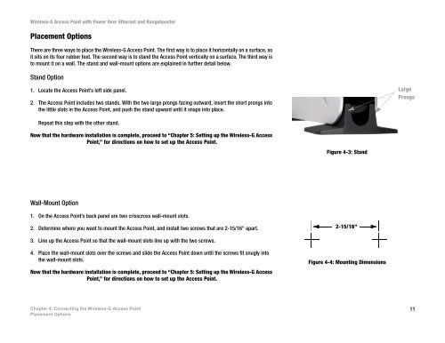
<strong>Wireless</strong>-G <strong>Access</strong> <strong>Point</strong> <strong>with</strong> Power Over Ethernet <strong>and</strong> RangeboosterPlacement OptionsThere are three ways to place the <strong>Wireless</strong>-G <strong>Access</strong> <strong>Point</strong>. The first way is to place it horizontally on a surface, soit sits on its four rubber feet. The second way is to st<strong>and</strong> the <strong>Access</strong> <strong>Point</strong> vertically on a surface. The third way isto mount it on a wall. The st<strong>and</strong> <strong>and</strong> wall-mount options are explained in further detail below.St<strong>and</strong> Option1. Locate the <strong>Access</strong> <strong>Point</strong>’s left side panel.2. The <strong>Access</strong> <strong>Point</strong> includes two st<strong>and</strong>s. With the two large prongs facing outward, insert the short prongs intothe little slots in the <strong>Access</strong> <strong>Point</strong>, <strong>and</strong> push the st<strong>and</strong> upward until it snaps into place.LargeProngsRepeat this step <strong>with</strong> the other st<strong>and</strong>.Now that the hardware installation is complete, proceed to “Chapter 5: Setting up the <strong>Wireless</strong>-G <strong>Access</strong><strong>Point</strong>,” for directions on how to set up the <strong>Access</strong> <strong>Point</strong>.Figure 4-3: St<strong>and</strong>Wall-Mount Option1. On the <strong>Access</strong> <strong>Point</strong>’s back panel are two crisscross wall-mount slots.2. Determine where you want to mount the <strong>Access</strong> <strong>Point</strong>, <strong>and</strong> install two screws that are 2-15/16" apart.2-15/16"3. Line up the <strong>Access</strong> <strong>Point</strong> so that the wall-mount slots line up <strong>with</strong> the two screws.4. Place the wall-mount slots over the screws <strong>and</strong> slide the <strong>Access</strong> <strong>Point</strong> down until the screws fit snugly intothe wall-mount slots.Now that the hardware installation is complete, proceed to “Chapter 5: Setting up the <strong>Wireless</strong>-G <strong>Access</strong><strong>Point</strong>,” for directions on how to set up the <strong>Access</strong> <strong>Point</strong>.Figure 4-4: Mounting DimensionsChapter 4: Connecting the <strong>Wireless</strong>-G <strong>Access</strong> <strong>Point</strong>Placement Options11