Cisco UCS C240 M3 High-Density Small Form Factor ... - Icecat.biz
Cisco UCS C240 M3 High-Density Small Form Factor ... - Icecat.biz
Cisco UCS C240 M3 High-Density Small Form Factor ... - Icecat.biz

Create successful ePaper yourself
Turn your PDF publications into a flip-book with our unique Google optimized e-Paper software.
<strong>Cisco</strong> <strong>UCS</strong> <strong>C240</strong> <strong>M3</strong><strong>High</strong>-<strong>Density</strong>Rack Server (<strong>Small</strong> <strong>Form</strong><strong>Factor</strong> Disk Drive Model)CISCO SYSTEMSPUBLICATION HISTORY170 WEST TASMAN DR.SAN JOSE, CA, 95134 REV B.1 NOVEMBER 8, 2012WWW.CISCO.COM
CONTENTSOVERVIEW . . . . . . . . . . . . . . . . . . . . . . . . . . . . . . . . . . . . . . . . . . . . . . . 3DETAILED VIEWS . . . . . . . . . . . . . . . . . . . . . . . . . . . . . . . . . . . . . . . . . . . 4Chassis Front View . . . . . . . . . . . . . . . . . . . . . . . . . . . . . . . . . . . . . . . . . . . . . . . . . . .4Chassis Rear View . . . . . . . . . . . . . . . . . . . . . . . . . . . . . . . . . . . . . . . . . . . . . . . . . . .5BASE SERVER STANDARD CAPABILITIES and FEATURES . . . . . . . . . . . . . . . . . 6CONFIGURING the SERVER . . . . . . . . . . . . . . . . . . . . . . . . . . . . . . . . . . . . 9STEP 1 VERIFY SERVER SKU . . . . . . . . . . . . . . . . . . . . . . . . . . . . . . . . . . . . . . . . . . . 10STEP 2 SELECT CPU(s) . . . . . . . . . . . . . . . . . . . . . . . . . . . . . . . . . . . . . . . . . . . . . . 11STEP 3 SELECT MEMORY . . . . . . . . . . . . . . . . . . . . . . . . . . . . . . . . . . . . . . . . . . . . . 13STEP 4 SELECT RAID CONFIGURATION . . . . . . . . . . . . . . . . . . . . . . . . . . . . . . . . . . . . 18STEP 5 SELECT HARD DISK DRIVES (HDDs) or SOLID STATE DRIVES (SSDs) . . . . . . . . . . . . . 23STEP 6 SELECT PCIe OPTION CARD(s) . . . . . . . . . . . . . . . . . . . . . . . . . . . . . . . . . . . . 25STEP 7 ORDER OPTIONAL NETWORK CARD ACCESSORIES . . . . . . . . . . . . . . . . . . . . . . . . 28STEP 8 ORDER POWER SUPPLY . . . . . . . . . . . . . . . . . . . . . . . . . . . . . . . . . . . . . . . . . 31STEP 9 SELECT AC POWER CORD(s) . . . . . . . . . . . . . . . . . . . . . . . . . . . . . . . . . . . . . 32STEP 10 ORDER OPTIONAL REVERSIBLE CABLE MANAGEMENT ARM . . . . . . . . . . . . . . . . . 35STEP 11 ORDER A TRUSTED PLATFORM MODULE . . . . . . . . . . . . . . . . . . . . . . . . . . . . . 36STEP 12 ORDER CISCO FLEXIBLE FLASH SD CARD MODULE (OPTIONAL) . . . . . . . . . . . . . . . 37STEP 13 ORDER OPTIONAL USB 2.0 DRIVE . . . . . . . . . . . . . . . . . . . . . . . . . . . . . . . . . 38STEP 14 SELECT OPERATING SYSTEM . . . . . . . . . . . . . . . . . . . . . . . . . . . . . . . . . . . . 39STEP 15 SELECT OPERATING SYSTEM MEDIA KIT . . . . . . . . . . . . . . . . . . . . . . . . . . . . . 41STEP 16 SELECT OPTIONAL VALUE-ADDED SOFTWARE . . . . . . . . . . . . . . . . . . . . . . . . . 42STEP 17 SELECT SERVICE and SUPPORT LEVEL . . . . . . . . . . . . . . . . . . . . . . . . . . . . . . 43OPTIONAL STEP - ORDER RACK(s) . . . . . . . . . . . . . . . . . . . . . . . . . . . . . . 47OPTIONAL STEP - ORDER PDU . . . . . . . . . . . . . . . . . . . . . . . . . . . . . . . . . 48SUPPLEMENTAL MATERIAL . . . . . . . . . . . . . . . . . . . . . . . . . . . . . . . . . . . 49CHASSIS . . . . . . . . . . . . . . . . . . . . . . . . . . . . . . . . . . . . . . . . . . . . . . . . . . . . . . . . . 49CPUs and DIMMs . . . . . . . . . . . . . . . . . . . . . . . . . . . . . . . . . . . . . . . . . . . . . . . . . . . . 50Physical Layout . . . . . . . . . . . . . . . . . . . . . . . . . . . . . . . . . . . . . . . . . . . . . . . . 50Memory Population Rules . . . . . . . . . . . . . . . . . . . . . . . . . . . . . . . . . . . . . . . . . 52Recommended Memory Configuration . . . . . . . . . . . . . . . . . . . . . . . . . . . . . . . . . 53Supported DIMM Populations . . . . . . . . . . . . . . . . . . . . . . . . . . . . . . . . . . . . . . . 55Low-Voltage DIMM Considerations . . . . . . . . . . . . . . . . . . . . . . . . . . . . . . . . . . . . 56RAID Summary . . . . . . . . . . . . . . . . . . . . . . . . . . . . . . . . . . . . . . . . . . . . . . . . . . . . . 56RACKS . . . . . . . . . . . . . . . . . . . . . . . . . . . . . . . . . . . . . . . . . . . . . . . . . . . . . . . . . . 58PDUs . . . . . . . . . . . . . . . . . . . . . . . . . . . . . . . . . . . . . . . . . . . . . . . . . . . . . . . . . . . 60KVM CABLE . . . . . . . . . . . . . . . . . . . . . . . . . . . . . . . . . . . . . . . . . . . . . . . . . . . . . . . 61Motherboard USB and SD Ports, and RAID Card Backup Locations . . . . . . . . . . . . . . . . . . . 62TECHNICAL SPECIFICATIONS . . . . . . . . . . . . . . . . . . . . . . . . . . . . . . . . . . 63Dimensions and Weight . . . . . . . . . . . . . . . . . . . . . . . . . . . . . . . . . . . . . . . . . . . . . . . 63Power Specifications . . . . . . . . . . . . . . . . . . . . . . . . . . . . . . . . . . . . . . . . . . . . . . . . 63Environmental Specifications . . . . . . . . . . . . . . . . . . . . . . . . . . . . . . . . . . . . . . . . . . . 65Compliance Requirements . . . . . . . . . . . . . . . . . . . . . . . . . . . . . . . . . . . . . . . . . . . . . 66<strong>Cisco</strong> <strong>UCS</strong> <strong>C240</strong> <strong>M3</strong> <strong>High</strong>-<strong>Density</strong> Rack Server (<strong>Small</strong> <strong>Form</strong> <strong>Factor</strong> Disk Drive Model) 2
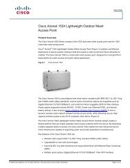
OVERVIEWOVERVIEWThe <strong>UCS</strong> <strong>C240</strong> <strong>M3</strong> rack server is designed for both performance and expandability over a wide range ofstorage-intensive infrastructure workloads from big data to collaboration.Building on the success of the <strong>Cisco</strong> <strong>UCS</strong> C210 M2 rack server, the enterprise-class <strong>UCS</strong> <strong>C240</strong> <strong>M3</strong> serverfurther extends the capabilities of <strong>Cisco</strong>’s Unified Computing System portfolio in a 2U form factor with theaddition of the Intel® E5-2600 series processor family CPUs that deliver the best combination ofperformance, flexibility and efficiency gains. In addition, the <strong>UCS</strong> <strong>C240</strong> <strong>M3</strong> server provides 24 DIMM slots, upto 24 drives and 4 x 1 GbE LOM to provide outstanding levels of internal memory and storage expandabilityalong with exceptional performance.Figure 1 <strong>Cisco</strong> <strong>UCS</strong> <strong>C240</strong> <strong>M3</strong> <strong>High</strong>-<strong>Density</strong> SFF Rack ServerFront ViewRear View<strong>Cisco</strong> <strong>UCS</strong> <strong>C240</strong> <strong>M3</strong> <strong>High</strong>-<strong>Density</strong> Rack Server (<strong>Small</strong> <strong>Form</strong> <strong>Factor</strong> Disk Drive Model)3
DETAILED VIEWSDETAILED VIEWSChassis Front ViewFigure 2 shows the <strong>Cisco</strong> <strong>UCS</strong> <strong>C240</strong> <strong>M3</strong> <strong>High</strong>-<strong>Density</strong> SFF Rack Server.Figure 2 Chassis Front View12HDD 1HDD 2HDD 3HDD 4HDD 5HDD 6HDD 7HDD 8HDD 9HDD 10HDD 11HDD 12HDD 13HDD 14HDD 15HDD 16HDD 17HDD 18HDD 19HDD 20HDD 21HDD 22HDD 23HDD 2446857310 93318071 KVM connector(used with KVM cable that provides two USB,one VGA, and one serial connector)6 Temperature status LED2 Asset tag (serial number) 7 Fan status LED3 Drives (up to 24 2.5-inch hot-swappabledrives)8 System status LED4 Network link activity LED 9 Identification button/LED5 Power supply status LED 10 Power button/power status LEDFor more information about the KVM cable connection, see KVM CABLE, page 61.4<strong>Cisco</strong> <strong>UCS</strong> <strong>C240</strong> <strong>M3</strong> <strong>High</strong>-<strong>Density</strong> Rack Server (<strong>Small</strong> <strong>Form</strong> <strong>Factor</strong> Disk Drive Model)
DETAILED VIEWSChassis Rear ViewFigure 3 shows the external features of the rear panel.Figure 3 Chassis Rear View12 3PSU1PSU2PCIe 5PCIe 4PCIe 1PCIe 2PCIe 34 5 6 7 8 9 10 113318261 Power supplies (up to two) 7 One RJ-45 10/100/1000 Ethernet dedicatedmanagement port2 Standard-profile PCIe slot on riser 2:PCIe 5—full-height, 3/4-length, x16 lanewidth, x24 connector, GPU ready3 Low-profile PCIe slot on riser:PCIe 4—half-height, 3/4-length, x8 lanewidth, x16 connector, no NCSI 2 support8 USB 2.0 port9 Quad 1-Gb Ethernet ports(LAN1, LAN2, LAN3, and LAN4)4 VGA video connector 10 Standard-profile PCIe slots on riser 1(three):PCIe 1—full-height, half-length, x8 lanewidth, x8 connectorPCIe 2—full-height, half-length, x16 lanewidth, x24 connector (supports <strong>Cisco</strong> VirtualInterface Card (VIC))PCIe 3—full-height, half-length, x8 lanewidth, x16 connector5 Serial connector (RJ-45) 11 Rear Identification button/LED6 USB 2.0 port -<strong>Cisco</strong> <strong>UCS</strong> <strong>C240</strong> <strong>M3</strong> <strong>High</strong>-<strong>Density</strong> Rack Server (<strong>Small</strong> <strong>Form</strong> <strong>Factor</strong> Disk Drive Model)5
BASE SERVER STANDARD CAPABILITIES and FEATURESBASE SERVER STANDARD CAPABILITIES and FEATURESTable 1 lists the capabilities and features of the base server. Details about how to configure the server fora particular feature or capability (for example, number of processors, disk drives, or amount of memory)are provided in CONFIGURING the SERVER, page 9.Table 1 Capabilities and FeaturesCapability/FeatureChassisCPUChipsetMemoryNICExpansion slotsInternal storage devices<strong>Cisco</strong> Flexible FlashdrivesDescriptionTwo rack unit (2RU) chassisOne or two Intel® E5-2600 series processor family CPUsIntel® C600 series chipset24 slots for registered ECC DIMMs (RDIMMs) or load-reduced DIMMs (LRDIMMs)Embedded dual-port Intel i350 PCIe-based Gigabit Ethernet controller,supporting the following:■ Pre-Execution Boot (PXE boot)■ iSCSI bootFive PCIe slots (on two riser cards)■ Riser 1 (PCIe slots 1, 2, and 3):• One x16 PCIe Gen3 Slot, x24 extended connector, full-height,half-length• Two x8 PCIe Gen3 Slots Full Height, x16 connector, half-length■ Riser 2 (PCIe slots 4 and 5):• One x16 PCIe Gen3 Slot, Full Height, (225W GPU Ready), x24connector, three-quarter length• One x8 PCIe Gen3 Slot, half-height, x16 connector, half-lengthDrives are installed into front-panel drive bays that provide hot-pluggableaccess.■ <strong>Small</strong> <strong>Form</strong> <strong>Factor</strong> (SFF) drives. The server can hold up to:• 24 2.5 inch (63.5 mm) SAS or SATA hard drives (HDDs) or solid statedrives (SSDs) (24-drive backplane with SAS expander configuration)• 16 2.5 inch (63.5 mm) SAS or SATA HDDs or SSDs (16-drive backplanewith no SAS expander configuration)■ The server also contains one internal USB 2.0 port on the motherboardthat you can use with a USB thumb drive for additional storageThe server supports one internal <strong>Cisco</strong> Flexible Flash drive (SD card).■The SD card is pre-loaded with four virtual drives. The four virtualdrives contain, respectively, the <strong>Cisco</strong> Server Configuration Utility, the<strong>Cisco</strong> Host Upgrade Utility, the <strong>Cisco</strong> C-Series server drivers set, and ablank virtual drive on which you can install an OS or a hypervisor.■ 4 GB is available for general use6<strong>Cisco</strong> <strong>UCS</strong> <strong>C240</strong> <strong>M3</strong> <strong>High</strong>-<strong>Density</strong> Rack Server (<strong>Small</strong> <strong>Form</strong> <strong>Factor</strong> Disk Drive Model)
BASE SERVER STANDARD CAPABILITIES and FEATURESCapability/FeatureDescriptionStorage controller ■ Embedded RAID (3 Gbs)• Embedded SATA-only RAID controller, supporting up to four SATA-onlydrives (RAID 0, 1, 10)• ROM5 RAID upgrade, supporting up to eight SAS/SATA HDDs or SSDs(RAID 0, 1, 10). SAS and SATA drives can be mixed.• ROM55 RAID upgrade, supporting up to eight SAS/SATA HDDs or SSDs(RAID 0, 1, 10, 5). SAS and SATA drives can be mixed.Note that embedded RAID options can be supported only with the version ofthe <strong>C240</strong> <strong>M3</strong> SFF server that has been configured with a 16-drive backplanewith no SAS expander.■Mezzanine Cards (6 Gbs) - two versions• <strong>Cisco</strong> <strong>UCS</strong>C RAID SAS 2008M-8i Mezzanine Card supports up to 8 or 16SAS/SATA drives (depending on the backplane used) supporting RAID0, 1, 10, 5, and 50. SAS and SATA drives can be mixed. This card has aproduct ID (PID) of <strong>UCS</strong>C-RAID-11-<strong>C240</strong>.• <strong>Cisco</strong> <strong>UCS</strong>C RAID SAS 2008M-8i Mezzanine Card supports up to 8 or 16SAS/SATA drives (depending on the backplane used) supporting RAID0, 1, and 10. SAS and SATA drives can be mixed. This card has aproduct ID (PID) of <strong>UCS</strong>C-RAID-MZ-240.Note that mezzanine cards are used as follows:■• A mezzanine card in a 16-drive backplane system with no SASexpander can support up to 8 drives.• A mezzanine card in a 24-drive backplane system with SAS expandercan support up to 16 drives.Plug-in PCIe Cards (6 Gbs)• LSI MegaRAID SAS 9266-8i 8-port plug-in PCIe RAID RAID controllercard (occupies a half-height PCIe slot) supporting RAID levels 0, 1,10, 5, 6, 50, 60 and up to 24 internal SAS or SATA drives (with24-drive backplane with SAS expander). SAS and SATA drives can bemixed.• LSI MegaRAID SAS 9266CV-8i RAID 8-port PCIe plug-in RAID controllercard, supporting RAID 0, 1, 10, 5, 6, 50, and 60 and up to up to 24internal SAS or SATA drives (with 24-drive backplane with SASexpander). SAS and SATA drives can be mixed.VideoThe Emulex Pilot 3 Integrated Baseboard Management Controller providesvideo:■ Matrox G200e video controller■ Integrated 2D graphics core with hardware acceleration■ Supports all display resolutions up to 1920 x 1200 x 16 bpp resolution at60 Hz■ 24-bit color depth for all resolutions less than 1600x1200■ Up to 256 MB video memory<strong>Cisco</strong> <strong>UCS</strong> <strong>C240</strong> <strong>M3</strong> <strong>High</strong>-<strong>Density</strong> Rack Server (<strong>Small</strong> <strong>Form</strong> <strong>Factor</strong> Disk Drive Model)7
BASE SERVER STANDARD CAPABILITIES and FEATURESCapability/FeatureInterfacesDescriptionRear panel■■■■■■One RJ-45 10/100/1000 Ethernet management port, using <strong>Cisco</strong>Integrated Management Controller (CIMC) firmwareFour 1-Gb LOM portsOne RJ45 serial port connectorTwo USB 2.0 port connectorsOne DB15 VGA connectorVarious PCIe card ports (dependent on which cards are installed)• Converged Network Adapter (CNA) ports• Network Interface Card (NIC) ports• Host Bus Adapter (HBA) portsFront panel■ One KVM console connector (supplies two USB 2.0, one VGA, and oneserial connector)Front Panel ■ A front panel controller provides status indications and control buttonsPower subsystemFansIntegrated managementprocessorOne power supply is required (either 650 W or 1200 W). An additional powersupply may be ordered to provide 1+1 redundancy. The power supplies mustmatch in a redundant power supply configuration.Chassis:■ Six hot-swappable fans for front-to-rear coolingPower supply:■Each power supply is equipped with a fan.<strong>Cisco</strong> Integrated Management Controller (CIMC) firmware.Depending on your CIMC settings, the CIMC can be accessed through the 1-GbEthernet dedicated management port, the 1-Gb Ethernet LOM ports, or a<strong>Cisco</strong> P81E or <strong>Cisco</strong> 1225 virtual interface card (VIC).8<strong>Cisco</strong> <strong>UCS</strong> <strong>C240</strong> <strong>M3</strong> <strong>High</strong>-<strong>Density</strong> Rack Server (<strong>Small</strong> <strong>Form</strong> <strong>Factor</strong> Disk Drive Model)
CONFIGURING the SERVERCONFIGURING the SERVERFollow these steps to configure the <strong>Cisco</strong> <strong>UCS</strong> <strong>C240</strong> <strong>M3</strong> <strong>High</strong>-<strong>Density</strong> SFF Rack Server:■ STEP 1 VERIFY SERVER SKU, page 10■ STEP 2 SELECT CPU(s), page 11■ STEP 3 SELECT MEMORY, page 13■ STEP 4 SELECT RAID CONFIGURATION, page 18■ STEP 5 SELECT HARD DISK DRIVES (HDDs) or SOLID STATE DRIVES (SSDs), page 23■ STEP 6 SELECT PCIe OPTION CARD(s), page 25■ STEP 7 ORDER OPTIONAL NETWORK CARD ACCESSORIES, page 28■ STEP 8 ORDER POWER SUPPLY, page 31■ STEP 9 SELECT AC POWER CORD(s), page 32■ STEP 10 ORDER OPTIONAL REVERSIBLE CABLE MANAGEMENT ARM, page 35■ STEP 11 ORDER A TRUSTED PLATFORM MODULE, page 36■ STEP 12 ORDER CISCO FLEXIBLE FLASH SD CARD MODULE (OPTIONAL), page 37■ STEP 13 ORDER OPTIONAL USB 2.0 DRIVE, page 38■ STEP 14 SELECT OPERATING SYSTEM, page 39■ STEP 15 SELECT OPERATING SYSTEM MEDIA KIT, page 41■ STEP 16 SELECT OPTIONAL VALUE-ADDED SOFTWARE, page 42■ STEP 17 SELECT SERVICE and SUPPORT LEVEL, page 43■ OPTIONAL STEP - ORDER RACK(s), page 47■ OPTIONAL STEP - ORDER PDU, page 48<strong>Cisco</strong> <strong>UCS</strong> <strong>C240</strong> <strong>M3</strong> <strong>High</strong>-<strong>Density</strong> Rack Server (<strong>Small</strong> <strong>Form</strong> <strong>Factor</strong> Disk Drive Model)9
CONFIGURING the SERVERSTEP 1VERIFY SERVER SKUSelect one server product ID (PID) from Table 2.Table 2 PID of the <strong>C240</strong> <strong>M3</strong> <strong>High</strong>-<strong>Density</strong> SFF Rack Base ServerProduct ID (PID)<strong>UCS</strong>C-<strong>C240</strong>-<strong>M3</strong>S2<strong>UCS</strong>C-<strong>C240</strong>-<strong>M3</strong>SDescription<strong>UCS</strong> <strong>C240</strong> <strong>M3</strong> SFF, no CPU, memory, HDD, power supply, or PCIe, with rail kit,16-drive backplane, and no SAS expander<strong>UCS</strong> <strong>C240</strong> <strong>M3</strong> SFF, no CPU, memory, HDD, power supply, or PCIe, with rail kit,24-drive backplane, and SAS expanderThe <strong>Cisco</strong> <strong>C240</strong> <strong>M3</strong> server:■■Includes one tool-less rail kit, adjustable from 26 inches (660 mm) to 36 inches (914 mm)Includes either a 24- or 16-drive backplane.NOTE: Embedded RAID can only be used with systems implementing a16-drive backplane that contains no SAS expander.Mezzanine cards can be used as follows:■ A mezzanine card in a 16-drive backplane system with no SASexpander can support up to 8 drives.■ A mezzanine card in a 24-drive backplane system with SAS expandercan support up to 16 drives.■Does not include power supply, CPU, memory, hard disk drives (HDDs), solid-state drives(SSDs), SD card, or plug-in PCIe cards.NOTE: Use the steps on the following pages to configure the server withthe components that you want to include.10<strong>Cisco</strong> <strong>UCS</strong> <strong>C240</strong> <strong>M3</strong> <strong>High</strong>-<strong>Density</strong> Rack Server (<strong>Small</strong> <strong>Form</strong> <strong>Factor</strong> Disk Drive Model)
CONFIGURING the SERVERSTEP 2SELECT CPU(s)The standard CPU features are:■■■Intel E5-2600 series processor family CPUIntel® C600 series chipsetCache size of 10, 15, or 20 MBSelect CPUsThe available CPUs are listed in Table 3.Table 3 Available Intel CPUs: E5-2600 Series Processor Family CPUsProduct ID (PID)IntelNumberClockFreq(GHz)Power(W)CacheSize(MB)CoresQPI<strong>High</strong>est DDR3DIMM ClockSupport (MHz) 1<strong>UCS</strong>-CPU-E5-2690 E5-2690 2.90 135 20 8 8 GT/s 1600<strong>UCS</strong>-CPU-E5-2680 E5-2680 2.70 130 20 8 8 GT/s 1600<strong>UCS</strong>-CPU-E5-2670 E5-2670 2.60 115 20 8 8 GT/s 1600<strong>UCS</strong>-CPU-E5-2667 E5-2667 2.90 130 15 6 8 GT/s 1600<strong>UCS</strong>-CPU-E5-2665 E5-2665 2.40 115 20 8 8 GT/s 1600<strong>UCS</strong>-CPU-E5-2660 E5-2660 2.20 95 20 8 8 GT/s 1600<strong>UCS</strong>-CPU-E5-2650 E5-2650 2.00 95 20 8 8 GT/s 1600<strong>UCS</strong>-CPU-E5-2650L E5-2650L 1.80 70 20 8 8 GT/s 1600<strong>UCS</strong>-CPU-E5-2643 E5-2643 3.30 130 10 4 8 GT/s 1600<strong>UCS</strong>-CPU-E5-2640 E5-2640 2.50 95 15 6 7.2 GT/s 1333<strong>UCS</strong>-CPU-E5-2630 E5-2630 2.30 95 15 6 7.2 GT/s 1333<strong>UCS</strong>-CPU-E5-2630L E5-2630L 2.00 60 15 6 7.2 GT/s 1333<strong>UCS</strong>-CPU-E5-2620 E5-2620 2.00 95 15 6 7.2 GT/s 1333<strong>UCS</strong>-CPU-E5-2609 E5-2609 2.40 80 10 4 6.4 GT/s 1066Notes . . .1. If higher or lower speed DIMMs are selected than what is shown in the table for a given CPU, the DIMMs will beclocked at the lowest common denominator of CPU clock and DIMM clock.<strong>Cisco</strong> <strong>UCS</strong> <strong>C240</strong> <strong>M3</strong> <strong>High</strong>-<strong>Density</strong> Rack Server (<strong>Small</strong> <strong>Form</strong> <strong>Factor</strong> Disk Drive Model)11
CONFIGURING the SERVERApproved Configurations(1) 1-CPU configurations:■ Select any one CPU listed in Table 3.(2) 2-CPU Configurations:■ Select two identical CPUs from any one of the rows of Table 3 on page 11.Caveats■■You can select either one processor or two identical processors.For optimal performance, select DIMMs with the highest clock speed for a given processor(see Table 3 on page 11). If you select DIMMs whose speeds are lower or higher than thatshown in the tables, suboptimal performance will result.12<strong>Cisco</strong> <strong>UCS</strong> <strong>C240</strong> <strong>M3</strong> <strong>High</strong>-<strong>Density</strong> Rack Server (<strong>Small</strong> <strong>Form</strong> <strong>Factor</strong> Disk Drive Model)
CONFIGURING the SERVERSTEP 3SELECT MEMORYThe standard memory features are:■■DIMMs— Clock speed: 1333 or 1600 MHz— Ranks per DIMM: 1, 2, or 4— Operational voltage: dual voltage capable (1.5 V or 1.35 V)— Registered ECC DDR3 DIMMS (RDIMMS) or load-reduced DIMMS (LRDIMMs)Memory is organized with four memory channels per CPU, with up to three DIMMs perchannel, as shown in Figure 4.Figure 4 <strong>C240</strong> <strong>M3</strong> SFF Memory Organization<strong>Cisco</strong> <strong>UCS</strong> <strong>C240</strong> <strong>M3</strong> <strong>High</strong>-<strong>Density</strong> Rack Server (<strong>Small</strong> <strong>Form</strong> <strong>Factor</strong> Disk Drive Model)13
CONFIGURING the SERVERSelect DIMMs and Memory MirroringSelect the memory configuration and whether or not you want the memory mirroring option.The available memory DIMMs and mirroring option are listed in Table 4.NOTE: When memory mirroring is enabled, the memory subsystem simultaneouslywrites identical data to two channels. If a memory read from one of the channelsreturns incorrect data due to an uncorrectable memory error, the systemautomatically retrieves the data from the other channel. A transient or soft error inone channel does not affect the mirrored data, and operation continues unless thereis a simultaneous error in exactly the same location on a DIMM and its mirroredDIMM. Memory mirroring reduces the amount of memory available to the operatingsystem by 50% because only one of the two populated channels provides data.Table 4 Available DDR3 DIMMsProduct ID (PID) PID Description VoltageRanks/DIMMDIMM Options<strong>UCS</strong>-ML-1X324RY-A 32GB DDR3-1600-MHz LR DIMM/PC3-12800/quad rank/x4/1.35v 1.35 V 4<strong>UCS</strong>-MR-1X162RY-A 16GB DDR3-1600-MHz RDIMM/PC3-12800/dual rank/x4/1.35v 1.35 V 2<strong>UCS</strong>-MR-1X162RX-A 16GB DDR3-1333-MHz RDIMM/PC3-10600/dual rank/x4/1.35v 1.35 V 2<strong>UCS</strong>-MR-1X082RY-A 8GB DDR3-1600-MHz RDIMM/PC3-12800/dual rank/x4/1.35v 1.35 V 2<strong>UCS</strong>-MR-1X082RX-A 8GB DDR3-1333-MHz RDIMM/PC3-10600/dual rank/x4/1.35v 1.35 V 2<strong>UCS</strong>-MR-1X041RY-A 4GB DDR3-1600-MHz RDIMM/PC3-12800/single rank/x4/1.35v 1.35 V 1<strong>UCS</strong>-MR-1X041RX-A 4GB DDR3-1333-MHz RDIMM/PC3-10600/single rank/x4/1.35v 1.35 V 1Memory Mirroring OptionN01-MMIRRORMemory mirroring optionApproved Configurations(1) 1-CPU configuration without memory mirroring:■Select from 1 to 12 DIMMs. Refer to Memory Population Rules, page 52, for more detailedinformation.(2) 1-CPU configuration with memory mirroring:14<strong>Cisco</strong> <strong>UCS</strong> <strong>C240</strong> <strong>M3</strong> <strong>High</strong>-<strong>Density</strong> Rack Server (<strong>Small</strong> <strong>Form</strong> <strong>Factor</strong> Disk Drive Model)
CONFIGURING the SERVER■Select 2, 4, 6, 8, 10, or 12 identical DIMMs. The DIMMs will be placed by the factory as shownin the following table.TotalNumberofDIMMsBlue Slot(Slot 1)CPU 1 DIMM Placement in Channels(for identical DIMMs)Black Slot(Slot 2)Black Slots(Slot 3)2 (A1, B1) — —4 (A1,B1); (C1,D1) — —6 (A1,B1); (C1,D1) (A2,B2) —8 (A1,B1); (C1,D1) (A2,B2); (C2,D2) —10 1(A1,B1); (C1,D1) (A2,B2); (C2,D2) (A3,B3)12 1 (A1,B1); (C1,D1) (A2,B2); (C2,D2) (A3,B3); (C3,D3)Notes . . .1. This configuration cannot be implemented with quad-rank DIMMs (the 32 GB DIMM). You can haveonly 1 or 2 DIMMs per channel when using quad-rank DIMMs.■ Select the memory mirroring option (N01-MMIRROR) as shown in Table 4 on page 14.(3) 2-CPU configuration without memory mirroring:■Select from 1 to 12 DIMMs per CPU. Refer to Memory Population Rules, page 52, for moredetailed information.<strong>Cisco</strong> <strong>UCS</strong> <strong>C240</strong> <strong>M3</strong> <strong>High</strong>-<strong>Density</strong> Rack Server (<strong>Small</strong> <strong>Form</strong> <strong>Factor</strong> Disk Drive Model)15
CONFIGURING the SERVER(4) 2-CPU configuration with memory mirroring:■Select 2, 4, 6, 8, 10, or 12 identical DIMMs per CPU. The DIMMs will be placed by the factoryas shown in the following table.NumberofDIMMsper CPUCPU 1 DIMM Placement in Channels(for identical DIMMs)CPU 2 DIMM Placement in Channels(for identical DIMMs)Blue Slots Black Slots Black Slots Blue Slots Black Slots Black Slots2 (A1, B1) (E1, F1)4 (A1,B1);(C1,D1)6 (A1,B1);(C1,D1)— — (E1,F1);(G1,H1)(A2,B2) — (E1,F1);(G1,H1)— —(E2,F2) —8 (A1,B1);(C1,D1)(A2,B2);(C2,D2)— (E1,F1);(G1,H1)(E2,F2);(G2,H2)—10 1(A1,B1);(C1,D1)(A2,B2);(C2,D2)(A3,B3)(E1,F1);(G1,H1)(E2,F2);(G2,H2)(E3,F3)12 1 (A1,B1);(C1,D1)(A2,B2);(C2,D2)(A3,B3);(C3,D3)(E1,F1);(G1,H1)(E2,F2);(G2,H2)(E3,F3);(G3,H3)Notes . . .1. This configuration cannot be implemented with quad-rank DIMMs (the 32 GB DIMM). You can have only 1 or 2DIMMs per channel when using quad-rank DIMMs.■ Select the memory mirroring option (N01-MMIRROR) as shown in Table 4 on page 14.NOTE: System performance is optimized when the DIMM type and quantity are equalfor both CPUs.16<strong>Cisco</strong> <strong>UCS</strong> <strong>C240</strong> <strong>M3</strong> <strong>High</strong>-<strong>Density</strong> Rack Server (<strong>Small</strong> <strong>Form</strong> <strong>Factor</strong> Disk Drive Model)
CONFIGURING the SERVERCaveats■■■■■■■■■The server supports 1, 2, or 3 DIMMs per channel for single- or dual-rank RDIMMs.The server supports 1, 2, or 3 DIMMs per channel for quad-rank LRDIMMs.The server supports registered DIMMs (RDIMMs) or load-reduced DIMMS (LRDIMMs), however,do not mix RDIMMs and LRDIMMs in a server.When using mirroring, DIMMs must be installed in identical pairs across paired DDR3 buses.That is, mirrored pairs in channels A and B must be identical and pairs in channels C and Dmust be identical. However, the DIMMs used in channels A and B and in C and D can bedifferent.UDIMMs and non-ECC DIMMs are not supported.Memory mirroring reduces the amount of available memory by 50% (quantity of DIMMs mustbe even for mirroring).When single- and dual-rank DIMMs are populated for 2DPC, always populate the dual-rankDIMM in the blue DIMM slot first (blue slot) and the single-rank DIMM last in the black DIMMslots (only the 4GB DIMMs are single-rank).By default, all DIMMs run at 1.35 V, which yields 1333-MHz memory speeds. To run thememory DIMMS at 1600 MHz, you need to go into the BIOS or set the policy with <strong>UCS</strong>M(service profile) to run in Performance Mode. This forces the DIMMs to operate at 1.5 V andyields 1600-MHz speeds, provided:— The DIMMs are 1600-MHz devices and the DIMM type is RDIMM— The CPUs chosen support 1600-MHz operation— There are less than 3 DIMMs per channelWith 3 DIMMs populated per channel, memory always runs at 1.5 V regardless if the BIOSsetting is low-power mode (1.35 V) or performance mode (1.5 V).NOTE: Memory speed is limited to 1066 MHz for 3 DPC configurations.NOTE: 32 GB LRDIMMs run at a maximum speed of 1333 MHz for 1DPC and 2DPC eventhough their specified maximum speed is 1600 MHz.For more information regarding memory, see CPUs and DIMMs, page 50.<strong>Cisco</strong> <strong>UCS</strong> <strong>C240</strong> <strong>M3</strong> <strong>High</strong>-<strong>Density</strong> Rack Server (<strong>Small</strong> <strong>Form</strong> <strong>Factor</strong> Disk Drive Model)17
CONFIGURING the SERVERSTEP 4SELECT RAID CONFIGURATIONThe RAID controller choices are:■Embedded RAID (on motherboard)NOTE: If you do not select a mezzanine card, a plug-in PCIe RAID card, or one of theembedded RAID upgrade options, you will have an embedded SATA-only RAIDcontroller that supports up to four SATA-only drives (RAID 0, 1, 10)■■Mezzanine RAID controller cardsPlug-in PCIe RAID controller cards<strong>Cisco</strong> can provide factory-configured RAID systems depending on the RAID controller chosen andthe number of drives ordered. <strong>Factor</strong>y-configured RAID options are listed with each RAID carddescription.NOTE: The number of RAID groups (logical drives/virtual drives) supported percontroller is as follows:■ Embedded RAID = 8 drives■ <strong>Cisco</strong> <strong>UCS</strong>C RAID SAS 2008M-8i Mezzanine Card = 16 drives■ LSI MegaRAID SAS 9266-8i/9266CV-8i RAID controller cards = 64 drivesSelect RAID OptionsSelect as follows:■ One embedded RAID upgrade option (see Table 5), or■ One mezzanine RAID controller (see Table 6), or■ One PCIe RAID controller card (see Table 7 on page 19)Table 5 Available Embedded RAID OptionsProduct ID (PID)PID DescriptionRAID Controllers<strong>UCS</strong>C-RAID-ROM5<strong>UCS</strong>C-RAID-ROM55Onboard RAID, supporting up to 8 SAS or SATA drives. SAS and SATA drives canbe mixed. This option supports RAID 0, 1, and 10, and operates at 3 Gb/s.Operating systems supported are Windows and Linux only (no VMwaresupport).Onboard RAID, supporting up to 8 SAS or SATA drives. SAS and SATA drives canbe mixed. This option supports RAID 0, 1, 10, and 5, and operates at 3 Gb/s.Operating systems supported are Windows and Linux only (no VMwaresupport).18<strong>Cisco</strong> <strong>UCS</strong> <strong>C240</strong> <strong>M3</strong> <strong>High</strong>-<strong>Density</strong> Rack Server (<strong>Small</strong> <strong>Form</strong> <strong>Factor</strong> Disk Drive Model)
CONFIGURING the SERVERTable 6 Available Mezzanine Card RAID OptionsProduct ID (PID)PID DescriptionRAID Controllers<strong>UCS</strong>C-RAID-11-<strong>C240</strong> <strong>Cisco</strong> <strong>UCS</strong>C RAID SAS 2008M-8i Mezzanine Card (RAID 0, 1, 10, 5, and 50supported), operating at 6 Gbs.■ Supports up to 8 or 16 internal SAS or SATA drives (depending on thebackplane size). SAS and SATA drives can be mixed.■ <strong>Factor</strong>y-configured RAID options available: RAID 0, 1, 10, and 5 (see theRAID PIDs section in this table)■ No data cache backup<strong>UCS</strong>C-RAID-MZ-240<strong>Cisco</strong> <strong>UCS</strong>C RAID SAS 2008M-8i Mezzanine Card (RAID 0, 1, 10 supported),operating at 6 Gbs.■ Supports up to 8 or 16 internal SAS or SATA drives (depending on thebackplane size). SAS and SATA drives can be mixed.■ <strong>Factor</strong>y-configured RAID options available: RAID 0, 1, and 10 (see the RAIDPIDs section in this table)■ No data cache backupTable 7 Available Plug-In PCIe Card RAID OptionsProduct ID (PID)PID DescriptionRAID Controllers<strong>UCS</strong>-RAID-9266NB<strong>UCS</strong>-RAID-9266CVLSI MegaRAID SAS 9266-8i RAID controller card with no data cache backup(RAID 0, 1, 10, 5, 6, 50, and 60 supported), operating at 6 Gbs.■ Installed by default in the half-height PCIe slot (slot 2)■■■Supports up to 24 internal SAS and/or SATA drives. SAS and SATA drives canbe mixed.Includes 1 GB of write cache<strong>Factor</strong>y-configured RAID options available: RAID 0, 1, 10, 5, and 6 (see theRAID PIDs section in this table)LSI MegaRAID SAS 9266CV-8i RAID controller card with data cache backup (RAID0, 1, 10, 5, 6, 50, 60), operating at 6 Gbs.■ Supports up to 24 internal SAS or SATA drives. SAS and SATA drives can bemixed.■ Includes a 1 GB Transportable Memory Module (TMM) and SuperCap powermodule for data cache backup■ <strong>Factor</strong>y-configured RAID options available: RAID 0, 1, 10, 5, and 6 (see theRAID PIDs section in this table)Super Capacitor Option<strong>UCS</strong>-RAID-CV-SC=LSI CacheVault Power Module for SAS 9266CV-8i<strong>Cisco</strong> <strong>UCS</strong> <strong>C240</strong> <strong>M3</strong> <strong>High</strong>-<strong>Density</strong> Rack Server (<strong>Small</strong> <strong>Form</strong> <strong>Factor</strong> Disk Drive Model)19
CONFIGURING the SERVERTable 7 Available Plug-In PCIe Card RAID Options (continued)Product ID (PID)PID DescriptionRAID Configuration OptionsR2XX-RAID0R2XX-RAID1R2XX-RAID5R2XX-RAID6R2XX-RAID10<strong>Factor</strong>y preconfigured RAID striping optionEnable RAID 0 Setting. Requires a minimum of one hard drive.<strong>Factor</strong>y preconfigured RAID mirroring optionEnable RAID 1 Setting. Requires exactly two drives with the same size, speed,capacity.<strong>Factor</strong>y preconfigured RAID optionEnable RAID 5 Setting. Requires a minimum of three drives of the same size,speed, capacity.<strong>Factor</strong>y preconfigured RAID optionEnable RAID 6 Setting. Requires a minimum of four drives of the same size,speed, capacity.<strong>Factor</strong>y preconfigured RAID optionEnable RAID 10 Setting. Requires a even number of drives (minimum of fourdrives) of the same size, speed, capacity.NOTE: Although RAID levels 50 and 60 are not orderable from the factory, they aresupported for selected controllers as shown in Table 5NOTE: No RAID option can be chosen if you have no drives20<strong>Cisco</strong> <strong>UCS</strong> <strong>C240</strong> <strong>M3</strong> <strong>High</strong>-<strong>Density</strong> Rack Server (<strong>Small</strong> <strong>Form</strong> <strong>Factor</strong> Disk Drive Model)
CONFIGURING the SERVERApproved Configurations(1) 1-CPU ConfigurationsMezzanine cards are not supported for 1-CPU configurations, Therefore, only the following RAIDcontrollers are supported for single-CPU configurations:■Embedded RAID (on motherboard)■ LSI MegaRAID SAS 9266-8i■LSI MegaRAID SAS 9266CV-8i(2) 2-CPU ConfigurationsCaveatsSelect an embedded RAID option from Table 5, one mezzanine RAID controller from Table 6 onpage 19, or one PCIe RAID controller from Table 7 on page 19. You may also select anappropriate optional RAID configuration listed in Table 7 on page 19.■■■■■■■The mezzanine controller is not available for 1-CPU configurations.If you choose embedded RAID or a mezzanine card RAID controller, all five of the PCIe cardslots are still available for adding optional PCIe cards.The optional PCIe RAID controllers are all half-height PCIe cards. If you choose one of thesecards, four PCIe card slots will be available for adding an optional PCIe card.Note that when just one CPU is populated, only a single <strong>Cisco</strong> <strong>UCS</strong> P81E or <strong>Cisco</strong> 1225 VirtualInterface Card (VIC) card is supported and it must be installed in the full-height PCIe slot(slot 2) on riser 1. So take this into account when populating RAID controller cards. Whentwo CPUs are populated, two VIC cards are supported (either the <strong>Cisco</strong> <strong>UCS</strong> P81E or <strong>Cisco</strong>VIC 1225 or both). One can be installed in slot 2 of riser 1 and one in slot 5 of riser 2. Theprimary slot for a VIC card is slot 2. If you have only one of these cards, install it in slot 2.You can choose only one RAID controller (embedded RAID, mezzanine RAID, or a plug-in PCIeRAID controller).You can choose an optional RAID configuration (RAID 0, 1, 5, 6, or 10), which ispreconfigured at the factory. The RAID level you choose must be an available RAID choice forthe controller selected. RAID levels 50 and 60 are supported, although they are not availableas configuration options.RAID support is dependent on the backplane:— A system with 16-drive backplane with no SAS expander:• Supports up to 8 drives with ROM5 and ROM55 embedded RAID upgrades• Supports up to 8 drives with mezzanine cards• Supports up to 8 drives for each SAS 9266-8i and SAS 9266CV-8i controller• Supports up to 4 SATA-only drives if no ROM upgrade, mezzanine card, or plug-inPCIe card chosen— A system with 24-drive backplane with SAS expander:<strong>Cisco</strong> <strong>UCS</strong> <strong>C240</strong> <strong>M3</strong> <strong>High</strong>-<strong>Density</strong> Rack Server (<strong>Small</strong> <strong>Form</strong> <strong>Factor</strong> Disk Drive Model)21
CONFIGURING the SERVER• Does not support ROM5 and ROM55 embedded RAID upgrades• Supports up to 16 drives with mezzanine cards• Supports up to 24 drives with SAS 9266-8i and SAS 9266CV-8i controllers• Supports up to 4 SATA-only drives if no ROM upgrade, mezzanine card, or plug-inPCIe card chosen22<strong>Cisco</strong> <strong>UCS</strong> <strong>C240</strong> <strong>M3</strong> <strong>High</strong>-<strong>Density</strong> Rack Server (<strong>Small</strong> <strong>Form</strong> <strong>Factor</strong> Disk Drive Model)
CONFIGURING the SERVERSTEP 5(SSDs)SELECT HARD DISK DRIVES (HDDs) or SOLID STATE DRIVESThe standard disk drive features are:■■■2.5-inch small form factorHot-pluggableSled-mountedSelect DrivesThe available drives are listed in Table 8.Table 8 Available Hot-Pluggable Sled-Mounted HDDs and SSDsProduct ID (PID)PID DescriptionDriveTypeCapacityHDDsA03-D1TBSATA 1 TB SATA 7.2K RPM SFF HDD SATA 1 TB<strong>UCS</strong>-HDD900GI2F106 900 GB 6Gb SAS 10K RPM SFF HDD SAS 900 GBA03-D600GA2 600 GB 6Gb SAS 10K RPM SFF HDD SAS 600 GBA03-D500GC3 500 GB SATA 7.2K RPM SFF HDD SATA 500 GB<strong>UCS</strong>-HDD300GI2F105 300 GB 6Gb SAS 15K RPM SFF HDD SAS 300 GBA03-D300GA2 300 GB 6Gb SAS 10K RPM SFF HDD SAS 300 GBA03-D146GC2 146 GB 6Gb SAS 15K RPM SFF HDD SAS 146 GBSSDs<strong>UCS</strong>-SD300G0KA2-E 300GB Std Height 15mm SATA SSD SATA 300 GB<strong>UCS</strong>-SD200G0KA2-E 200GB Std Height 15mm SATA SSD SATA 200 GB<strong>UCS</strong>-SD100G0KA2-E 100GB Std Height 15mm SATA SSD SATA 100 GBNOTE: No RAID option can be chosen if you have no drivesNOTE: No virtual drive groupings are allowed if you mix HDDs and SSDs.<strong>Cisco</strong> <strong>UCS</strong> <strong>C240</strong> <strong>M3</strong> <strong>High</strong>-<strong>Density</strong> Rack Server (<strong>Small</strong> <strong>Form</strong> <strong>Factor</strong> Disk Drive Model)23
CONFIGURING the SERVERApproved Configurations(1) Onboard RAID, Mezzanine Cards, and all Plug-In RAID Controllers■■■If you have not selected an onboard RAID upgrade option (ROM5 or ROM55), a mezzaninecard, or a plug-in RAID controller for internal drives (LSI MegaRAID SAS 9266-8i or LSIMegaRAID SAS 9266CV-8i), you may select up to 4 SATA-only drives from Table 8.For systems with a 16-drive backplane with no SAS expander:— Select up to 8 drives for ROM5 or ROM55 embedded RAID upgrade or a mezzaninecard.— Select up to 16 drives for SAS 9266-8i or SAS 9266CV-8i controllers.For systems with a 24-drive backplane with SAS expander:— If you selected a ROM5 or ROM55 embedded RAID upgrade, no drives are supported.— Select up to 16 drives for mezzanine cards.— Select up to 24 drives for SAS 9266-8i or SAS 9266CV-8i controllersCaveats■You can mix SATA and SAS drives.24<strong>Cisco</strong> <strong>UCS</strong> <strong>C240</strong> <strong>M3</strong> <strong>High</strong>-<strong>Density</strong> Rack Server (<strong>Small</strong> <strong>Form</strong> <strong>Factor</strong> Disk Drive Model)
CONFIGURING the SERVERSTEP 6SELECT PCIe OPTION CARD(s)The standard PCie card offerings are:■■■Converged Network Adapters (CNAs)Network Interface Cards (NICs)Host Bus Adapters (HBAs)Select PCIe Option CardsThe available PCIe option cards are listed in Table 9.Table 9 Available PCIe Option CardsProduct ID (PID)PID DescriptionCardHeightConverged Network Adapters (CNAs)N2XX-ACPCI01 <strong>Cisco</strong> <strong>UCS</strong> P81E Virtual Interface Card (VIC)/ 2-port 10Gbps Full<strong>UCS</strong>C-PCIE-BSFP Broadcom 57712 Dual Port 10Gb SFP+ w/TOE iSCSI Half<strong>UCS</strong>C-PCIE-CSC-02 <strong>Cisco</strong> VIC 1225 Dual Port 10Gb SFP+ CNA HalfNetwork Interface Cards (NICs)N2XX-ABPCI01-<strong>M3</strong> Broadcom 5709 Dual Port 1Gb w/TOE iSCSI for <strong>M3</strong> Servers HalfN2XX-ABPCI03-<strong>M3</strong> Broadcom 5709 Quad Port 1Gb w/TOE iSCSI for <strong>M3</strong> Servers HalfN2XX-AIPCI01 Intel X520 Dual Port 10Gb SFP+ Adapter Half<strong>UCS</strong>C-PCIE-IRJ45 Intel i350 Quad Port 1Gb Adapter Half<strong>UCS</strong>C-PCIE-BTG Broadcom 57712 Dual Port 10GBASE-T w/TOE iSCSI HalfHost Bus Adapters (HBAs)N2XX-AEPCI03 Emulex LPe 11002 Dual Port 4Gb Fibre Channel HBA HalfN2XX-AEPCI05 Emulex LPe 12002 Dual Port 8Gb Fibre Channel HBA HalfN2XX-AQPCI03 Qlogic QLE2462 Dual Port 4Gb Fibre Channel HBA HalfN2XX-AQPCI05 Qlogic QLE2562 Dual Port 8Gb Fibre Channel HBA Half<strong>Cisco</strong> <strong>UCS</strong> <strong>C240</strong> <strong>M3</strong> <strong>High</strong>-<strong>Density</strong> Rack Server (<strong>Small</strong> <strong>Form</strong> <strong>Factor</strong> Disk Drive Model)25
CONFIGURING the SERVERApproved Configurations(1) No RAID controller plug-in card■If you did not choose a plug-in RAID controller (for example, you are using embedded RAIDor a mezzanine RAID controller), you can select up to five PCie option cards listed inTable 9.(2) One RAID controller plug-in card■If you selected a plug-in PCIe RAID controller, you can select only four of the optional PCIecards listed in Table 9.Caveats■■■For 1-CPU systems:— Only the three PCIe slots on PCIe riser 1 are available. The three slots are PCIe slots1, 2, and 3 (see Figure 3 on page 5). These are the three slots on the right whenlooking at the rear of the server.— Neither the PCIe riser 2 (with the two PCIe slots numbered PCIe 4 and PCIe 5, at theleft when viewing the server from the rear) nor the mezzanine card are supportedon 1-CPU systems.— Only a single VIC card (either the full-height <strong>Cisco</strong> <strong>UCS</strong> P81E or the half-height <strong>Cisco</strong>VIC 1225 PCIe card) may be installed on a 1-CPU system, and it must be installed inslot 2 of riser 1. See Table 1 on page 6 for the slot descriptions.For 2-CPU systems:— Five PCIe slots are available, three on PCIe riser 1 (PCIe slots 1, 2, and 3) and two onPCIe riser 2 (PCIe slots 4 and 5).— All of the slots are full-height except one.— All of the server PCIe adapter cards are half-height cards, with the exception of theP81E Virtual Interface Card (VIC) (N2XX-ACPCI01), which is a full-height card.Therefore, two VIC cards may be installed in 2-CPU systems, using slots 2 or 5. Note,however, that if the server is using <strong>UCS</strong>M, only slot 2 is supported for the VIC card.See Table 1 on page 6 for the slot descriptions.All PCIe cards will fit in either slot, except the full-height P81E VIC card, which must beinstalled in a full-height slot (slots 2 or 5, except only slot 2 when the server uses <strong>UCS</strong>M).■ Other considerations for the <strong>Cisco</strong> VIC 1225:— Supports 10G SFP+ optical and copper twinax connections— To use the <strong>Cisco</strong> Card NIC mode, this card must be installed in PCIe slot 2. Slot 2 canoperate while the server is in standby power mode.— Requires that the server has CIMC firmware version 1.4(6) or later installed. There isa heartbeat LED on the top of the card that indicates when firmware is active.26<strong>Cisco</strong> <strong>UCS</strong> <strong>C240</strong> <strong>M3</strong> <strong>High</strong>-<strong>Density</strong> Rack Server (<strong>Small</strong> <strong>Form</strong> <strong>Factor</strong> Disk Drive Model)
CONFIGURING the SERVER— To use this card for <strong>UCS</strong> integration (<strong>Cisco</strong> <strong>UCS</strong> Manager mode) with <strong>Cisco</strong> <strong>UCS</strong>Manager 2.1(0) or later, the minimum card-firmware and uboot image level is2.1(0.306).■To help ensure that your operating system is compatible with the card you have selected,check the Hardware Compatibility List at this URL:http://www.cisco.com/en/US/products/ps10477/prod_technical_reference_list.html<strong>Cisco</strong> <strong>UCS</strong> <strong>C240</strong> <strong>M3</strong> <strong>High</strong>-<strong>Density</strong> Rack Server (<strong>Small</strong> <strong>Form</strong> <strong>Factor</strong> Disk Drive Model)27
CONFIGURING the SERVERSTEP 7ORDER OPTIONAL NETWORK CARD ACCESSORIESCopper twinax cables and SFP optical modules may be ordered to support the two-port network cards thatare available with the server.Choose Optional Twinax CablesTable 10 lists the copper twinax cables available for the PCIe cards. You can choose cablelengths of 1, 3, 5, 7, or 10 meters. The two longer cables (7 and 10 meters) are active, whichmeans that they contain active components within the SFP+ housing to improve signal quality.Table 10 Available Twinax CablesProduct ID (PID)PID DescriptionSFP-H10GB-CU1M 10GBASE-CU SFP+ Cable (1 M)SFP-H10GB-CU3M 10GBASE-CU SFP+ Cable (3 M)SFP-H10GB-CU5M 10GBASE-CU SFP+ Cable (5 M)SFP-H10GB-ACU7M 10GBASE-CU SFP+ Cable (7 M)SFP-H10GB-ACU10M 10GBASE-CU SFP+ Cable (10 M)Approved Configurations(1) Choose Up to Two Twinax Cables for Each Network Card Ordered■You may choose one or two twinax cables for each network card ordered. The cables can bedifferent lengths; however, you would normally order two cables of equal lengths to connectto the primary and redundant network switching equipment.CaveatsThe twinax cables listed in Table 10 can be ordered only for the following PCIe cards:— N2XX-ACPCI01 (<strong>Cisco</strong> <strong>UCS</strong> P81E Virtual Interface Card/ 2-port 10Gbps)— <strong>UCS</strong>-PCIE-BSFP (Broadcom 57712)— N2XX-AEPCI01 (Emulex OCe10102-F)— N2XX-AIPCI01 (Intel Dual Port Ethernet X520)— <strong>UCS</strong>C-PCIE-CSC-02 (<strong>Cisco</strong> VIC 1225 Dual Port 10Gb SFP+ CNA)28<strong>Cisco</strong> <strong>UCS</strong> <strong>C240</strong> <strong>M3</strong> <strong>High</strong>-<strong>Density</strong> Rack Server (<strong>Small</strong> <strong>Form</strong> <strong>Factor</strong> Disk Drive Model)
CONFIGURING the SERVERChoose Optional SFP ModulesOptical <strong>Cisco</strong> SFP+ modules are listed in Table 11.Table 11 Available SFP ModulesProduct ID (PID)SFP-10G-SRDS-SFP-FC8G-SWPID Description10GBASE-SR SFP+ Module850 nm, multimode, SR, 3.3V, LC connector, with Digital Optical Monitoring8 Gbit SFP+ Module850 nm, multimode, SR, 3.3V, LC connector, with Digital Optical MonitoringApproved Configurations(1) Choose Up to Two SFP+ Modules for Each Network Card Ordered■You may choose one or two SFP+ optical modules cables for each network card ordered. Youwould normally order two modules for connecting to the primary and redundant networkswitching equipment. With the SFP+ optical modules, you can use common fiber opticcables, widely available.CaveatsSee Figure 5 on page 30 for typical SFP+ and twinax connections to the network cards.The SFP-10G-SR optical module listed in Table 11 should be ordered only for the following PCIecards, as they do not come by default with any optical modules:— N2XX-ACPCI01 (<strong>Cisco</strong> <strong>UCS</strong> P81E Virtual Interface Card/ 2-port 10Gbps)— <strong>UCS</strong>C-PCIE-BSFP (Broadcom 57712)— N2XX-ABPCI02 (Broadcom 57711)— N2XX-AEPCI01 (Emulex OCe10102-F)— <strong>UCS</strong>C-PCIE-CSC-02 (<strong>Cisco</strong> VIC 1225 Dual Port 10Gb SFP+ CNA)The DS-SFP-FC8G-SW optical module listed in Table 11 should be ordered only for the followingPCIe cards, as they do not come by default with any optical modules:— N2XX-AEPCI05 (Emulex LPe 12002, 8Gb dual-port Fibre Channel HBA)<strong>Cisco</strong> <strong>UCS</strong> <strong>C240</strong> <strong>M3</strong> <strong>High</strong>-<strong>Density</strong> Rack Server (<strong>Small</strong> <strong>Form</strong> <strong>Factor</strong> Disk Drive Model)29
CONFIGURING the SERVERFigure 5 Network Card Connections30<strong>Cisco</strong> <strong>UCS</strong> <strong>C240</strong> <strong>M3</strong> <strong>High</strong>-<strong>Density</strong> Rack Server (<strong>Small</strong> <strong>Form</strong> <strong>Factor</strong> Disk Drive Model)
CONFIGURING the SERVERSTEP 8ORDER POWER SUPPLYThe <strong>C240</strong> <strong>M3</strong> server requires one power supply. A lightly loaded server may require one or two650 W power supplies. A fully loaded server might need to be powered with two 1200 W powersupplies (see Table 12). Use the power calculator at the following link to determine the neededpower based on the options chosen (CPUs, drives, memory, and so on):https://express.salire.com/Go/<strong>Cisco</strong>/<strong>Cisco</strong>-<strong>UCS</strong>-Power-Calculator.aspxTable 12 Power SupplyProduct ID (PID)<strong>UCS</strong>C-PSU-650W<strong>UCS</strong>C-PSU2-1200PID Description650 W power supply (CSCI platinum).1200 W power supply (CSCI platinum).NOTE: In a two power supply server, both power supplies must be identical.<strong>Cisco</strong> <strong>UCS</strong> <strong>C240</strong> <strong>M3</strong> <strong>High</strong>-<strong>Density</strong> Rack Server (<strong>Small</strong> <strong>Form</strong> <strong>Factor</strong> Disk Drive Model)31
CONFIGURING the SERVERSTEP 9SELECT AC POWER CORD(s)Using Table 13, select the appropriate AC power cords. You can select a minimum of no powercords and a maximum of two. If you select the option R2XX-DMYMPWRCORD, no power cord isshipped with the server.Table 13 Available Power CordsProduct ID (PID) PID Description ImagesR2XX-DMYMPWRCORDCAB-N5K6A-NANo power cord (dummy PID toallow for a no power cord option)Power Cord, 200/240V 6A, NorthAmericaNot applicablePlug: NEMA 6-15PCordset rating: 10 A, 250 VLength: 8.2 ftConnector:IEC60320/C13186570CAB-AC-250V/13APower Cord, NEMA L6-20 250V/20Aplug-IEC320/C13 receptacle, NorthAmerica,Cordset rating 13A, 250V(6.6 feet) (79±2m)Plug:EL312MoldedTwistlock(NEMA L6-20)Connector:EL 701(IEC60320/C13)186568CAB-C13-CBN CABASY,WIRE,JUMPER CORD, 27" L,C13/C14, 10A/250VCAB-C13-C14-2MCABASY,WIRE,JUMPER CORD, PWR,2 Meter, C13/C14,10A/250VCAB-C13-C14-ACCORD,PWR,JMP,IEC60320/C14,IEC60320/C13, 3.0<strong>M3</strong>2<strong>Cisco</strong> <strong>UCS</strong> <strong>C240</strong> <strong>M3</strong> <strong>High</strong>-<strong>Density</strong> Rack Server (<strong>Small</strong> <strong>Form</strong> <strong>Factor</strong> Disk Drive Model)
16A250VOVECONFIGURING the SERVERTable 13 Available Power CordsProduct ID (PID) PID Description ImagesSFS-250V-10A-AR Power Cord, SFS, 250V, 10A,Argentina2500 mmPlug:EL 219(IRAM 2073)Cordset rating: 10 A, 250/500 V MAXLength: 8.2 ftConnector:EL 701(IEC60320/C13)186571CAB-9K10A-AUPower Cord, 250VAC 10A 3112 Plug,AustraliaCordset rating: 10 A, 250 V/500 V MAXLength: 2500mmPlug:EL 210(BS 1363A) 13 AMP fuseConnector:EL 701C(EN 60320/C15)186580SFS-250V-10A-CNPower Cord, SFS, 250V, 10A, ChinaPlug:EL 218(CCEE GB2009)Cordset rating 10A, 250V(2500 mm)Connector:EL 701(IEC60320/C13)186573CAB-250V-10A-CNAC Power Cord - 250V, 10A - PRCCAB-9K10A-EU Power Cord, 250VAC 10A CEE 7/7Plug, EUPlug:M2511Cordset rating: 10A/16 A, 250 VLength: 8 ft 2 in. (2.5 m)Connector:VSCC15186576SFS-250V-10A-IDPower Cord, SFS, 250V, 10A, IndiaPlug:EL 208Cordset rating 16A, 250V(2500mm)Connector:EL 701187490SFS-250V-10A-ISPower Cord, SFS, 250V, 10A, IsraelEL-212Cordset rating 10A, 250V/500V MAX(2500 mm)Plug:EL 212(SI-32)Connector:EL 701B(IEC60320/C13)186574<strong>Cisco</strong> <strong>UCS</strong> <strong>C240</strong> <strong>M3</strong> <strong>High</strong>-<strong>Density</strong> Rack Server (<strong>Small</strong> <strong>Form</strong> <strong>Factor</strong> Disk Drive Model)33
CONFIGURING the SERVERTable 13 Available Power CordsProduct ID (PID) PID Description ImagesCAB-9K10A-ITPower Cord, 250VAC 10A CEI23-16/VII Plug, ItalyPlug:I/3G(CEI 23-16)Cordset rating: 10 A, 250 VLength: 8 ft 2 in. (2.5 m)ConnectorC15M(EN60320/C15 )186575CAB-9K10A-SWPower Cord, 250VAC 10A MP232Plug, SwitzerlandPlug:MP232-RCordset rating: 10 A, 250 VLength: 8 ft. 2 in (2.5 m)Connector:IEC 60320 C15186578CAB-9K10A-UKPower Cord, 250VAC 10A BS1363Plug (13 A fuse), UKCordset rating: 10 A, 250 V/500 V MAXLength: 2500mmPlug:EL 210(BS 1363A) 13 AMP fuseConnector:EL 701C(EN 60320/C15)186580CAB-9K12A-NAPower Cord, 125VAC 13A NEMA5-15 Plug, North AmericaCAB-JPN-3PIN Power Cord 3PIN, Japan Image not available34<strong>Cisco</strong> <strong>UCS</strong> <strong>C240</strong> <strong>M3</strong> <strong>High</strong>-<strong>Density</strong> Rack Server (<strong>Small</strong> <strong>Form</strong> <strong>Factor</strong> Disk Drive Model)
CONFIGURING the SERVERSTEP 10 ORDER OPTIONAL REVERSIBLE CABLE MANAGEMENT ARMThe reversible cable management arm mounts on either the right or left slide rails at the rear ofthe server and is used for cable management. Use Table 14 to order a cable management arm.Table 14 Cable Management ArmProduct ID (PID)<strong>UCS</strong>C-CMA2PID DescriptionCable Management Arm for <strong>C240</strong> rack serversFor more information about the cable management arm, see the <strong>Cisco</strong> <strong>UCS</strong> <strong>C240</strong> <strong>M3</strong> Installationand Service Guide at this URL:http://www.cisco.com/en/US/docs/unified_computing/ucs/c/hw/<strong>C240</strong>/install/<strong>C240</strong>.pdf<strong>Cisco</strong> <strong>UCS</strong> <strong>C240</strong> <strong>M3</strong> <strong>High</strong>-<strong>Density</strong> Rack Server (<strong>Small</strong> <strong>Form</strong> <strong>Factor</strong> Disk Drive Model)35
CONFIGURING the SERVERSTEP 11 ORDER A TRUSTED PLATFORM MODULETrusted Platform Module (TPM) is a computer chip (microcontroller) that can securely storeartifacts used to authenticate the platform (server). These artifacts can include passwords,certificates, or encryption keys. A TPM can also be used to store platform measurements thathelp ensure that the platform remains trustworthy. Authentication (ensuring that the platformcan prove that it is what it claims to be) and attestation (a process helping to prove that aplatform is trustworthy and has not been breached) are necessary steps to ensure safercomputing in all environments.The TPM ordering information is listed in Table 15.Table 15 Trusted Platform ModuleProduct ID (PID)<strong>UCS</strong>X-TPM1-001PID DescriptionTrusted Platform Module36<strong>Cisco</strong> <strong>UCS</strong> <strong>C240</strong> <strong>M3</strong> <strong>High</strong>-<strong>Density</strong> Rack Server (<strong>Small</strong> <strong>Form</strong> <strong>Factor</strong> Disk Drive Model)
CONFIGURING the SERVERSTEP 12 ORDER CISCO FLEXIBLE FLASH SD CARD MODULE (OPTIONAL)You can order one optional 16 GB <strong>Cisco</strong> Flexible Flash secure digital (SD) card. This SD cardcontains preloaded software for simplified server operation. The ordering information is listedin Table 16.Table 16 Secure Digital (SD) CardProduct ID (PID)<strong>UCS</strong>C-SD-16G-<strong>C240</strong>PID Description16GB SD Card for <strong>C240</strong> serversSee Figure 6 on page 49 for the location of the SD cards. There are two locations, SD1 and SD2;however at present only SD1 is supported.<strong>Cisco</strong> <strong>UCS</strong> <strong>C240</strong> <strong>M3</strong> <strong>High</strong>-<strong>Density</strong> Rack Server (<strong>Small</strong> <strong>Form</strong> <strong>Factor</strong> Disk Drive Model)37
CONFIGURING the SERVERSTEP 13 ORDER OPTIONAL USB 2.0 DRIVEYou may order one optional USB 2.0 drive. The USB drive ordering information is listed inTable 17.Table 17 USB 2.0 DriveProduct ID (PID)<strong>UCS</strong>-USBFLSH-S-4GBPID Description4GB Flash USB Drive (shorter length) for all servers except C260See Figure 6 on page 49 for the location of the USB connector.38<strong>Cisco</strong> <strong>UCS</strong> <strong>C240</strong> <strong>M3</strong> <strong>High</strong>-<strong>Density</strong> Rack Server (<strong>Small</strong> <strong>Form</strong> <strong>Factor</strong> Disk Drive Model)
CONFIGURING the SERVERSTEP 14 SELECT OPERATING SYSTEMSeveral operating systems are available from which to choose. Select one of the operatingsystems shown in Table 18.Table 18 Operating SystemsPID DescriptionProduct ID (PID)SUSE Linux Enterprise ServerSLES-1ASLES-3ASLES/1yr subscription/svcs required/0 mediaSLES/3yr subscription/svcs required/0 mediaRed Hat Enterprise LinuxRHEL-2S-1G-1ARHEL-2S-1G-3ARHEL-2S-4G-1ARHEL-2S-4G-3ARHEL-2S-UG-1ARHEL-2S-UG-3ARHEL/2 Socket/1 Guest/1Yr Svcs RequiredRHEL/2 Socket/1 Guest/3Yr Svcs RequiredRHEL/2 Socket/4 Guest/1Yr Svcs RequiredRHEL/2 Socket/4 Guest/3Yr Svcs RequiredRHEL/2 Socket/U Guest/1Yr Svcs RequiredRHEL/2 Socket/U Guest/3Yr Svcs RequiredRHEL Add-OnsRHEL-HA-2S-1ARHEL-RS-2S-1ARHEL-SFS-2S-1ARHEL-HA-2S-3ARHEL-RS-2S-3ARHEL-SFS-2S-3ARHEL Option/<strong>High</strong>-Availability/2 Socket/1Yr Svcs RequiredRHEL Option/Resilient w/Ha /2 Socket/1 Yr Svcs RequiredRHEL Option/Scalable File System/2 Socket/1 Yr Svcs RequiredRHEL Option/<strong>High</strong>-Availability/2 Socket/3Yr Svcs RequiredRHEL Option/Resilient Storage w/ HA /2 Socket/3 Yr Svcs ReqdRHEL Option/Scalable File System/2 Socket/3 Yr Svcs RequiredWindows ServerMSWS-08R2-STHVMSWS-08R2-ENHVMSWS-08R2-DCHV2SMSWS-08R2-DCHV4SWindows Svr 2008 ST media R2 ST (1-4CPU, 5CAL)Windows Svr 2008 EN media R2 EN (1-8CPU, 25CAL)Windows Svr 2008 R2-2 CPU-Data CenterWindows Svr 2008 R2-4 CPU-Data CenterVMWare ServerVMW-VS5-STD-1AVMW-VS5-STD-2AVMware vSphere 5 Standard for 1 Processor, 1 Year, Support RequiredVMware vSphere 5 Standard for 1 Processor, 2 Year, Support Required<strong>Cisco</strong> <strong>UCS</strong> <strong>C240</strong> <strong>M3</strong> <strong>High</strong>-<strong>Density</strong> Rack Server (<strong>Small</strong> <strong>Form</strong> <strong>Factor</strong> Disk Drive Model)39
CONFIGURING the SERVERTable 18 Operating Systems (continued)PID DescriptionVMW-VS5-STD-3AVMW-VS5-STD-4AVMW-VS5-STD-5AVMW-VS5-ENT-1AVMW-VS5-ENT-2AVMW-VS5-ENT-3AVMW-VS5-ENT-4AVMW-VS5-ENT-5AVMW-VS5-ENTP-1AVMW-VS5-ENTP-2AVMW-VS5-ENTP-3AVMW-VS5-ENTP-4AVMW-VS5-ENTP-5AProduct ID (PID)VMware vSphere 5 Standard for 1 Processor, 3 Year, Support RequiredVMware vSphere 5 Standard for 1 Processor, 4 Year, Support RequiredVMware vSphere 5 Standard for 1 Processor, 5 Year, Support RequiredVMware vSphere 5 Enterprise for 1 Processor, 1 Year Support RequiredVMware vSphere 5 Enterprise for 1 CPU, 2 Yr Support RequiredVMware vSphere 5 Enterprise for 1 CPU, 3 Yr Support RequiredVMware vSphere 5 Enterprise for 1 Processor, 4 Year SupportVMware vSphere 5 Enterprise for 1 CPU, 5 Yr Support RequiredVMware vSphere 5 Enterprise Plus for 1 Processor, 1 Year Support RequiredVMware vSphere 5 Enterprise Plus for 1 CPU, 2 Yr Support RequiredVMware vSphere 5 Enterprise Plus for 1 Processor, 3 Year Support RequiredVMware vSphere 5 Enterprise Plus for 1 Processor, 4 Year Support RequiredVMware vSphere 5 Enterprise Plus for 1 Processor, 5 Year Support Required40<strong>Cisco</strong> <strong>UCS</strong> <strong>C240</strong> <strong>M3</strong> <strong>High</strong>-<strong>Density</strong> Rack Server (<strong>Small</strong> <strong>Form</strong> <strong>Factor</strong> Disk Drive Model)
CONFIGURING the SERVERSTEP 15 SELECT OPERATING SYSTEM MEDIA KITSelect the optional operating system media listed in Table 19.Table 19 OS MediaProduct ID (PID)RHEL-6SLES-11MSWS-08R2-STHV-RMMSWS-08R2-ENHV-RMMSWS-08R2-DCHV-RMPID DescriptionRHEL 6 Recovery Media Only (Multilingual)SLES 11 media only (multilingual)Windows Svr 2008 R2 ST (1-4CPU, 5CAL), MediaWindows Svr 2008 R2 EN (1-8CPU, 25CAL), MediaWindows Svr 2008 R2 DC (1-8CPU, 25CAL), Media<strong>Cisco</strong> <strong>UCS</strong> <strong>C240</strong> <strong>M3</strong> <strong>High</strong>-<strong>Density</strong> Rack Server (<strong>Small</strong> <strong>Form</strong> <strong>Factor</strong> Disk Drive Model)41
CONFIGURING the SERVERSTEP 16 SELECT OPTIONAL VALUE-ADDED SOFTWAREYou can select from a variety of value-added software listed in Table 20.Table 20 Value Added SoftwareProduct ID (PID)BMC-SE-4CBMC-SE-6CBMC-SE-8CBMC-SE-10CBMC-AE-4CBMC-AE-6CBMC-AE-8CBMC-AE-10CBMC-002BMC-012VMW-VC5-STD-1AVMW-VC5-STD-2AVMW-VC5-STD-3AVMW-VC5-STD-4AVMW-VC5-STD-5AN1K-VLEM-<strong>UCS</strong>-1N1K-CSK9-<strong>UCS</strong>-404PID DescriptionBMC BladeLogic Standard Edition, 4 Cores, Support RequiredBMC BladeLogic Standard Edition, 6 Cores, Support RequiredBMC BladeLogic Standard Edition, 8 Cores, Support RequiredBMC BladeLogic Standard Edition, 10 Cores, Support RequiredBladeLogic Advanced Edition, 4 Cores, Support RequiredBMC BladeLogic Advanced Edition, 6 Cores, Support RequiredBMC BladeLogic Advanced Edition, 8 Cores, Support RequiredBMC BladeLogic Advanced Edition, 10 Cores, Support RequiredBMC BladeLogic CM for Physical <strong>Cisco</strong> ServersBMC BPPM Per ServerVMware vCenter 5 Standard for 1 Processor, 1 Year, Support RequiredVMware vCenter 5 Standard for 1 Processor, 2 Year, Support RequiredVMware vCenter 5 Standard for 1 Processor, 3 Year, Support RequiredVMware vCenter 5 Standard for 1 Processor, 4 Year, Support RequiredVMware vCenter 5 Standard for 1 Processor, 5 Year, Support RequiredNexus 1000V License PAK for 1 Virtual Ethernet moduleNexus 1000V VSM Virtual Appliance Software42<strong>Cisco</strong> <strong>UCS</strong> <strong>C240</strong> <strong>M3</strong> <strong>High</strong>-<strong>Density</strong> Rack Server (<strong>Small</strong> <strong>Form</strong> <strong>Factor</strong> Disk Drive Model)
CONFIGURING the SERVERSTEP 17 SELECT SERVICE and SUPPORT LEVELA variety of service options are available, as described in this section.Unified Computing Warranty, No ContractIf you have noncritical implementations and choose no service contract, the following coverageis supplied:■■■■■Three-year parts coverage.Next business day (NBD) parts replacement eight hours a day, five days a week.90-day software warranty on media.Downloads of BIOS, drivers, and firmware updates.<strong>UCS</strong>M updates for systems with Unified Computing System Manager. These updates includeminor enhancements and bug fixes that are designed to maintain the compliance of <strong>UCS</strong>Mwith published specifications, release notes, and industry standards.Unified Computing Support ServiceFor support of the entire <strong>Cisco</strong> Unified Computing System, <strong>Cisco</strong> offers the <strong>Cisco</strong> UnifiedComputing Support Service. This service provides expert software and hardware support to helpsustain performance and high availability of the unified computing environment. Access to the<strong>Cisco</strong> Technical Assistance Center (TAC) is provided around the clock, from anywhere in theworld.For <strong>UCS</strong> blade servers, there is Smart Call Home, which provides proactive, embeddeddiagnostics and real-time alerts. For systems that include Unified Computing System Manager,the support service includes downloads of <strong>UCS</strong>M upgrades. The Unified Computing SupportService includes flexible hardware replacement options, including replacement in as little astwo hours. There is also access to <strong>Cisco</strong>'s extensive online technical resources to help maintainoptimal efficiency and uptime of the unified computing environment. You can choose a desiredservice listed in Table 21.Table 21 <strong>UCS</strong> Computing Support ServiceProduct ID (PID) On Site? DescriptionCON-<strong>UCS</strong>1-<strong>C240</strong>-<strong>M3</strong>-W No UC Support 8X5XNBDCON-<strong>UCS</strong>2-<strong>C240</strong>-<strong>M3</strong>-W No UC Support 8X5X4CON-<strong>UCS</strong>3-<strong>C240</strong>-<strong>M3</strong>-W No UC Support 24x7x4CON-<strong>UCS</strong>4-<strong>C240</strong>-<strong>M3</strong>-W No UC Support 24x7x2CON-<strong>UCS</strong>5-<strong>C240</strong>-<strong>M3</strong>-W Yes UC Support 8X5XNBDCON-<strong>UCS</strong>6-<strong>C240</strong>-<strong>M3</strong>-W Yes UC Support 8X5X4CON-<strong>UCS</strong>7-<strong>C240</strong>-<strong>M3</strong>-W Yes UC Support 24x7x4CON-<strong>UCS</strong>8-<strong>C240</strong>-<strong>M3</strong>-W Yes UC Support 24x7x2<strong>Cisco</strong> <strong>UCS</strong> <strong>C240</strong> <strong>M3</strong> <strong>High</strong>-<strong>Density</strong> Rack Server (<strong>Small</strong> <strong>Form</strong> <strong>Factor</strong> Disk Drive Model)43
CONFIGURING the SERVERUnified Computing Warranty Plus ServiceFor faster parts replacement than is provided with the standard <strong>Cisco</strong> Unified Computing Systemwarranty, <strong>Cisco</strong> offers the <strong>Cisco</strong> Unified Computing Warranty Plus Service. You can choose fromseveral levels of advanced parts replacement coverage, including onsite parts replacement in aslittle as two hours. Warranty Plus provides remote access any time to <strong>Cisco</strong> support professionalswho can determine if a return materials authorization (RMA) is required. See Table 22.Table 22 <strong>UCS</strong> Computing Warranty Plus ServiceProduct ID (PID) On Site? DescriptionCON-UCW2-<strong>C240</strong>-<strong>M3</strong>-W No UC Warranty Plus 8x5x4CON-UCW3-<strong>C240</strong>-<strong>M3</strong>-W No UC Warranty Plus 24x7x4CON-UCW4-<strong>C240</strong>-<strong>M3</strong>-W No UC Warranty Plus 24x7x2CON-UCW5-<strong>C240</strong>-<strong>M3</strong>-W Yes UC Warranty Plus 8X5XNBDCON-UCW6-<strong>C240</strong>-<strong>M3</strong>-W Yes UC Warranty Plus 8X5X4CON-UCW7-<strong>C240</strong>-<strong>M3</strong>-W Yes UC Warranty Plus 24x7x4CON-UCW8-<strong>C240</strong>-<strong>M3</strong>-W Yes UC Warranty Plus 24x7x2Unified Computing Drive Retention ServiceWith the <strong>Cisco</strong> Unified Computing Drive Retention (UCDR) Service, you can obtain a new diskdrive in exchange for a faulty drive without returning the faulty drive. In exchange for a <strong>Cisco</strong>replacement drive, you provide a signed Certificate of Destruction (CoD) confirming that thedrive has been removed from the system listed, is no longer in service, and has been destroyed.Sophisticated data recovery techniques have made classified, proprietary, and confidentialinformation vulnerable, even on malfunctioning disk drives. The UCDR service enables you toretain your drives and ensures that the sensitive data on those drives is not compromised, whichreduces the risk of any potential liabilities. This service also enables you to comply withregulatory, local, and federal requirements.If your company has a need to control confidential, classified, sensitive, or proprietary data, youmight want to consider one of the Drive Retention Services listed in Table 23.NOTE: <strong>Cisco</strong> does not offer a certified drive destruction service as part of thisservice.44<strong>Cisco</strong> <strong>UCS</strong> <strong>C240</strong> <strong>M3</strong> <strong>High</strong>-<strong>Density</strong> Rack Server (<strong>Small</strong> <strong>Form</strong> <strong>Factor</strong> Disk Drive Model)
CONFIGURING the SERVERTable 23 Drive Retention Service OptionsService DescriptionServiceProgram NameServiceLevel GSPService LevelProduct ID (PID)<strong>UCS</strong> Mission CriticalSupport ServiceWith DriveRetentionUC CRIT DR UCMD7 24x7x4 Onsite CON-UCMD7-<strong>C240</strong>-<strong>M3</strong>-WSFFUCMD8 24x7x2 Onsite CON-UCMD8-<strong>C240</strong>-<strong>M3</strong>-WSFF<strong>UCS</strong> SupportService With DriveRetentionUC SUPP DR <strong>UCS</strong>D1 8x5xNBD CON-<strong>UCS</strong>D1-<strong>C240</strong>-<strong>M3</strong>-WSFF<strong>UCS</strong>D2 8x5x4 CON-<strong>UCS</strong>D2-<strong>C240</strong>-<strong>M3</strong>-WSFF<strong>UCS</strong>D3 24x7x4 CON-<strong>UCS</strong>D3-<strong>C240</strong>-<strong>M3</strong>-WSFF<strong>UCS</strong>D4 24x7x2 CON-<strong>UCS</strong>D4-<strong>C240</strong>-<strong>M3</strong>-WSFF<strong>UCS</strong>D58x5xNBDOnsiteCON-<strong>UCS</strong>D5-<strong>C240</strong>-<strong>M3</strong>-WSFF<strong>UCS</strong>D6 8x5x4 Onsite CON-<strong>UCS</strong>D6-<strong>C240</strong>-<strong>M3</strong>-WSFF<strong>UCS</strong>D7 24x7x4 Onsite CON-<strong>UCS</strong>D7-<strong>C240</strong>-<strong>M3</strong>-WSFF<strong>UCS</strong>D8 24x7x2 Onsite CON-<strong>UCS</strong>D8-<strong>C240</strong>-<strong>M3</strong>-WSFF<strong>UCS</strong> Warranty PlusWith DriveRetentionUC PLUS DR UCWD2 8x5x4 CON-UCWD2-<strong>C240</strong>-<strong>M3</strong>-WSFFUCWD3 24x7x4 CON-UCWD3-<strong>C240</strong>-<strong>M3</strong>-WSFFUCWD4 24x7x2 CON-UCWD4-<strong>C240</strong>-<strong>M3</strong>-WSFFUCWD58x5xNBDOnsiteCON-UCWD5-<strong>C240</strong>-<strong>M3</strong>-WSFFUCWD6 8x5x4 Onsite CON-UCWD6-<strong>C240</strong>-<strong>M3</strong>-WSFFUCWD7 24x7x4 Onsite CON-UCWD7-<strong>C240</strong>-<strong>M3</strong>-WSFFUCWD8 24x7x2 Onsite CON-UCWD8-<strong>C240</strong>-<strong>M3</strong>-WSFFMission Critical Support ServiceThis service delivers personalized technical account management, expedited technical support,and expert field support engineering for the <strong>Cisco</strong> Unified Computing System (<strong>UCS</strong>).The Mission Critical Support Service provides a designated technical account manager (TAM) whoacts as a strategic resource to help ensure that the unified computing environment runs at peakefficiency. If a problem arises that threatens business continuity, the TAM provides crisismanagement leadership, and your IT staff receives expedited access to <strong>Cisco</strong>'s TechnicalAssistance Center (TAC).<strong>Cisco</strong> <strong>UCS</strong> <strong>C240</strong> <strong>M3</strong> <strong>High</strong>-<strong>Density</strong> Rack Server (<strong>Small</strong> <strong>Form</strong> <strong>Factor</strong> Disk Drive Model)45
CONFIGURING the SERVERMission Critical Support Service is a layered service available for all <strong>Cisco</strong> data center productsalready support by a <strong>UCS</strong> Support Service or SMARTnet service contract. For further informationabout <strong>Cisco</strong> Mission Critical Support Service, please consult the Service Description that can befound at the following link:http://www.cisco.com/web/about/doing_business/legal/service_descriptions/index.htmlor contact your <strong>Cisco</strong> account Manager.For more service and support information, see this URL:http://www.cisco.com/en/US/services/ps2961/ps10312/ps10321/<strong>Cisco</strong>_UC_Warranty_Support_DS.pdfFor a complete listing of available services for <strong>Cisco</strong> Unified Computing System, see this URL:http://www.cisco.com/en/US/products/ps10312/serv_group_home.html46<strong>Cisco</strong> <strong>UCS</strong> <strong>C240</strong> <strong>M3</strong> <strong>High</strong>-<strong>Density</strong> Rack Server (<strong>Small</strong> <strong>Form</strong> <strong>Factor</strong> Disk Drive Model)
OPTIONAL STEP - ORDER RACK(s)OPTIONAL STEP - ORDER RACK(s)The optional R42610 rack is available from <strong>Cisco</strong> for the C-Series servers, including the <strong>C240</strong> <strong>M3</strong>SFF server. This rack is a standard 19-inch rack and can be ordered with a variety of options, aslisted in Table 24. Racks are shipped separately from the <strong>C240</strong> <strong>M3</strong> SFF server.Table 24 Racks and Rack OptionsProduct ID (PID)RACK-<strong>UCS</strong> 1RACK-<strong>UCS</strong>2 1RACK-BLANK-001RACK-CBLMGT-001RACK-CBLMGT-011RACK-FASTEN-001RACK-FASTEN-002RACK-JOIN-001PID Description<strong>Cisco</strong> R42610 expansion rack, no side panels<strong>Cisco</strong> R42610 standard rack, w/side panelsFiller panels (qty 12), 1U, plastic, toollessCable mgt D rings (qty 10), metalCable mgt straps (qty 10), VelcroMounting screws (qty 100), M6Cage nuts (qty 50), M6Rack joining kitNotes . . .1. Use these same base PIDs to order spare racks (available only as next-day replacements).For more information about the R42610 rack, see RACKS, page 58.<strong>Cisco</strong> <strong>UCS</strong> <strong>C240</strong> <strong>M3</strong> <strong>High</strong>-<strong>Density</strong> Rack Server (<strong>Small</strong> <strong>Form</strong> <strong>Factor</strong> Disk Drive Model)47
OPTIONAL STEP - ORDER PDUOPTIONAL STEP - ORDER PDUAn optional power distribution unit (PDU) is available from <strong>Cisco</strong> for the C-Series rack servers,including the<strong>C240</strong> <strong>M3</strong> server. This PDU is available in a zero rack unit (RU) style (see Table 24).Table 25 PDU OptionsProduct ID (PID)RP208-30-2P-U-2PID DescriptionZero RU PDUFor more information about the PDU, see PDUs, page 60.48<strong>Cisco</strong> <strong>UCS</strong> <strong>C240</strong> <strong>M3</strong> <strong>High</strong>-<strong>Density</strong> Rack Server (<strong>Small</strong> <strong>Form</strong> <strong>Factor</strong> Disk Drive Model)
SUPPLEMENTAL MATERIALSUPPLEMENTAL MATERIALCHASSISAn internal view of the <strong>C240</strong> <strong>M3</strong> chassis with the top cover removed is shown in Figure 6.Figure 6 <strong>C240</strong> <strong>M3</strong> SFF With Top Cover Off2 3 4 5 6 7 8 9 10 11 12FAN1SAS1SAS2Riser 132 13SAS2FAN2CPU132 14SAS1FAN3SAS1SAS2151FAN4Riser 21617FAN5CPU218FAN6193318331 Drives(hot-swappable, accessed through front panel)11 Optional mezzanine RAID controller,mini-SAS connectors SAS1 and SAS22 Drive backplane 12 Trusted platform module socket onmotherboard3 Drive backplane expander(required for 24-drive configuration)4 RTC battery(on motherboard under fan tray)13 PCIe riser 1(three standard-profile slots)14 PCIe riser 2 (one standard-profile slot andone low-profile slot))5 Fan modules (six) 15 <strong>Cisco</strong> Flexible Flash card slot SD26 DIMM slots on motherboard (24) 16 <strong>Cisco</strong> Flexible Flash card slot SD17 CPUs and heatsinks (two) 17 Internal USB 2.0 port on motherboard<strong>Cisco</strong> <strong>UCS</strong> <strong>C240</strong> <strong>M3</strong> <strong>High</strong>-<strong>Density</strong> Rack Server (<strong>Small</strong> <strong>Form</strong> <strong>Factor</strong> Disk Drive Model)49
SUPPLEMENTAL MATERIAL8 SCU upgrade ROM header 18 Power supplies (two, hot-swappableaccess through rear panel)9 Integrated RAID on motherboard, and mini-SASconnectors19 SuperCap RAID data cache power backupunit mounting locations (two, on air bafflenot shown in this view)10 Software RAID key header -CPUs and DIMMsPhysical LayoutEach CPU has four DIMM channels:■■CPU1 has channels A, B, C, and DCPU2 has channels E, F, G, and HEach DIMM channel has three banks: bank 1, 2, and 3. The blue-colored DIMM slots are for bank 1 and theblack-colored are for banks 2 and 3.As an example, DIMM slots A1, B1, C1, and D1 belong to bank 1, while A2, B2, C2, and D2 belong to bank 2.Figure 7 shows how banks and channels are physically laid out on the motherboard. The DIMM slots on thetop (channels A, B, C, and D) are associated with CPU 1, while the DIMM slots on the bottom (channels E, F,G, and H) are associated with CPU 2. The bank 1 (blue) DIMM slots are always located farther away from aCPU than the corresponding bank 2 or 3 (black) slots. Bank 1 slots (blue) are populated before bank 2 and 3slots (black).50<strong>Cisco</strong> <strong>UCS</strong> <strong>C240</strong> <strong>M3</strong> <strong>High</strong>-<strong>Density</strong> Rack Server (<strong>Small</strong> <strong>Form</strong> <strong>Factor</strong> Disk Drive Model)
SUPPLEMENTAL MATERIALFigure 7 Physical Layout of CPU DIMM Channels and BanksC1C2C3D1D2D3CPU 1Front of ServerB3B2B1A3A2A1G1G2G3H1H2H3CPU 2F3F2F1E3E2E1331840<strong>Cisco</strong> <strong>UCS</strong> <strong>C240</strong> <strong>M3</strong> <strong>High</strong>-<strong>Density</strong> Rack Server (<strong>Small</strong> <strong>Form</strong> <strong>Factor</strong> Disk Drive Model)51
SUPPLEMENTAL MATERIALMemory Population RulesWhen considering the memory configuration of your server, you should take into account the following:■■■■■■The server supports 1, 2, or 3 DIMMs per channel for single- or dual-rank DIMMs.The server supports 1, 2, or 3 DIMMs per channel for quad-rank DIMMs.For optimum performance, populate at least one DIMM per memory channel per CPU.The server supports registered DIMMs (RDIMMs) or load-reduced DIMMS (LRDIMMs), however,do not mix RDIMMs and LRDIMMs in a server.UDIMMs and non-ECC DIMMs are not supported.Each channel has three DIMM slots (for example, channel A = slots A1, A2, and A3).— A channel can operate with one, two, or three DIMMs installed.— If a channel has only one DIMM, populate slot 1 first (the blue slot).■When both CPUs are installed, populate the DIMM slots of each CPU identically.— Fill bank 1 blue slots in the channels first: A1, E1, B1, F1, C1, G1, D1, H1— Fill bank 2 black slots in the channels second: A2, E2, B2, F2, C2, G2, D2, H2— Fill bank 3 black slots in the channels third: A3, E3, B3, F3, C3, G3, D3, H3■ Any DIMM installed in a DIMM socket for which the CPU is absent is not recognized.■ Observe the DIMM mixing rules shown in Table 26Table 26 DIMM Rules for <strong>C240</strong> <strong>M3</strong> ServersDIMM Parameter Mix Across a Single Bank? Mix Across Multiple Bank?DIMM SizeRDIMM = 4, 8, or 16 GBNo—Must be same size inthe same bank.Yes—Different banks can usedifferent DIMM sizes (as longas all DIMMs in a single bankuse the same DIMM size).LRDIMM = 32 GBDIMM Speed1333 or 1600 MHz 1DIMM TypeRDIMMs or LRDIMMs32 GB DIMM PopulationYou cannot mix 32 GBLRDIMMs with any RDIMMNo—Must be same speed inthe same bank.You cannot mix LRDIMMswith RDIMMS1 DPC or 2 DPC 3 DPCDIMMs will run at 1333 MHzat either 1.35 V or 1.5 VYou cannot mix 32 GBLRDIMMs with any RDIMMYes—but if DIMMs of mixedspeed are used, the serverwill clock down to the lowestspeed.You cannot mix LRDIMMs withRDIMMSDIMMs will run at 1066 MHz ateither 1.35 V or 1.5 VNotes . . .1. Only 1333- and 1600-MHz DIMMs are currently available for the <strong>C240</strong> <strong>M3</strong> server.52<strong>Cisco</strong> <strong>UCS</strong> <strong>C240</strong> <strong>M3</strong> <strong>High</strong>-<strong>Density</strong> Rack Server (<strong>Small</strong> <strong>Form</strong> <strong>Factor</strong> Disk Drive Model)
SUPPLEMENTAL MATERIALRecommended Memory ConfigurationThis section explains the recommended DIMM population order rules for the <strong>C240</strong> <strong>M3</strong> server.■■■■All DIMMs must be DDR3 DIMMs.Do not mix:— DIMMs with different sizes or clock rates in a bank— RDIMMs and LRDIMMs— ECC and non-ECC DIMMsThere are blue and black DIMM slots. Populate blue slots first.When single- and dual-rank DIMMs are populated for 2DPC, always populate the dual-rankDIMM in the blue DIMM slot and the single-rank DIMM in the black DIMM slot.Many memory configurations are possible. For best results, follow Table 27 when populating DIMMs.Table 27 Recommended Memory Configurations 1CPU 1 DIMMsCPU 2 DIMMsTotalSystemMemorySizeBlueSlotsBank 1(A1,B1,C1,D1)Black SlotsBank 2(A2,B2,C2,D2)Black SlotsBank 3(A3,B3,C3,D3)Blue SlotsBank 1(E1,F1,G1,H1)Black SlotsBank 2(E2,F2,G2,H2)Black SlotsBank 3(E3,F3,G3,H3)DIMM MaxSpeed(MHz)TotalDIMMs32 GB 4x4 GB — — 4x4 GB — — 1600 82x8 GB — — 2x8 GB — — 1600 464 GB 4x4 GB 4x4 GB — 4x4 GB 4x4 GB — 1600 164x8 GB — — 4x8 GB — — 1600 896 GB 4x4 GB 4x4 GB 4x4 GB 4x4 GB 4x4 GB 4x4 GB 1066 244x8 GB 2x8 GB — 4x8 GB 2x8 GB — 1600 123x16 GB — — 3x16 GB — — 1600 64x8 GB 4x4 GB — 4x8 GB 4x4 GB — 1600 16128 GB 4x8 GB 4x8 GB — 4x8 GB 4x8 GB — 1600 164x16 GB — — 4x16 GB — — 1600 8192 GB 4x8 GB 4x8 GB 4x8 GB 4x8 GB 4x8 GB 4x8 GB 1066 244x16 GB 2x16 GB — 4x16 GB 2x16 GB — 1600 124x16 GB 4x8 GB — 4x16 GB 4x8 GB — 1600 16<strong>Cisco</strong> <strong>UCS</strong> <strong>C240</strong> <strong>M3</strong> <strong>High</strong>-<strong>Density</strong> Rack Server (<strong>Small</strong> <strong>Form</strong> <strong>Factor</strong> Disk Drive Model)53
SUPPLEMENTAL MATERIALTable 27 Recommended Memory Configurations 1 (continued)CPU 1 DIMMsCPU 2 DIMMsTotalSystemMemorySizeBlueSlotsBank 1(A1,B1,C1,D1)Black SlotsBank 2(A2,B2,C2,D2)Black SlotsBank 3(A3,B3,C3,D3)Blue SlotsBank 1(E1,F1,G1,H1)Black SlotsBank 2(E2,F2,G2,H2)Black SlotsBank 3(E3,F3,G3,H3)DIMM MaxSpeed(MHz)TotalDIMMs256 GB 4x16 GB 4x16 GB — 4x16 GB 4x16 GB — 1600 16384 GB 4x16 GB 4x16 GB 4x16 GB 4x16 GB 4x16 GB 4x16 GB 1066 24512 GB 4x32 GB 4x32 GB — 4x32 GB 4x32 GB — 1333 2 16768 GB 4x32 GB 4x32 GB 4x32 GB 4x32 GB 4x32 GB 4x32 GB 1066 24Notes . . .1. Rows marked in yellow indicate best performance.2. Even though the specified maximum speed of 32 GB LRDIMMs is 1600 MHz, they run at 1333 MHz in 2DPCconfigurations.54<strong>Cisco</strong> <strong>UCS</strong> <strong>C240</strong> <strong>M3</strong> <strong>High</strong>-<strong>Density</strong> Rack Server (<strong>Small</strong> <strong>Form</strong> <strong>Factor</strong> Disk Drive Model)
SUPPLEMENTAL MATERIALSupported DIMM PopulationsThe supported DIMM populations are listed in Table 28.Table 28 Supported DIMM ConfigurationsCPU 1 DIMMsTotalDIMMs forCPU 1TotalCPU 1Capacity CPU 2 DIMMs DIMMs forCPU 2CPU 2CapacityTotalCapacity for2 CPUs1 x 8 GB 1 8 GB 1 x 8 GB 1 8 GB 16 GB1 x 16 GB 1 16 GB 1 x 16 GB 1 16 GB 32 GB2 x 4 GB 2 8 GB 2 x 4 GB 2 8 GB 16 GB4 x 4 GB 4 16 GB 4 x 4 GB 4 16 GB 32 GB2 x 8 GB 2 16 GB 2 x 8 GB 2 16 GB 32 GB6 x 4 GB 6 24 GB 6 x 4 GB 6 24 GB 48 GB4 x 8 GB 4 32 GB 4 x 8 GB 4 32 GB 64 GB8 x 4 GB 8 32 GB 8 x 4 GB 8 32 GB 64 GB1 x 32 GB 1 32 GB 1 x 32 GB 1 32 GB 64 GB9 x 4 GB 9 36 GB 9 x 4 GB 9 36 GB 72 GB5 x 8 GB 5 40 GB 5 x 8 GB 5 40 GB 80 GB10 x 4 GB 10 40 GB 10 x 4 GB 10 40 GB 80 GB11 x 4 GB 11 44 GB 11 x 4 GB 11 44 GB 88 GB3 x 16 GB 3 48 GB 3 x 16 GB 3 48 GB 96 GB6 x 8 GB 6 48 GB 6 x 8 GB 6 48 GB 96 GB4x8GB + 4x4GB 8 48 GB 4x8GB + 4x4GB 8 48 GB 96 GB12 x 4 GB 12 48 GB 12 x 4 GB 12 48 GB 96 GB7 x 8 GB 7 56 GB 7 x 8 GB 7 56 GB 112 GB4 x 16 GB 4 64 GB 4 x 16 GB 4 64 GB 128 GB8 x 8 GB 8 64 GB 8 x 8 GB 8 64 GB 128 GB2 x 32 GB 2 64 GB 2 x 32 GB 2 64 GB 128 GB9 x 8 GB 9 72 GB 9 x 8 GB 9 72 GB 144 GB5 x 16 GB 5 80 GB 5 x 16 GB 5 80 GB 160 GB4x16GB + 4x4GB 8 80 GB 4x16GB + 4x4GB 8 80 GB 160 GB10 x 8 GB 10 80 GB 10 x 8 GB 10 80 GB 160 GB<strong>Cisco</strong> <strong>UCS</strong> <strong>C240</strong> <strong>M3</strong> <strong>High</strong>-<strong>Density</strong> Rack Server (<strong>Small</strong> <strong>Form</strong> <strong>Factor</strong> Disk Drive Model)55
SUPPLEMENTAL MATERIALTable 28 Supported DIMM Configurations (continued)CPU 1 DIMMsTotalDIMMs forCPU 1TotalCPU 1Capacity CPU 2 DIMMs DIMMs forCPU 2CPU 2CapacityTotalCapacity for2 CPUs11 x 8 GB 11 88 GB 11 x 8 GB 11 88 GB 176 GB6 x 16 GB 6 96 GB 6 x 16 GB 6 96 GB 192 GB4x8GB + 4x16GB 8 96 GB 4x8GB + 4x16GB 8 96 GB 192 GB12 x 8 GB 12 96 GB 12 x 8 GB 12 96 GB 192 GB3 x 32 GB 3 96 GB 3 x 32 GB 3 96 GB 192 GB7 x 16 GB 7 112 GB 7 x 16 GB 7 112 GB 224 GB8 x 16 GB 8 128 GB 8 x 16 GB 8 128 GB 256 GB4 x 32 GB 4 128 GB 4 x 32 GB 4 128 GB 256 GB9 x 16 GB 9 144 GB 9 x 16 GB 9 144 GB 288 GB10 x 16 GB 10 160 GB 10 x 16 GB 10 160 GB 320 GB11 x 16 GB 11 176 GB 11 x 16 GB 11 176 GB 352 GB12 x 16 GB 12 192 GB 12 x 16 GB 12 192 GB 384 GB6 x 32 GB 6 192 GB 6 x 32 GB 6 192 GB 384 GB8 x 32 GB 8 256 GB 8 x 32 GB 8 256 GB 512 GB12 x 32 GB 12 384 GB 12 x 32 GB 12 384 GB 768 GBLow-Voltage DIMM ConsiderationsThe <strong>C240</strong> <strong>M3</strong> server can be ordered with dual-voltage (1.35 V) DIMMs. Note the following considerations:■■■Low-voltage DIMMs within the server must have the identical manufacturer, type, speed,and size.Low-voltage DIMMs and standard-voltage DIMMs can be mixed in the same server. Note thatthis causes the system BIOS to default to standard-voltage operation (Performance Mode).That is, the server cannot operate in Power Saving Mode unless all DIMMs are low-voltageDIMMs.CPUs that have a maximum memory frequency less than 1333 MHz support low-voltageDIMMs operating in Power Saving Mode only, and do not support Performance Mode.RAID SummaryThe <strong>C240</strong> <strong>M3</strong> SFF server can be ordered with a 16-drive backplane without a SAS expander or with a 24-drivebackplane with a SAS expander.56<strong>Cisco</strong> <strong>UCS</strong> <strong>C240</strong> <strong>M3</strong> <strong>High</strong>-<strong>Density</strong> Rack Server (<strong>Small</strong> <strong>Form</strong> <strong>Factor</strong> Disk Drive Model)
SUPPLEMENTAL MATERIAL■■■ROM5 and ROM 55 embedded RAID upgrade options support up to 8 drives with the 16-drivebackplane with no SAS expander and are not supported for the 24-drive backplane with theSAS expander.Mezzanine cards (<strong>UCS</strong>C-RAID-11-<strong>C240</strong> and <strong>UCS</strong>C-RAID-MZ-240) support up to 8 drives for the16-drive backplane with no SAS expander, and up to 16 drives for the 24-drive backplanewith the SAS expanderSAS 9266-8i and SAS 9266CV-8i PCIe cards support up to 8 drives each for the 16-drivebackplane with no SAS expander, and up to 24 drives for 24-drive backplane with SASexpanderNOTE: If you do not select a mezzanine card, a plug-in PCIe RAID card, or one of theembedded RAID upgrade options, you will have an embedded SATA-only RAIDcontroller that supports up to four SATA-only drives (RAID 0, 1, 10).<strong>Cisco</strong> <strong>UCS</strong> <strong>C240</strong> <strong>M3</strong> <strong>High</strong>-<strong>Density</strong> Rack Server (<strong>Small</strong> <strong>Form</strong> <strong>Factor</strong> Disk Drive Model)57
SUPPLEMENTAL MATERIALRACKSThe <strong>Cisco</strong> R42610 rack (see Figure 8) is certified for <strong>Cisco</strong> <strong>UCS</strong> installation at customer sites and is suitablefor the following equipment:■■<strong>Cisco</strong> <strong>UCS</strong> B-Series servers and fabric interconnects<strong>Cisco</strong> <strong>UCS</strong> C-Series and select Nexus switchesThe rack is compatible with hardware designed for EIA-standard 19-inch racks. Rack specifications arelisted in Table 29.Table 29 <strong>Cisco</strong> R42610 Rack SpecificationsParameter Standard Rack Expansion RackDimensions (H x W x D)Dimensions (H x W x D)with packaging78.74 x 24 x 43.38 in.(2000 x 610 x 1102 mm)89 x 33 x 47 in.(2261 x 838 x 1194 mm)78.74 x 23.58 x 43.38 in.(2000 x 599 x 1102 mm)89 x 33 x 47 in.(2261 x 838 x 1194 mm)Distance from frontmounting rail to rearmounting rail29.2 in (741 mm) 29.2 in (741 mm)Weight 299.83 lb (136 kg) 231. 49 lb (105 kg)Weight with packaging354 lb(161 kg)284 lb(129 kg)Side panels included Yes NoEquipment mountingcapacityStatic load capacity42RU2100 lb(954 kg)42RU2100 lb(954 kg)Dynamic load capacity Not applicable Not applicableNOTE: The AC input connector is an IEC 320 C-14 15 A/250 VAC power inlet.58<strong>Cisco</strong> <strong>UCS</strong> <strong>C240</strong> <strong>M3</strong> <strong>High</strong>-<strong>Density</strong> Rack Server (<strong>Small</strong> <strong>Form</strong> <strong>Factor</strong> Disk Drive Model)
SUPPLEMENTAL MATERIALFigure 8 <strong>Cisco</strong> R42610 RackFront view - door closed Front view - door open Front view - door removed<strong>Cisco</strong> <strong>UCS</strong> <strong>C240</strong> <strong>M3</strong> <strong>High</strong>-<strong>Density</strong> Rack Server (<strong>Small</strong> <strong>Form</strong> <strong>Factor</strong> Disk Drive Model)59
SUPPLEMENTAL MATERIALPDUs<strong>Cisco</strong> RP Series Power Distribution Units (PDUs) offer power distribution with branch circuit protection.<strong>Cisco</strong> RP Series PDU models distribute power to up to 24 outlets. The architecture organizes powerdistribution, simplifies cable management, and enables you to move, add, and change rack equipmentwithout an electrician.With a <strong>Cisco</strong> RP Series PDU in the rack, you can replace up to two dozen input power cords with just one.The fixed input cord connects to the power source from overhead or under-floor distribution. Your ITequipment is then powered by PDU outlets in the rack using short, easy-to-manage power cords.The C-series severs accept the zero-rack-unit (0RU) PDU. See Figure 9).Figure 9 Zero Rack Unit PDU (PID = RP208-30-2P-U-2)1 Breakers 3 C19 plugs2 Ground connection 4 C13 plugs<strong>Cisco</strong> RP Series PDU models provide two 20-ampere (A) circuit breakers for groups of receptacles. Theeffects of a tripped circuit are limited to a receptacle group. Simply press a button to reset that circuit.60<strong>Cisco</strong> <strong>UCS</strong> <strong>C240</strong> <strong>M3</strong> <strong>High</strong>-<strong>Density</strong> Rack Server (<strong>Small</strong> <strong>Form</strong> <strong>Factor</strong> Disk Drive Model)
SUPPLEMENTAL MATERIALKVM CABLEThe KVM cable provides a connection into the server, providing a DB9 serial connector, a VGA connector fora monitor, and dual USB 2.0 ports for a keyboard and mouse. With this cable, you can create a directconnection to the operating system and the BIOS running on the server.The KVM cable ordering information is listed in Table 30.Table 30 KVM CableProduct ID (PID)N20-BKVMPID DescriptionKVM cable for B-Series Blade Server console portFigure 10 KVM Cable1 Connector (to server front panel) 3 VGA connector (for a monitor)2 DB-9 serial connector 4 Two-port USB 2.0 connector (for a mouse andkeyboard)<strong>Cisco</strong> <strong>UCS</strong> <strong>C240</strong> <strong>M3</strong> <strong>High</strong>-<strong>Density</strong> Rack Server (<strong>Small</strong> <strong>Form</strong> <strong>Factor</strong> Disk Drive Model)61
SUPPLEMENTAL MATERIALMotherboard USB and SD Ports, and RAID Card Backup LocationsThe <strong>C240</strong> <strong>M3</strong> SFF motherboard has a general-purpose USB socket and two SD sockets, as shown in Figure 11.The mounting locations for RAID card backup are also shownFigure 11 Motherboard USB and SD Ports and RAID Backup Location4FAN1SAS1SAS2Riser 12SAS2FAN2CPU1SAS1FAN3SAS1SAS2FAN4Riser 23FAN5CPU2FAN6141 SD1 connector (on riser 2 board) 3 USB connector (on motherboard)2 SD2 connector (on riser 2 board) 4 SuperCap RAID data cache power backupunit mounting locations (two, on air bafflenot shown in this view)62<strong>Cisco</strong> <strong>UCS</strong> <strong>C240</strong> <strong>M3</strong> <strong>High</strong>-<strong>Density</strong> Rack Server (<strong>Small</strong> <strong>Form</strong> <strong>Factor</strong> Disk Drive Model)
TECHNICAL SPECIFICATIONSTECHNICAL SPECIFICATIONSDimensions and WeightTable 31 <strong>UCS</strong> <strong>C240</strong> <strong>M3</strong> Dimensions and WeightParameterHeightWidth (including slam latches)DepthFront ClearanceSide ClearanceRear ClearanceValue3.43 in. (8.70 cm)17.54 in.(44.55 cm)28.04 in. (71.23 cm)3 in. (76 mm)1 in. (25 mm)6 in. (152 mm)Weight 1Maximum (8 HDDs, 2 CPUs, 24 DIMMs, 2 power supplies)Minimum (1 HDD, 1 CPU, 1 DIMM, 1 power supply)Bare (0 HDD, 0 CPU, 0 DIMM, 1 power supply)60 lbs (27.2 kg)38.4 lbs (17.4 kg)32.1 lbs (14.6 kg)Notes . . .1. Weight includes inner rail, which is attached to the server. Weight does not include outer rail, which isattached to the rack.Power SpecificationsThe server is available with two types of power supplies:■■650 W1200 WThe general power specifications for the <strong>C240</strong> <strong>M3</strong> SFF server are listed as follows:■ 650 W power supply (see Table 32).■ 1200 W power supply (see Table 32).Table 32 <strong>UCS</strong> <strong>C240</strong> <strong>M3</strong> SFF Power Specifications (650 W power supply)DescriptionAC input voltage rangeAC input frequencySpecification90 to 264 VAC (self-ranging, 180 to 264 VAC nominal)Range: 47 to 63 Hz (single phase, 50 to 60Hz nominal)<strong>Cisco</strong> <strong>UCS</strong> <strong>C240</strong> <strong>M3</strong> <strong>High</strong>-<strong>Density</strong> Rack Server (<strong>Small</strong> <strong>Form</strong> <strong>Factor</strong> Disk Drive Model)63
TECHNICAL SPECIFICATIONSTable 32 <strong>UCS</strong> <strong>C240</strong> <strong>M3</strong> SFF Power Specifications (650 W power supply) (continued)DescriptionMaximum AC inrush currentMaximum AC input currentMaximum output power for eachpower supplyPower supply output voltagePower supply efficiencySpecification11 A7.6 A peak at 100 VAC3.65 A peak at 208 VAC650 WMain power: 12 VDCStandby power: 12 VDCCSCI PlatinumNOTE: AC input connector is an IEC 320 C-14 15A/250VAC power inlet.Table 33 <strong>UCS</strong> <strong>C240</strong> <strong>M3</strong> SFF Power Specifications (1200 W power supply)DescriptionAC input voltage rangeAC input frequencyMaximum AC inrush currentMaximum AC input currentMaximum output power for eachpower supplyPower supply output voltagePower supply efficiencySpecification90 to 264 VAC (self-ranging, 180 to 264 VAC nominal)Range: 47 to 63 Hz (single phase, 50 to 60Hz nominal)30 A11 A peak at 100 VAC7 A peak at 208 VAC1200 W at 200 to 240 V800 W at 100 to 120 VMain power: 12 VDCStandby power: 12 VDCCSCI PlatinumNOTE: AC input connector is an IEC 320 C-14 15A/250VAC power inlet.For configuration-specific power specifications, use the <strong>Cisco</strong> <strong>UCS</strong> Power Calculator at this URL:https://express.salire.com/Go/<strong>Cisco</strong>/<strong>Cisco</strong>-<strong>UCS</strong>-Power-Calculator.aspx.64<strong>Cisco</strong> <strong>UCS</strong> <strong>C240</strong> <strong>M3</strong> <strong>High</strong>-<strong>Density</strong> Rack Server (<strong>Small</strong> <strong>Form</strong> <strong>Factor</strong> Disk Drive Model)
TECHNICAL SPECIFICATIONSEnvironmental SpecificationsThe power specifications for the <strong>C240</strong> <strong>M3</strong> server are listed in Table 34.Table 34 <strong>UCS</strong> <strong>C240</strong> <strong>M3</strong> Environmental SpecificationsParameterMinimumTemperature operating 41 to 104° F (5 to 40° C)derate the maximum temperature by 1°C per every 305 m ofaltitude above sea levelTemperature nonoperatingHumidity (RH) operating,non-condensingAltitude operatingAltitude nonoperatingSound Power level, MeasureA-weighted per ISO7779 LWAd(Bels)Operation at 73°F (23°C)Sound Pressure level, MeasureA-weighted per ISO7779 LpAm(dBA)Operation at 73°F (23°C)–40 to 149°F (–40 to 65°C)10 to 90%0 to 3,000 m (0 to 10,000 ft.)0 to 12,192 m (0 to 40,000 ft.)5.843<strong>Cisco</strong> <strong>UCS</strong> <strong>C240</strong> <strong>M3</strong> <strong>High</strong>-<strong>Density</strong> Rack Server (<strong>Small</strong> <strong>Form</strong> <strong>Factor</strong> Disk Drive Model)65
TECHNICAL SPECIFICATIONSCompliance RequirementsThe regulatory compliance requirements for C-Series servers are listed in Table 35.Table 35 <strong>UCS</strong> C-Series Regulatory Compliance RequirementsParameterRegulatory ComplianceSafetyEMC - EmissionsEMC - ImmunityDescriptionProducts should comply with CE Markings per directives2004/108/EC and 2006/95/ECUL 60950-1 Second EditionCAN/CSA-C22.2 No. 60950-1 Second EditionEN 60950-1 Second EditionIEC 60950-1 Second EditionAS/NZS 60950-1GB4943 200147CFR Part 15 (CFR 47) Class AAS/NZS CISPR22 Class ACISPR22 Class AEN55022 Class AICES003 Class AVCCI Class AEN61000-3-2EN61000-3-3KN22 Class ACNS13438 Class AEN55024CISPR24EN300386KN2466<strong>Cisco</strong> <strong>UCS</strong> <strong>C240</strong> <strong>M3</strong> <strong>High</strong>-<strong>Density</strong> Rack Server (<strong>Small</strong> <strong>Form</strong> <strong>Factor</strong> Disk Drive Model)