Geotechnical Evaluation Report - Maricopa County Department of ...
Geotechnical Evaluation Report - Maricopa County Department of ...
Geotechnical Evaluation Report - Maricopa County Department of ...

You also want an ePaper? Increase the reach of your titles
YUMPU automatically turns print PDFs into web optimized ePapers that Google loves.
<strong>Geotechnical</strong> Investigation <strong>Report</strong>43 rd Avenue and Baseline Road Basin1.0 PURPOSEAMEC has performed an investigation <strong>of</strong> geotechnical conditions for the proposed 43 rd Avenueand Baseline Road Basin located at the northeast corner <strong>of</strong> 43 rd Avenue and Baseline Road inPhoenix, Arizona through field subsurface exploration, laboratory testing, and engineeringanalyses in order to develop pertinent information and recommendations for design andconstruction <strong>of</strong> the proposed project. Our investigation was performed in general accordancewith the Flood Control District <strong>of</strong> <strong>Maricopa</strong> <strong>County</strong> (the District) issued Scope <strong>of</strong> Work (ContractFCD 2011C008, Work Assignment No. 2). This report will provide discussions andrecommendations for the following items specific to the proposed design and construction:• Subsurface conditions• Land subsidence and possible earth fissuring• Suitability <strong>of</strong> on-site soils as fill• Engineered fill and compaction recommendations• Slope stability and excavations• CorrosivityThis report does not address any environmental issues related to the site or the project.Our pr<strong>of</strong>essional services have been performed using that degree <strong>of</strong> care and skill ordinarilyexercised, under similar circumstances, by reputable geotechnical consultants practicing in thisor similar localities. No other warranty, expressed or implied, is made as to the pr<strong>of</strong>essionaladvice included in this report. This report has been prepared exclusively for Stanley and theDistrict for the design <strong>of</strong> the proposed 43 rd Avenue and Baseline Road Basin project describedherein. This report has not been prepared for any other parties and may not contain sufficientinformation for purposes <strong>of</strong> other parties. If any <strong>of</strong> the project information described in Section2.0 <strong>of</strong> this report has changed, we should be notified so that we may amend ourrecommendations and discussions as necessary.2.0 PROJECT INFORMATIONIn accordance with the District’s Scope <strong>of</strong> Work (Work Assignment No. 2) Document, the projectconsists <strong>of</strong> a proposed regional detention basin located at the northeast corner <strong>of</strong> 43 rd Avenueand Baseline Road, which is part <strong>of</strong> the South Phoenix/Laveen Drainage Improvement Project.The completed Project will address 100-year stormwater flows in the area. The proposeddetention basin will be approximately 20 feet in depth and will have a design storage capacity <strong>of</strong>approximately 115 acre-feet.If any <strong>of</strong> this project information is incorrect, please notify us immediately so we may modifyand/or amend our discussions and recommendations as necessary.South Phoenix Two Basins ProjectPhoenix, Arizona July 18, 2012 Page 1
<strong>Geotechnical</strong> Investigation <strong>Report</strong>43 rd Avenue and Baseline Road Basinpenetration were not modified for energy delivery or overburden. The “undisturbed” ringsamples (2.42-inch inside diameter, 1-inch deep brass rings), soils recovered in the split-spoontype SPT samplers, and/or bulk samples <strong>of</strong> drill cuttings from the auger borings were obtainedand transported to our laboratory for possible laboratory testing. After completion <strong>of</strong> thelaboratory tests on the retrieved samples, the soil classifications and descriptions recorded onthe field logs were reviewed and modified where necessary to produce the final boring logspresented in Appendix A. Our field and final soil classifications were in general accordance withASTM D2487, the Unified Soil Classification System (USCS), a summary <strong>of</strong> which is presentedin Appendix A.Laboratory tests were performed on the representative bulk and undisturbed samples obtainedduring our field exploration to evaluate the pertinent engineering properties <strong>of</strong> the site soils. Thefollowing tests were performed in general accordance with the applicable ASTM and Arizonatest methods:• Soil Classification (Gradation/Atterberg Limits) (ASTM C136, C117, and D4318)• In-Situ Density and Moisture Content Determination (ASTM D2435 and D7263)• Maximum Density/Optimum Moisture (ASTM D698)• Soluble Chlorides and Sulfates (Arizona 733/736)The results <strong>of</strong> the laboratory tests performed are presented in Table B-1, Summary <strong>of</strong>Laboratory Test Results, presented in Appendix B.3.3 Site DescriptionThe project site is situated at the northeast corner <strong>of</strong> 43 rd Avenue and Baseline Road inPhoenix, Arizona. The project site is approximately 1200 by 800 feet, and falls within thesouthwest quadrant <strong>of</strong> Section 34 <strong>of</strong> Township 1N, Range 2E (APN 105 89 010H).The project site consists <strong>of</strong> a dirt field with an existing channel running northwest to southeast,diagonally across the site, is bordered to the north and east by houses, to the south by BaselineRoad, and to the west by 43 rd Avenue.3.4 Site <strong>Geotechnical</strong> Pr<strong>of</strong>ileThe native subsurface materials present at the subject site include sandy clays underlain byclayey sands and sands with occasional silty sand and sandy silt zones to the depth explored.The consistency <strong>of</strong> the native soils ranged from firm near the surface to hard near the boringtermination depth. Additionally, the soils were generally medium in plasticity with the sand andsandy silt being nonplastic.Ground water was not encountered in our test boring. Information available on the Arizona<strong>Department</strong> <strong>of</strong> Water Resources (ADWR) website (http://www.azwater.gov/adwr/) indicates thatthe depth to ground water recorded in several wells located in the vicinity <strong>of</strong> the project siteranges from approximately 36 to 50 feet below existing ground surface. The moisture content <strong>of</strong>South Phoenix Two Basins ProjectPhoenix, Arizona July 18, 2012 Page 3
<strong>Geotechnical</strong> Investigation <strong>Report</strong>43 rd Avenue and Baseline Road Basinthe soils encountered were typically described as being slightly moist to moist, with the moisturecontents <strong>of</strong> tested samples ranging from 5.7 to 12.0 percent.Information available through the Arizona Geological Survey indicates there are no mappedearth fissures near the project site (http://www.azgs.az.gov).Land subsidence maps for various regions in Arizona have been prepared by the Arizona<strong>Department</strong> <strong>of</strong> Water Resources (http://www.azwater.gov). Based on our review <strong>of</strong> these maps,significant subsidence has not been reported within the project boundaries.Continued groundwater withdrawal in the area could potentially cause new earth fissures,existing fissures to extend to the site, and may result in land subsidence at the project site.Land subsidence and fissures cannot be accurately predicted at this time; however they are notexpected to be a constraint to the construction <strong>of</strong> this project.4.0 RECOMMENDATIONS4.1 GeneralThe discussions and recommendations contained in this report were based on the soils andconditions encountered in the test boring performed for the field investigation <strong>of</strong> the proposed43 rd Avenue and Baseline Road Basin. We have assumed that the soils and conditionsencountered within the test boring advanced at the project site are also representative <strong>of</strong> thecharacteristics <strong>of</strong> other portions <strong>of</strong> the site. If soil conditions different than those presentedherein are encountered during construction operations, we should be notified so that we mayamend or revise our recommendations as necessary.4.2 Permanent SlopesBased on the site map provided by Stanley, planned basin slopes at this site generally rangefrom approximately 7H:1V (horizontal:vertical) to 5H:1V, with the areas at the Channel endsbeing as steep as 4H:1V. Based on the information received from our soil boring, our review <strong>of</strong>soil borings performed by others, and our experience with similar projects and conditions, themaximum basin slopes <strong>of</strong> 4H:1V are acceptable as planned. Protection <strong>of</strong> these slopes fromwater erosion should be taken into account during design.4.3 Soil CorrosivityCorrosivity test results are presented in Table B-1, Summary <strong>of</strong> Laboratory Test Results. Ingeneral, the Soluble Sulfates ranged from 27 to 80 parts per million (ppm). In accordance withACI 318, Section 4.2, this classifies as “S0” or “Not applicable”. Therefore, Type II cement maybe used for construction <strong>of</strong> concrete structures at this site. These findings are consistent withprevious testing at the site performed by Speedie and Associates (report dated August 25,1999, included on CD in Appendix C).South Phoenix Two Basins ProjectPhoenix, Arizona July 18, 2012 Page 4
<strong>Geotechnical</strong> Investigation <strong>Report</strong>43 rd Avenue and Baseline Road BasinSSulfateSeverityClassWater-SolubleSulfate (SO 4 ) in Soil(percent by weight)Dissolved Sulfate(SO 4 ) in water (ppm)Not Applicable S0 SO 4 < 0.10 SO 4 < 150Moderate S1 0.10 ≤ SO 4 < 0.20 150 ≤ SO 4 < 1500Severe S2 0.20 ≤ SO 4 ≤ 2.00 1500 ≤ SO 4 ≤ 10,000Very Severe S3 SO 4 > 2.00 SO 4 > 10,000Excerpt from Table 4.2.1 from ACI 318, Exposure Categories and ClassesAdditionally, while not included in AMEC’s scope <strong>of</strong> services, it should be noted that the abovereferenced Speedie and Associates report tested for and indicated a potential for corrosiveness<strong>of</strong> metal pipes. Special consideration should be given to the use <strong>of</strong> corrosion protected pipes (ifplanned). If metal pipes are used, AMEC recommends the pipe type and/or coating be selectedin accordance with Figure 203.04-5 <strong>of</strong> the ADOT Preliminary Engineering and Design Manual(ADOT 1989).4.4 ExcavationBased on our observations <strong>of</strong> the near-surface soils and the results <strong>of</strong> our soil boring, weanticipate that conventional equipment will be able to perform shallow excavations for theproposed construction. However, cemented soils were encountered in our soil boring along withthe Speedie & Associates borings performed. These cemented soils may impede progressand necessitate the use <strong>of</strong> heavier excavation equipment. Contractors should draw their ownconclusions based on their own evaluation <strong>of</strong> the site for the purpose <strong>of</strong> estimating excavationrequirements.Temporary excavation slopes for the proposed construction should be performed in accordancewith OSHA Health and Safety Standards for Excavations, 29 CFR Part 1926, Subpart P. Whilesome <strong>of</strong> the site soils would classify as Type B soils, they are intermixed throughout the site withsandy soils that would classify as Type C soils. Therefore, for excavations <strong>of</strong> less than 20 feetin depth, Subpart P, Appendix B allows maximum allowable unshored slope inclinations <strong>of</strong>1.5H:1V for Type C soils.4.5 Earthwork FactorsThis section presents a discussion <strong>of</strong> the procedure for estimating earthwork factors for theplanned project excavations. Development <strong>of</strong> earthwork factors was based on evaluation andanalysis <strong>of</strong> data from in-situ density tests (undisturbed ring samples) and laboratory moisturedensityrelationships.Earthwork factors were calculated by the following equation:⎡ γex ⎤% Shrink = ⎢1− ⎥⎦ 100⎣ γembwhere:γ ex = in-place dry density <strong>of</strong> material to be excavatedγ emb = dry density <strong>of</strong> compacted embankment materialSouth Phoenix Two Basins ProjectPhoenix, Arizona July 18, 2012 Page 5
<strong>Geotechnical</strong> Investigation <strong>Report</strong>43 rd Avenue and Baseline Road BasinAMEC used 97 percent <strong>of</strong> the maximum dry density (ASTM D698) as the compactedembankment density. The shrink or swell conditions at different locations were estimated basedon the above equation.The table below presents the calculated earthwork factors for the soil boring we performed. Thenear surface sample indicated a positive earthwork factor which indicates shrink. The deepersample indicated a negative earthwork factor which indicates swell. The two factors determinedindicate a fairly large delta. Therefore, based on our review <strong>of</strong> the previous reports at the site,along with our experience regarding shrink/swell, we recommend a shrink factor <strong>of</strong> 10% beused.Shrink / Swell Data - B-4BoringNumberBeginDepth(feet)EndDepth(feet)USCS/GroupSymbolMaximumDryDensity(pcf)OptimumMoistureContent(%)In-PlaceDryDensity(pcf)In-PlaceMoistureContent(%)ValueCompactedto 97%Shrink(+)Swell (-)B-4 0.0 5.0 CL 119.5 12.5 96.8 5.7 115.9 16%B-4 5.0 10.0 CL 107.9 18.3 109.1 12.0 104.7 -4%MEAN 103.0 8.9 6%STANDARD DEVIATION 8.7 4.5 15%MAXIMUM 109.1 12.0 16%MINIMUM 96.8 5.7 -4%4.6 CompactionThe placement and compaction <strong>of</strong> fill in horizontal lifts should be performed using methods thatwill produce uniform moisture contents and densities throughout the lift. The thickness <strong>of</strong>uncompacted fill lifts should not exceed 8 inches. Materials shall be compacted to the followingdensities and moistures:Material TypeCompactionRequirement (ASTM Moisture SpecificationD698)Utility Trench BackfillWithin 2’ <strong>of</strong> FSG 1 95% Minimum */- 3% <strong>of</strong> OptimumMore than 2’ Below FSG 90% Minimum */- 3% <strong>of</strong> OptimumEmbankment SlopesSubgrade 95% Minimum */- 3% <strong>of</strong> OptimumAggregate Base CourseBelow Slabs 95% Minimum */- 2% <strong>of</strong> OptimumLandscape AreasLandscape Areas 90% Minimum */- 3% <strong>of</strong> Optimum1FSG = Finished SubgradePrepared subgrade soils should not be allowed to dry out prior to placing concrete for slabs oraggregate base course in order to minimize the potential for future expansion <strong>of</strong> compactedclayey subgrade soils.South Phoenix Two Basins ProjectPhoenix, Arizona July 18, 2012 Page 6
<strong>Geotechnical</strong> Investigation <strong>Report</strong>43 rd Avenue and Baseline Road Basin4.7 MaterialsBased on the results <strong>of</strong> our laboratory testing, some site soils have the potential for low tomoderate expansion. We recommend that soils placed as engineered fill within 24 inches <strong>of</strong>slabs, footings, retaining walls, and any other structures possess an expansion potential <strong>of</strong> 1.5percent or less. Regular expansion potential testing during construction operations will benecessary to identify the expansive soils. Existing site soils and imported soils to be used asengineered fill within 24 inches <strong>of</strong> slabs-on-grade, footings, retaining walls, and any otherstructures should conform to the following criteria:Gradation (ASTM C 136)Particle SizePercent Finer by Weight6” 1002” 70-100No. 4 Sieve 50-100No. 200 Sieve75 or lessPlasticity Index (ASTM D 4318)15 or lessExpansion Potential (ASTM D 4546)1.5 % or less(when placed within 24 inches <strong>of</strong> structures)The expansion potential specification is based on a low temperature oven-dried samplecompacted to approximately 95 percent <strong>of</strong> the maximum dry density determined by ASTMStandard D698 at a moisture content about 3 percent below optimum, and tested undersaturation with a surcharge load <strong>of</strong> 100 psf.5.0 BASIS FOR RECOMMENDATIONSThe recommendations provided in this report are based on our understanding <strong>of</strong> the projectdescribed herein and on our interpretation <strong>of</strong> the data collected during the subsurfaceexploration. We have made our recommendations based on experience with similar subsurfaceconditions under similar loading conditions. These recommendations apply to the specificproject discussed in this report; therefore, any changes in load conditions or site grades shouldbe provided to us so that we may review our conclusions and recommendations and make anynecessary modifications.Regardless <strong>of</strong> the thoroughness <strong>of</strong> the geotechnical exploration, there is always a possibilitythat conditions between the test borings will be different than those encountered in the testborings, or that soil conditions may change subsequent to our investigation. Therefore, anexperienced geotechnical engineer or qualified technical representative should monitor theearthwork and subgrade construction to confirm that the soil conditions encountered in the fieldconform to those described in this report.South Phoenix Two Basins ProjectPhoenix, Arizona July 18, 2012 Page 7
<strong>Geotechnical</strong> Investigation <strong>Report</strong>43 rd Avenue and Baseline Road Basin6.0 REFERENCESAmerican Concrete Institute, Building Code Requirements for Structural Concrete (ACI 318-08)and Commentary. <strong>Report</strong>ed by ACI Committee 318.Arizona <strong>Department</strong> <strong>of</strong> Transportation, Preliminary Engineering Design Manual, Third Edition,March, 1989Arizona <strong>Department</strong> <strong>of</strong> Water Resources, http://www.azwater.gov/azdwr/default.aspxArizona Geological Survey (AZGS), http://www.azgs.az.gov<strong>Maricopa</strong> Association <strong>of</strong> Governments – Uniform Standard Specifications for Public WorksConstruction (revised January 2012)Speedie and Associates – <strong>Report</strong> on <strong>Geotechnical</strong> Investigation, Project No. 970186SA, datedJune 18, 1997Speedie and Associates – <strong>Report</strong> on <strong>Geotechnical</strong> Investigation, Project No. 970186SB, datedNovember 30, 1998Speedie and Associates – <strong>Report</strong> on <strong>Geotechnical</strong> Investigation, Project No. 970186SD, datedAugust 25, 1999South Phoenix Two Basins ProjectPhoenix, Arizona July 18, 2012 Page 8
FIGURE
APPENIDX AField Investigation
TEST DRILLING EQUIPMENT AND PROCEDURESDescription <strong>of</strong> Subsurface Exploration MethodsAuger Boring Drilling through overburden soils is performed with 6 5/8-inch O.D., 3 1/4-inch I.D.hollow stem auger or 4 1/2-inch solid stem continuous flight auger. Carbide insert teeth arenormally used on bits so they can penetrate s<strong>of</strong>t rock or very strongly cemented soils. A CME-75truck-mounted drill rig is used to advance the auger. The drill rigs are powered with six-cylinderCummins diesel engines capable <strong>of</strong> delivering about 11.4 kN-m torque to the drill spindle. Thespindle is advanced with twin hydraulic rams capable <strong>of</strong> exerting 90 kN (20,000 pounds) downwardforce.Generally, refusal to penetration <strong>of</strong> the auger is adopted as top <strong>of</strong> the SGC or “river-run” material orharder bedrock, which require other techniques for penetration. Grab samples or auger cuttingsmay be taken as necessary. Standard penetration tests or 2.42-inch diameter ring samples aretaken in conjunction with the auger borings as needed, with the sampling interval and type beingindicated on the boring logs.Hammer Drill Drilling with the Hammer drill is accomplished with a Drill Systems AP-1000 drill rigadvancing a double-walled drive casing with a link-belt 180 diesel pile driving hammer, having arated energy <strong>of</strong> 8,100 foot-pounds per blow. Where noted on the boring log, the hammer isequipped with a supercharger which can boost the energy to approximately 12,000 foot-pounds perblow. The supercharger is used only in portions <strong>of</strong> the boring where blow counts are relatively high.Cuttings are removed with compressed air by a reverse circulation process, and are collected in acyclone from which grab samples are obtained. The drive casing is either 9-inch O.D. by 6-inch I.D.or 6 5/8-inch O.D. by 4-inch I.D. and employs an expendable bit <strong>of</strong> slightly larger diameter than theO.D. <strong>of</strong> the casing. Hammer blows required to advance the drive casing are recorded in 1-footincrements, as noted on the boring logs. Standard penetration tests or 2.42-inch diameter ringsamples taken are noted on the boring logs.Core Boring Rock core samples are retrieved using a CME-75 drill rig, SAITECH GH 3 rig or Burley2500, 4500 or 4000. The GH 3 is a portable hydraulic core drill. The GH 3 is powered by a Kohlertwo-cylinder 25-horsepower engine. The hydraulics motor which feeds a two-speed transmissionand powers the BW spindle. This unit has a 3-foot stroke and is hand-fed with a 2,000 pound pushpullcapability. The GH 3 has the capability <strong>of</strong> drilling with either B- or N-size core steel usingstandard or wireline systems. N-size core is the preferred size and it has a nominal O.D. <strong>of</strong> about 2inches. The Burley 2500 and 4500 series are portable hydraulic core drills. The 4500 series iscapable <strong>of</strong> a track-mounted or skid-type chassis. The Burley 2500 and 4500 series are powered by44 and 75 HP power units, respectively, provide up to 2,000 foot-pounds (ft.-lbs.) <strong>of</strong> torque and inexcess <strong>of</strong> 1,000 revolutions per minute (RPM) <strong>of</strong> spindle speed. Both rigs are capable <strong>of</strong> retrievingeither N- or H-sized core using wireline systems. The N-size core has a nominal O.D. <strong>of</strong> about 2inches and the H-size <strong>of</strong> about 2.4 inches. The Burley 4000 is a track-mounted core drill.The CME-75 utilizes a wireline core drilling system that takes N-size cores. Using the NQ wirelinesystem, core is recovered quickly by retrieving the core-laden inner tube through the drill string.
TEST DRILLING EQUIPMENT AND PROCEDURES (Cont.)Sampling Procedures Dynamically driven tube samples are usually obtained at selected intervals inthe borings by the ASTM D1586 test procedure. In many cases, 2-inch O.D., 1 3/8-inch I.D.samples are used to obtain the standard penetration resistance. “Undisturbed” samples <strong>of</strong> firmersoils are <strong>of</strong>ten obtained with 3-inch O.D. samples lined with 2.42-inch I.D. brass rings. The drivingenergy is generally recorded as the number <strong>of</strong> blows <strong>of</strong> a 140-pound, 30-inch free fall drop hammerrequired to advance the samples in 6-inch increments. However, in stratified soils, drivingresistance is sometimes recorded in 2- or 3-inch increments so that soil changes and the presence<strong>of</strong> scattered gravel or cemented layers can be readily detected and the realistic penetration valuesobtained for consideration in design. These values are expressed in blows per 6 inches on theboring logs. "Undisturbed" sampling <strong>of</strong> s<strong>of</strong>ter soils is sometimes performed with thin walled Shelbytubes (ASTM D1587), pitcher samplers, Denison samplers or continuous CME samplers. Wheresamples <strong>of</strong> rock are required, they are obtained by NQ diamond core drilling (ASTM D2113). Tubesamples are labeled and placed in watertight containers to maintain field moisture contents fortesting. When necessary for testing, larger bulk samples are taken from auger cuttings. Also,representative samples are obtained from the cuttings from the hammer and Schramm drill rig.Boring Records Drilling operations are directed by our field engineer or geologist who examinessoil recovery and prepares the boring logs. Soils are visually classified in accordance with theUnified Soil Classification System (ASTM D2487), with appropriate group symbols being shown onthe boring logs.
TERMINOLOGY USED TO DESCRIBE THE RELATIVE DENSITY,CONSISTENCY OR FIRMNESS OF SOILSThe terminology used on the boring logs to describe the relative density, consistency or firmness <strong>of</strong> soilsrelative to the standard penetration resistance is presented below. The standard penetration resistance (N)in blows per foot is obtained by the ASTM D1586 procedure using 2" O.D., 1 3/8" I.D. samplers.1. Relative Density. Terms for description <strong>of</strong> relative density <strong>of</strong> cohesionless, uncemented sands andsand-gravel mixtures.NRelative Density0-4 Very loose5-10 Loose11-30 Medium dense31-50 Dense50+ Very dense2. Relative Consistency. Terms for description <strong>of</strong> clays which are saturated or near saturation.N Relative Consistency Remarks0-2 Very s<strong>of</strong>t Easily penetrated several inches with fist.3-4 S<strong>of</strong>t Easily penetrated several inches with thumb.5-8 Medium stiff Can be penetrated several inches with thumb withmoderate effort.9-15 Stiff Readily indented with thumb, but penetrated only withgreat effort.16-30 Very stiff Readily indented with thumbnail.30+ Hard Indented only with difficulty by thumbnail.3. Relative Firmness. Terms for description <strong>of</strong> partially saturated and/or cemented soils which commonlyoccur in the Southwest including clays, cemented granular materials, silts and silty and clayey granularsoils.NRelative Firmness0-4 Very s<strong>of</strong>t5-8 S<strong>of</strong>t9-15 Moderately firm16-30 Firm31-50 Very firm50+ Hard
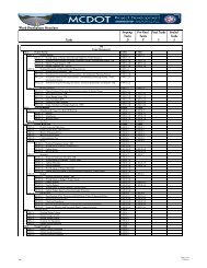
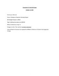
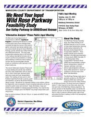
PROJECTSouth Phoenix Two Basins Project43rd Avenue & Baseline RoadPhoenix, ArizonaJOB NO.DepthinFeetDrillRateMin/ft.17-2011-4055GraphicalLogSampleSample TypeDATEBlow Count6/18/12Dry Densitylbs. perCubic ft.MoistureContentPercent <strong>of</strong>Dry WeightUnified SoilClassificationLOCATIONRIG TYPEBORING TYPESURFACE ELEV.DATUMREMARKSSee Site MapCME-756 5/8" Hollow Stem Auger1027'±Stanley Base MapVISUAL CLASSIFICATION0SA9-9-9CLslightly moistfirmSANDY CLAY, predominantly fine to mediumgrained, subangular to subrounded sand,uncemented with occasional strongly cementedpieces, low to medium plasticity, light brownU17976note: increase in fines & occasional fine grained,subangular to subrounded gravel below 2'5SA5-6-10slightly moistnote: occasional fine grained, subangular tosubrounded gravel, considerable fine to mediumgrained, subangular to subrounded sand, lightbrown to biege below 4'firm to hard10U50/5"10912note: strongly cemented lenses at 10' & below15S28-13-14slightly moistto moistnote: slightly moist to moist below 15' & decreasein fines20U40SCslightly moistto moistvery firmCLAYEY SAND, occasional to somepredominantly fine grained, subangular gravel,predominantly fine to medium grained,subangular to subrounded, low to mediumplasticity, brown to light brown25DEPTH(ft)HOURnoneSGROUNDWATER11-14-17DATESAMPLE TYPESPA - Drill cuttingsS - 2" O.D. 1.38" I.D. tube sampleU - 3" O.D. 2.42" I.D. tube sampleP - Pressuremeter TestNR - No Recoveryslightly moistto moistdenseSAND, occasional fine grained, subangular tosubrounded gravel, predominantly mediumgrained, subangular to subrouned, nonplastic,grayish-brownLOG OF TEST BORING NO.PageB-41<strong>of</strong>2
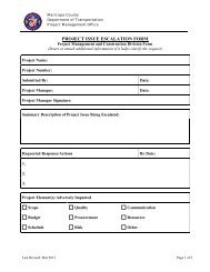
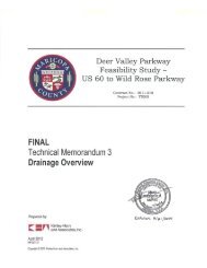
PROJECTSouth Phoenix Two Basins Project43rd Avenue & Baseline RoadPhoenix, ArizonaJOB NO.DepthinFeetDrillRateMin/ft.17-2011-4055GraphicalLogSampleSample TypeDATEBlow Count6/18/12Dry Densitylbs. perCubic ft.MoistureContentPercent <strong>of</strong>Dry WeightUnified SoilClassificationLOCATIONRIG TYPEBORING TYPESURFACE ELEV.DATUMREMARKSSee Site MapCME-756 5/8" Hollow Stem Auger1027'±Stanley Base MapVISUAL CLASSIFICATION25SPSAND, continuedStopped Auger at 24'6"Stopped Sampler at 26'Backfilled with drill cuttings3035404550GROUNDWATERDEPTH(ft) HOUR DATEnoneSAMPLE TYPEA - Drill cuttingsS - 2" O.D. 1.38" I.D. tube sampleU - 3" O.D. 2.42" I.D. tube sampleP - Pressuremeter TestNR - No RecoveryLOG OF TEST BORING NO.PageB-42<strong>of</strong>2
APPENDIX BLaboratory Test Results
<strong>Geotechnical</strong> Investigation <strong>Report</strong>43rd Avenue and Baseline Road BasinTABLE B-1SUMMARY OF LABORATORY TEST RESULTSProject LocationBoring NumberBeginDepth(ft)EndUSCS/Group SymbolPercent Fines(minus 200)Optimum MoistureContent (%)(by ASTM D698A)Maximum Dry Density(pcf) (by ASTM D698Aor D698C)43rd Avenue and Basline Road B-4 0.0 5.0 CL 52 31 13 12.5 119.543rd Avenue and Basline Road B-4 2.0 3.0 5.7 96.843rd Avenue and Basline Road B-4 5.0 10.0 CL 63 31 11 18.3 107.943rd Avenue and Basline Road B-4 9.5 9.9 12.0 109.143rd Avenue and Basline Road B-4 14.5 16.0 156 8043rd Avenue and Basline Road B-4 19.5 20.5 52 27Liquid LimitPlasticity IndexMoisture Content(%)In Place Dry Density(pcf) 1Chlorides(ppm) 2Soluble Sulfates(ppm) 2MEANSTDEVMAXIMUMMINIMUMCOUNT57.5 31.0 12.0 8.9 103.0 15.4 113.7 104.0 53.57.8 0.0 1.4 4.5 8.7 4.1 8.2 73.5 37.563 31 13 12.0 109.1 18 120 156 8052 31 11 5.7 96.8 13 108 52 272 2 2 2 2 2 2 2 2South Mountain Two Basins ProjectWork Assignment #2<strong>Maricopa</strong> <strong>County</strong> July 17, 2012Notes: 1(pcf) = pounds per cubic foot2(ppm) = parts per million
APPENDIX CPrevious <strong>Geotechnical</strong> Investigation