Lennox HP29
Lennox HP29
Lennox HP29

You also want an ePaper? Increase the reach of your titles
YUMPU automatically turns print PDFs into web optimized ePapers that Google loves.
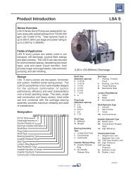
1 − Compressor Cover (Figure 9)A compressor cover COVERconstructed of vinyl-facedfiberglass is used on all<strong>HP29</strong> units. The coverprovides an acoustic barrier.The cover slides over thecompressor and is heldsecure with snap buttons.Slits are provided forinstallation around thedischarge and suction lines.FIGURE 9SLIT FORSUCTIONLINESNAPBUTTONSCOMPRESSORSLIT FOR DISCHARGE LINE2 − Crankcase HeaterA crankcase heater is used on all <strong>HP29</strong> units equipped witha reciprocating compressor. The well−mountedinsertion−type heater is self−regulating. See table 8 forcrankcase heater specifications.TABLE 8<strong>HP29</strong> CRANKCASE HEATER RATINGSUnitRating (Watts)<strong>HP29</strong>−211/-261/-311/-41040 watts<strong>HP29</strong>-460,-510and-65027 watts<strong>HP29</strong>−018/−024/−03040 watts<strong>HP29</strong>−04227 wattsC − Condenser Fan MotorAll units use single−phase PSC fan motors which require a runcapacitor. In all <strong>HP29</strong> units, (except "G" and "J" voltage) theoutdoor fan is controlled by the CMCI defrost board.ELECTRICAL DATA tables in this manual showspecifications for outdoor fans used in <strong>HP29</strong>s.Access to the outdoor fan motor on all units is gained byremoving the seven screws securing the fan assembly.See figure 10. The outdoor fan motor is removed fromthe fan guard by removing the four nuts found on the toppanel. If condenser fan motor must be replaced, alignfan hub flush with motor shaft.Remove (7) screwsRemove (4) nutsCONDENSER FAN MOTORAND COMPRESSOR ACCESSFANALIGN FAN HUBFLUSH WITHMOTOR SHAFTFAN GUARDWIRING DRIPLOOPREMOVE (7) SCREWSSECURING FAN GUARD.REMOVE FAN GUARD/FAN ASSEMBLY.FIGURE 10D − Reversing Valve L1 and SolenoidA refrigerant reversing valve with electromechanicalsolenoid is used to reverse refrigerant flow during unitoperation. The reversing valve requires no maintenance.It is not repairable. If the reversing valve has failed, it mustbe replaced.If replacement is necessary, access reversing valve byremoving the outdoor fan motor. Refer to figure 10.III − REFRIGERANT SYSTEMRefer to figure 11 for refrigerant flow in the cooling modes.The reversing valve is energized during cooling demandand during defrost.A − Liquid and Vapor Line Service ValvesThe liquid and vapor line service valves (figures 12 and 13)and gauge ports are accessible from outside the unit.Each valve is equipped with a service port. The service portsare used for leak testing, evacuating, charging and checkingcharge. A schrader valve is factory installed. A service port capis supplied to protect the schrader valve from contaminationand serve as the primary leak seal.NOTE-Always keep valve stem caps clean.DEFROST THERMOSTATOUTDOOR UNITDISTRIBUTORHEATING MODEEXPANSION/CHECKVALVEBI-FLOWFILTER / DRIEROUTDOORCOILREVERSING VALVELOWPRESSUREHIGHPRESSUREINDOOR UNITMUFFLERTOHCFC22DRUMCOMPRESSORSUCTIONSERVICEPORTVAPORLINEVALVELIQUID LINESERVICE PORTTHERMOMETERWELLEXPANSION/CHECKVALVENOTE − ARROWS INDICATE DIRECTION OF REFRIGERANT FLOWFIGURE 11INDOORCOILPage 10