Lennox HP29
Lennox HP29
Lennox HP29

Create successful ePaper yourself
Turn your PDF publications into a flip-book with our unique Google optimized e-Paper software.
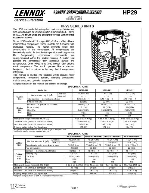
Service LiteratureCorp. 9709−L5Revised 8−2004<strong>HP29</strong> SERIES UNITSThe <strong>HP29</strong> is a residential split-system heat pump. Outdoor coilsize, circuiting and air volume result in a minimum SEER ratingof 10.0. All <strong>HP29</strong> units are designed for use with thermalexpansion valves.<strong>HP29</strong>Some <strong>HP29</strong> units (−211 through −650, −018 and −024) utilize areciprocating compressor. These models are furnished withcrankcase heaters. The heater prevents liquid fromaccumulating in the compressor. All compressors arehermetically sealed for trouble-free operation and long servicelife. Reciprocating compressor components arespring-mounted within the sealed housing. A built-in limitprotects the compressor from excessive current andtemperatures. Other <strong>HP29</strong> units (−030 through −060) utilize ascroll compressor. The scroll operates like a standardheatpump, but is unique in the way that it compressesrefrigerant.This manual is divided into sections which discuss majorcomponents, refrigerant system, charging procedures,maintenance, and operation sequence .All specifications in this manual are subject to change.SPECIFICATIONSModel No. <strong>HP29</strong>-211 <strong>HP29</strong>-261 <strong>HP29</strong>-311Outer coil 11.41 (1.06) 11.41 (1.06) 13.31 (1.24)Ntf Net face area - sq. ft. ft( (m 2 ) OutdoorInner coil - - - - - - - - - - - -Coil Tube diameter in. (mm) & no. of rows 5/16 (7.9) 1 5/16 (7.9) 1 5/16 (7.9) 1Fins per inch (m) 22 (866) 22 (866) 22 (866)Diameter in. (mm) & no. of blades 18 (457) 3 18 (457) 3 18 (457) 4Outdoor Motor hp (W) 1/6 (124) 1/6 (124) 1/6 (124)Coil Cfm (L/s) 2400 (1135) 2400 (1135) 2500 (1180)Fan Rpm 1105 1105 1100Watts 180 180 200*Refrigerant charge furnished (HCFC-22) 4 lbs. 5 oz. (1.96 kg) 4 lbs. 4 oz. (1.92 kg) 4 lbs. 15 oz. (2.24 kg)Liquid line in. (mm) o.d. connection (sweat) **3/8 to 5/16 (8) **3/8 to 5/16 (8) **3/8 to 5/16 (8)Vapor line in. (mm) o.d. connection (sweat) 5/8 (15.9) 5/8 (15.9) 3/4 (19.1)Shipping weight lbs. (kg) 1 package 152 (69) 152 (69) 164 (74)*Refrigerant charge sufficient for 20 ft. (6.1 m) length of refrigerant lines.**5/16 to 3/8 reducer coupling supplied with unit.SPECIFICATIONSModel No. <strong>HP29</strong>-411/<strong>HP29</strong>-41 <strong>HP29</strong>-461/<strong>HP29</strong>-463 <strong>HP29</strong>-511/<strong>HP29</strong>-513 <strong>HP29</strong>-651/<strong>HP29</strong>-653Outer coil 15.21 (1.41) 15.21 (1.41) 15.21 (1.41) 15.21 (1.41)Net face area - sq. ft. (m 2 )OutdoorInner coil - - - - 5.44 (0.51) 5.44 (0.51) 14.50 (13.5)Coil Tube diameter in. (mm) & no. of rows 5/16 (7.9) 1 5/16 (7.9) 1.37 5/16 (7.9) 1.37 5/16 (7.9) 2Fins per inch (m) 22 (866) 22 (866) 22 (866) 22 (866)Diameter in. (mm) & no. of blades 18 (457) 4 18 (457) 4 18 (457) 4 18 (457) 4Outdoor Motor hp (W) 1/6 (124) 1/6 (124) 1/3 (249) 1/3 (249)Coil Cfm (L/s) 2520 (1190) 2500 (1180) 2950 (1390) 2930 (1385)Fan Rpm 1100 1100 1100 1100Watts 200 200 310 310*Refrigerant charge furnished (HCFC-22) 6 lbs. 3 oz. (2.81 kg) 7 lbs. 13 oz. (3.54 kg) 7 lbs. 1 oz. (3.20 kg) 9 lbs. 0 oz. (4.08 kg)Liquid line in. (mm) o.d. connection (sweat) 3/8 (9.5) 3/8 (9.5) 3/8 (9.5) 3/8 (9.5)Vapor line in. (mm) o.d. connection (sweat) 3/4 (19.1) 7/8 (22.2) 7/8 (22.2) 1-1/8 (28.6)Shipping weight lbs. (kg) 1 package 174 (79) 199 (90) 206 (93) 221 (100)*Refrigerant charge sufficient for 20 ft. (6.1 m) length of refrigerant lines.Page 1© 1997 <strong>Lennox</strong> Industries Inc.Litho U.S.A.
1 − Transformer T5Transformer T5 is used on all J" voltage units. T5 is used as astep-down transformer for the outdoor fan motor. Thetransformer is located inside the unit control box (see figure 3).The transformer is rated at 3.4 VA with a 575 volt primary anda 460 volt secondary.<strong>HP29</strong> THREE-PHASE UNIT CONTROL BOXRUN CAPACITOR(C1)COMPRESSORCONTACTOR(K1)TRANSFORMER(T5)J" VOLTAGEUNITS ONLYOUTDOOR FANRELAY (K10) G"& J" VOLTAGEUNITS ONLY2 − Dual Capacitor C12The compressor (scroll or reciprocating) and fan insingle-phase units use permanent split capacitor motors. Thecapacitor is located inside the unit control box (see figure 4 and5). A single dual" capacitor (C12) is used for both the fanmotor and the compressor (see unit wiring diagram). The fanside and the compressor side of the capacitor have differentMFD ratings. See table 1 for dual capacitor ratings.<strong>HP29</strong> SINGLE−PHASE UNIT CONTROL BOXWITH SCROLL COMPRESSORCOMPRESSORCONTACTOR(K1)DUAL CAPACITOR(C12)GROUNDINGLUGDEFROSTCONTROL(CMC1)GROUNDINGLUGDEFROSTCONTROL(CMC1)STARTCAPACITOR(C7)COMPRESSORCONTACTOR(K1)FIGURE 3<strong>HP29</strong> SINGLE-PHASE UNIT CONTROL BOX WITHRECIPROCATING COMPRESSORGROUNDINGLUGFIGURE 4DUAL CAPACITOR(C12)POTENTIALRELAY (K31)DEFROSTCONTROL(CMC1)<strong>HP29</strong>−461/511<strong>HP29</strong>−651<strong>HP29</strong>−018<strong>HP29</strong>−024<strong>HP29</strong>−030<strong>HP29</strong>−036<strong>HP29</strong>−042<strong>HP29</strong>−048<strong>HP29</strong>−060FANHERMFANHERMFANHERMFANHERMFANHERMFANHERMFANHERMFIGURE 5<strong>HP29</strong> (C12) DUAL CAPACITOR RATINGUnit Terminal MFD VACFAN5<strong>HP29</strong>−211HERM25<strong>HP29</strong>−261FAN5HERM30FAN5<strong>HP29</strong>−311370HERM35<strong>HP29</strong>−411FANTABLE 15407.5507.5705255305355407.5407.5607.580HERMFANHERMFANHERM 440370440370Page 4
3 − Potential Relay K31 (Start)All single-phase units with a reciprocating compressor,use a potential relay which controls the operation of thestarting circuit. The potential relay is located inside theunit control box (see figure 4). The relay is normally closedwhen contactor K1 is de-energized. When K1 energizes,the compressor immediately begins start-up. K31remains closed during compressor start-up and startcapacitor C7 remains in the circuit. When the compressorreaches approximately 75% of its speed, K31 isenergized. When K1 energizes, the contacts open andstart capacitor C7 is taken out of the circuit. Potentialrelays are critically matched to the specific compressorapplied.4 − Start Capacitor C7All single-phase units with a reciprocating compressor,use a start capacitor (C7). C7 is located inside the unitcontrol box (see figure 4). C7 is wired in parallel with thecompressor side of the dual capacitor.See table 2 forstartcapacitor ratings.TABLE 2<strong>HP29</strong> START CAPACITOR RATING (C7)Unit MFD VAC<strong>HP29</strong>−211/261/311 145−175 330<strong>HP29</strong>−411 189−227 330<strong>HP29</strong>−461/511/651 176−216216<strong>HP29</strong>−018/024 145−175 3305 − Run Capacitor C1The fan in all three−phase units uses a single-phasepermanent split capacitor motor. A single capacitor C1 is usedfor the fan motor. C1 is located inside the unit control box (seefigure 3). Table 3 shows the ratings of C1.TABLE 3<strong>HP29</strong> RUN CAPACITOR RATING (C1)Unit MFD VAC<strong>HP29</strong>−413/463/5135 370<strong>HP29</strong>-6537.5 370<strong>HP29</strong>−036 5 370<strong>HP29</strong>−042/048/060 7.5 3706 − Outdoor Fan Relay K10Outdoor fan relay K10 is used on all G" and J" voltageunits to energize the outdoor fan B4. The relay is locatedin the control box and is a single-pole double-throwrelay. See figure 3. K10 is energized by the indoorthermostat terminal Y1 (24V). When K10 is energized, aset of N.O. contacts closes to energize the outdoor fan.7 − Compressor Contactor K1The compressor is energized by a contactor located in thecontrol box. See figures 3, 4, and 5. Single−pole andtwo-pole contactors are used in single-phase units andthree-pole contactors are used in three-phase units. Seewiring diagrams for specific unit. K1 is energized by the indoorthermostat terminal Y1 (24V). Single−phase <strong>HP29</strong> units are notequipped with a 24V transformer. All 24 VAC controls arepowered by the indoor unit. Refer to unit wiring diagram. "J"voltage units only are equipped with a 24V transformer. Seefigure 3.Page 5DANGERElectric Shock Hazard.May cause injury or death.Disconnect all remote electrical powersupplies berore opening unit panel. Unitmay have multiple power supplies.Some units are equipped with single−pole contactors. When unit is equippedwith a single−pole contactor, line voltageis present at all components (even whenunit is not in operation).8 − Defrost System <strong>HP29</strong>Unit built prior to April 2002The <strong>HP29</strong> defrost system includes two components: adefrost thermostat and a defrost control.ELECTROSTATIC DISCHARGE (ESD)Precautions and ProceduresCAUTIONElectrostatic discharge can affect electroniccomponents. Take precautions during unit installationand service to protect the unit’s electroniccontrols. Precautions will help to avoid controlexposure to electrostatic discharge by puttingthe unit, the control and the technician at thesame electrostatic potential. Neutralize electrostaticcharge by touching hand and all tools on anunpainted unit surface before performing anyservice procedure.Defrost Thermostat S6The defrost thermostat is mounted on the liquid linebetween the check/expansion valve and the distributor.<strong>HP29</strong>−211 through −653 have a defrost setting of 35F(2C) and <strong>HP29</strong>−018 through −060 have a defrost settingof 42F (5.5C). When defrost thermostat senses thesetpoint or cooler, its contacts close and send a signal tothe defrost control board to start the defrost timing. Italso terminates defrost when the liquid line warms up to70F (21C).Defrost Control CMC1The defrost control board in the <strong>HP29</strong> series units has thecombined functions of a time/temperature defrost control,defrost relay, diagnostic LEDs and field connection terminalstrip.The control provides automatic switching from normalheating operation to defrost mode and back. Duringcompressor cycle (room thermostat demand cyle), if theO" input is not on and the defrost thermostat is closed, thecontrol accumulates compressor run times at 30-, 60- or90-minute field adjustable intervals. If the defrostthermostat remains closed when the accumulatedcompressor run time ends, the defrost relay is energizedand defrost begins.
PRESSURE SWITCHSAFETY CIRCUITCONNECTIONSNOTE − COMPONENT LOCATIONS WILL VARY WITH BOARD MANUFACTURERPRESSURE SWITCHSAFETY CIRCUITCONNECTIONSDIAGNOSTIC LEDsCONNECTION FORONE OPTIONALSWITCHHighPressureSwitchS4FACTORY−INSTALLEDJUMPER(Remove to addpressure switches)DIAGNOSTIC LEDsFACTORY−INSTALLEDJUMPER(Remove to addpressure switches)DEFROSTINTERVALTIMING PINSCONNECTIONS FORTWO OPTIONALSWITCHESAMBIENTTHERMISTORCONNECTIONOptionalswitchSERVICE LIGHTCONNECTIONS4HighPressureSwitchDEFROST INTERVALTIMING PINS24V TERMINAL STRIPCONNECTIONS24V TERMINAL STRIPCONNECTIONSFIGURE 6Defrost Control Timing PinsEach timing pin selection provides a differentaccumulated compressor run period during onethermostat run cycle. A defrost cycle is initiated at theend of this run period. The defrost interval can beadjusted to 30, 60 or 90 minutes. See figure 6. Thedefrost period is a maximum of 14 minutes and cannotbe adjusted. If no timing is selected, the control defaultsto 90 minutes.A TEST option is provided for troubleshooting. When thejumper is placed across the TEST pins, the timing of allfunctions is reduced by a factor of 128. For example, a 30minute interval during TEST is 14 seconds and the 14minute defrost is reduced to 6.5 seconds.The TEST mode may be started at any time. If the jumperis in the TEST position at power−up or for longer than fiveminutes, the control will ignore the TEST selection and willdefault to a 90 minute interval. In order to test defrostcycle, defrost thermostat must be closed or jumpered.Once defrost is initiated, remove jumper immediately.Failure to remove jumper will reduce defrost cycle toapproximately 3 seconds.Pressure Switch Safety CircuitThe defrost control incorporates a pressure switch safetycircuit that allows the application of up to two safety devices:high pressure and/or loss of charge. See figure 6. When thepressure switch opens, unit operation is suspended untilpressure switch closes. If the pressure switch opens for a thirdtime during one thermostat demand, the board will lockout untillow voltage is reset. This can be done by breaking 24 voltpower to terminal R" on the defrost control board.When only one pressure switch is used, wire the switch to thetwo outside terminals of the pressure switch connections.NOTE: If not using a pressure switch, the factory−installedjumper wire must be connected.Diagnostic LEDsThe defrost board uses two LEDs for diagnostics. The LEDsflash a specific sequence according to the condition.TABLE 4DEFROST CONTROL BOARD DIAGNOSTIC LEDMODE LED 1 LED 2Normal Operation/Power to boardFlash together withLED 2Pressure Switch Open Off OnBoard Malfunction On OnFlash together withLED 1Page 6
9 − Defrost SystemUnits built April 2002 and laterThe <strong>HP29</strong> defrost system includes two components: adefrost thermostat and a defrost control.Defrost ThermostatThe defrost thermostat is located on the liquid line betweenthe check/expansion valve and the distributor. Whendefrost thermostat senses 42°F (5.5°C) or cooler, thethermostat contacts close and send a signal to the defrostcontrol board to start the defrost timing. It also terminatesdefrost when the liquid line warms up to 70°F (21°C).Defrost ControlThe defrost control board includes the combinedfunctions of a time/temperature defrost control, defrostrelay, diagnostic LEDs and terminal strip for field wiringconnections. See figure 7.The control provides automatic switching from normalheating operation to defrost mode and back. Duringcompressor cycle (call for defrost), the controlaccumulates compressor run times at 30, 60, or 90 minutefield−adjustable intervals. If the defrost thermostat is closedwhen the selected compressor run time interval ends, thedefrost relay is energized and defrost begins.Defrost Control Timing PinsEach timing pin selection provides a differentaccumulated compressor run time period during onethermostat run cycle. This time period must occur beforea defrost cycle is initiated. The defrost interval can beadjusted to 30 (T1), 60 (T2), or 90 (T3) minutes. Seefigure 7. The defrost timing jumper is factory−installed toprovide a 60−minute defrost interval. If the timing selectorjumper is not in place, the control defaults to a 90−minutedefrost interval.The maximum defrost period is 14minutes and cannot be adjusted.A TEST option is provided for troubleshooting. The TESTmode may be started any time the unit is in the heatingmode and the defrost thermostat is closed orjumpered. If the jumper is in the TEST position atpower-up, the control will ignore the test pins. When thejumper is placed across the TEST pins for two seconds, thecontrol will enter the defrost mode. If the jumper is removedbefore an additional 5−second period has elapsed (7seconds total), the unit will remain in defrost mode until thedefrost thermostat opens or 14 minutes have passed. If thejumper is not removed until after the additional 5−secondperiod has elapsed, the defrost will terminate and the testoption will not function again until the jumper is removedand re−applied.<strong>HP29</strong> DEFROST CONTROL BOARDSTANDARD UNITSOPTIONAL UNITSHIGH PRESSURE SWITCHSAFETY CIRCUITCONNECTIONSNOTE − Remove factory−installed jumper to addpressure switch.CONNECTION FOROPTIONALHIGH PRESSURESWITCHCCYDEFROSTINTERVALTIMING PINSDIAGNOSTICLEDsPRESSURE SWITCHTERMINALS(Remove factory−installed jumperto installpressure switch.)DEFROSTINTERVALTIMINGPINSCCYDIAGNOSTICLEDsSERVICELIGHTTERMINALSAMBIENTTHERMISTERTERMINALS24VTERMINALSTRIPHighPressureSwitch24VTERMINALSTRIPS4FIGURE 7Page 7
Pressure Switch CircuitThe defrost control incorporates a pressure switch circuitthat allows the application of an optional high pressureswitch. See figure 7. During a demand cycle, the defrostcontrol will lock out the unit if the optional high pressureswitch opens. The diagnostic LEDs will display a pattern foran open high pressure switch. See table 5. The unit willremain locked out until the switch resets or is reset.Remove the factory-installed jumper before connecting theoptional high pressure switch to the control board.NOTE − If not using a pressure switch, the factory-installedjumper wire must be connected.Diagnostic LEDsThe defrost board uses two LEDs for diagnostics. The LEDsflash a specific sequence according to the condition.TABLE 5DEFROST CONTROL BOARD DIAGNOSTIC LEDMODE LED 1 LED 2Normal operation /power to boardSynchronizedFlash with LED 2Board failure or no power Off OffBoard failure On OnHigh pressure switch open Flash OnLow pressure switch open* On FlashPressure switch lockout* On OffAnti−short−cycle /5−minute delay**Optional units only.Optional UnitsAlternating Flashwith LED 2SynchronizedFlash with LED 1Alternating Flashwith LED 1Optional units include a defrost control which includes atimed−off delay and a second pressure switch circuit.Time−Delay RelayThe time delay is five minutes long. The delay featureprotects the compressor in cased of an interruption inpower to the unit. The time delay may be bypassed byplacing the temperature select jumper across the TESTpins for 0.5 seconds.Pressure Switch CircuitThe defrost control board used in optional units includes athree−strike lock−out feature and LO PS terminals toaccommodate the addition of a field−provided low pressureor loss of charge pressure switch. See figure 7.During a single demand cycle, the defrost control will lockout the unit after the third time that the circuit is interruptedby any pressure switch that is wired to the control board. Inaddition, the diagnostic LEDs will indicate a locked outpressure switch after the third occurrence of an openpressure switch. See table 5. The unit will remain lockedout until power is broken then remade to the control or untilthe jumper is applied to the TEST pins for 0.5 seconds.NOTE − The defrost control board ignores input from thelow pressure switch terminals during the TEST mode,during the defrost cycle, during a 90−second start−upperiod, and for the first 90 seconds each time the reversingvalve switches heat/cool modes. If the TEST pins arejumpered and the 5−minute delay is being bypassed,the LO PS terminal signal is not ignored during the90−second start−up period.Ambient Thermister & Service Light ConnectionOptional units include a defrost control board whichprovides terminal connections for an ambient thermistorand a service light. The thermistor compensates forchanges in ambient temperature which might causethermostat droop. The service light thermostat provides asignal which activates the room thermostat service lightduring periods of inefficient operation.Page 8
B − Compressor (Reciprocating & Scroll)DANGERMake sure all power is disconnected beforebeginning electrical service procedures.Some <strong>HP29</strong> units utilize a conventional reciprocatingcompressor. Table 6 shows the specifications of reciprocatingcompressors used in <strong>HP29</strong> series units.TABLE 6<strong>HP29</strong> COMPRESSOR SPECIFICATIONSUnit MAN/MODEL Voltage Phase LRA RLA Oil fl.oz.<strong>HP29</strong>−211 COP/CR16K6−PFV 208/230 1 49 8.6 45<strong>HP29</strong>−211 TEC/AWD5516EXD 208/230 1 48.3 7.9 32<strong>HP29</strong>−261<strong>HP29</strong>−261COP/CR22K6−PFV 208/230TEC/AWD5522EXD 208/2301156609.810.064532<strong>HP29</strong>−311 COP/CR28K6−PFV 208/230 1 75 13.7 45<strong>HP29</strong>−411<strong>HP29</strong>−413COP/CR34K6−PFV 208/230COP/CR35K6−TF5 208/23013967516.210.34545<strong>HP29</strong>−413 COP/CR35K6−TFD 460 3 40 4.3 45<strong>HP29</strong>−461 TEC/AV554OF 208/230 1 92 17.5 54<strong>HP29</strong>−463 TEC/AV5540F 208/230 3 87 12.8 54<strong>HP29</strong>−463 TEC/AV5540F 460 3 44 6.4 54<strong>HP29</strong>−511 TEC/AV5545F 208/230 1 110 23.4 54<strong>HP29</strong>−513 TEC/AV5545F 208/230 3 91 14.0 54<strong>HP29</strong>−513 TEC/AV5545F 460 3 46 7.1 54<strong>HP29</strong>−513 TEC/AV5545F 575 3 37 5.8 54<strong>HP29</strong>−651 TEC/AV5558F 208/230 1 123 26.9 54<strong>HP29</strong>−653<strong>HP29</strong>−653TEC/AV5558FTEC/AV5558F208/230460331286417.39.05454<strong>HP29</strong>−653 TEC/AV5558F 575 3 51 7.1 54<strong>HP29</strong>−018 COP/CR16K6−PFV 208/230 1 49 7.9 45<strong>HP29</strong>−024 COP/CR22K6−PFV 208/230 1 60 10.1 45<strong>HP29</strong>−036 TEC/AVD5535EXT 208/230 3 75 10.3 54<strong>HP29</strong>−036 TEC/AVD5535EXG 460 3 37.5 5.6 54<strong>HP29</strong>−042 TEC/AV5540F 208/230 3 87 12.8 54<strong>HP29</strong>−042 TEC/AV5540F 460 3 44 6.4 54Some <strong>HP29</strong> units utilize a scroll compressor. The scrollcompressor design is simple, efficient and requires fewmoving parts. A cutaway diagram of the scroll compressor isshown in figure 8. The scrolls are located in the top of thecompressor can and the motor is located just below. The oillevel is immediately below the motor.SCROLL COMPRESSORDISCHARGEThe scroll is a simple compression concept centered aroundthe unique spiral shape of the scroll and its inherent properties.Two identical scrolls are mated together forming concentricspiral shapes. One scroll remains stationary, while the other isallowed to "orbit." The orbiting scroll does not rotate or turn butmerely orbits the stationary scroll. Due to its efficiency, thescroll compressor is capable of drawing a much deepervacuum than reciprocating compressors. Deep vacuumoperation can cause internal fusite arcing resulting indamaged internal parts and will result in compressorfailure. Never use a scroll compressor for evacuating orfor deep vacuum operation (operating compressor at 0psig or lower) on the system. Table 7 shows thespecifications of scroll compressors used in the <strong>HP29</strong>series units.TABLE 7<strong>HP29</strong> COMPRESSOR SPECIFICATIONSUnit MAN/MODEL Voltage Phase LRA RLA Oil fl.oz.<strong>HP29</strong>−030 COP/ZR30KC−PFV 208/230 1 84 14.7 42<strong>HP29</strong>−036<strong>HP29</strong>−042COP/ZR36KC−PFVCOP/ZR42KC−PFV208/230208/230111001271620.34242<strong>HP29</strong>−048 COP/ZR46K3−PFV 208/230 1 129 23.7 66<strong>HP29</strong>−048<strong>HP29</strong>−048<strong>HP29</strong>−048COP/ZR46K3−TF5COP/ZR46K3−TFDCOP/ZR46K3−TFE208/23046057533312049.54013.57.45.8727272<strong>HP29</strong>−060<strong>HP29</strong>−060COP/ZR61K3−PFVCOP/ZR61K3−TF5208/230208/23013169 28.8137 17.35672<strong>HP29</strong>−060 COP/ZR61K3−TFD 460 3 62 9 72<strong>HP29</strong>−060 COP/ZR61K3−TFE 575 3 50 7.1 72Three-Phase Compressor RotationThree-phase scroll compressors must be phasedsequentially to ensure correct compressor rotation andoperation. At compressor start-up, a rise in discharge anddrop in suction pressures indicates proper compressorphasing and operation. If discharge and suction pressuresdo not perform normally, follow the steps below to correctlyphase the unit.1 − Disconnect power to the unit.2 − Reverse any two field power leads to the unit.3 − Reapply power to the unit.Discharge and suction pressures should operate withintheir normal start-up ranges.NOTE − Compressor noise level may be significantly higherwhen phasing is incorrect and the unit will not providecooling when compressor is operating backwards.Continued backward operation will cause the compressorto cycle on internal protector.SUCTIONFIGURE 8Page 9
1 − Compressor Cover (Figure 9)A compressor cover COVERconstructed of vinyl-facedfiberglass is used on all<strong>HP29</strong> units. The coverprovides an acoustic barrier.The cover slides over thecompressor and is heldsecure with snap buttons.Slits are provided forinstallation around thedischarge and suction lines.FIGURE 9SLIT FORSUCTIONLINESNAPBUTTONSCOMPRESSORSLIT FOR DISCHARGE LINE2 − Crankcase HeaterA crankcase heater is used on all <strong>HP29</strong> units equipped witha reciprocating compressor. The well−mountedinsertion−type heater is self−regulating. See table 8 forcrankcase heater specifications.TABLE 8<strong>HP29</strong> CRANKCASE HEATER RATINGSUnitRating (Watts)<strong>HP29</strong>−211/-261/-311/-41040 watts<strong>HP29</strong>-460,-510and-65027 watts<strong>HP29</strong>−018/−024/−03040 watts<strong>HP29</strong>−04227 wattsC − Condenser Fan MotorAll units use single−phase PSC fan motors which require a runcapacitor. In all <strong>HP29</strong> units, (except "G" and "J" voltage) theoutdoor fan is controlled by the CMCI defrost board.ELECTRICAL DATA tables in this manual showspecifications for outdoor fans used in <strong>HP29</strong>s.Access to the outdoor fan motor on all units is gained byremoving the seven screws securing the fan assembly.See figure 10. The outdoor fan motor is removed fromthe fan guard by removing the four nuts found on the toppanel. If condenser fan motor must be replaced, alignfan hub flush with motor shaft.Remove (7) screwsRemove (4) nutsCONDENSER FAN MOTORAND COMPRESSOR ACCESSFANALIGN FAN HUBFLUSH WITHMOTOR SHAFTFAN GUARDWIRING DRIPLOOPREMOVE (7) SCREWSSECURING FAN GUARD.REMOVE FAN GUARD/FAN ASSEMBLY.FIGURE 10D − Reversing Valve L1 and SolenoidA refrigerant reversing valve with electromechanicalsolenoid is used to reverse refrigerant flow during unitoperation. The reversing valve requires no maintenance.It is not repairable. If the reversing valve has failed, it mustbe replaced.If replacement is necessary, access reversing valve byremoving the outdoor fan motor. Refer to figure 10.III − REFRIGERANT SYSTEMRefer to figure 11 for refrigerant flow in the cooling modes.The reversing valve is energized during cooling demandand during defrost.A − Liquid and Vapor Line Service ValvesThe liquid and vapor line service valves (figures 12 and 13)and gauge ports are accessible from outside the unit.Each valve is equipped with a service port. The service portsare used for leak testing, evacuating, charging and checkingcharge. A schrader valve is factory installed. A service port capis supplied to protect the schrader valve from contaminationand serve as the primary leak seal.NOTE-Always keep valve stem caps clean.DEFROST THERMOSTATOUTDOOR UNITDISTRIBUTORHEATING MODEEXPANSION/CHECKVALVEBI-FLOWFILTER / DRIEROUTDOORCOILREVERSING VALVELOWPRESSUREHIGHPRESSUREINDOOR UNITMUFFLERTOHCFC22DRUMCOMPRESSORSUCTIONSERVICEPORTVAPORLINEVALVELIQUID LINESERVICE PORTTHERMOMETERWELLEXPANSION/CHECKVALVENOTE − ARROWS INDICATE DIRECTION OF REFRIGERANT FLOWFIGURE 11INDOORCOILPage 10
IMPORTANTService valves are closed to the heat pump unitand open to line set connections. Do not open untilrefrigerant lines have been leak tested andevacuated. All precautions should be exercised tokeep the system free from dirt, moisture and air.To Access Schrader Port:1 − Remove service port cap with an adjustable wrench.2 − Connect gauge to the service port.3 − When testing is completed, replace service port cap.Tighten finger tight, then an additional 1/6 turn.To Open Liquid or Vapor Line Service Valve:1 − Remove stem cap with an adjustable wrench.2 − Using service wrench and hex head extension (5/16 forvapor line and 3/16 for liquid line), back the stem outcounterclockwise until the valve stem just touches theretaining ring.3 − Replace stem cap tighten firmly. Tighten finger tight, thentighten an additional 1/6 turn.LIQUID LINE SERVICE VALVE (VALVE OPEN)INSERT HEXWRENCH HERESTEM CAPOUTLET (TOCOMPRESSOR)SERVICEPORTDANGERDo not attempt to backseat this valve. Attempts tobackseat this valve will cause snap ring to explodefrom valve body under pressure of refrigerant.Personal injury and unit damage will result.To Close Liquid or Vapor Line Service Valve:1 − Remove stem cap with an adjustable wrench.2 − Using service wrench and hex head extension (5/16 forvapor line and 3/16 for liquid line), turn stem clockwise toseat the valve. Tighten firmly.3 − Replace stem cap. Tighten finger tight, then tighten anadditional 1/6 turn.VAPOR LINE SERVICE VALVE (VALVE OPEN)INSERT HEXSTEM CAPWRENCH HEREINLET (TOINDOOR COIL)SCHRADERVALVESERVICE PORTCAPOUTLET (TOCOMPRESSOR)SERVICE PORTVAPOR LINE SERVICE VALVE (VALVE CLOSED)INLET (TORETAINING RINGSTEM CAPINDOOR COIL)SERVICEPORTCAPSCHRADERVALVESERVICEPORTSERVICEPORT CAPSCHRADER VALVE OPENTO LINE SET WHEN VALVE ISCLOSED (FRONT SEATED)FIGURE 12INLET (TOINDOOR COIL)LIQUID LINE SERVICE VALVE (VALVE CLOSED)RETAINING RING STEM CAPOUTLET (TOCOMPRESSOR)INSERT HEXWRENCH HEREINLET(TO INDOOR COIL)(VALVE FRONTSEATED)SERVICEPORTSERVICE PORTCAPSCHRADER VALVE OPENTO LINE SET WHEN VALVE ISCLOSED (FRONT SEATED)FIGURE 13INSERT HEXWRENCH HERE(VALVE FRONTSEATED)OUTLET (TOCOMPRESSOR)Vapor Line (Ball Type) Service Valve(5 Ton Only)A ball-type full service valve is used on <strong>HP29</strong> 5 ton units.These vapor line service valves function the same way,differences are in construction. Valves are not rebuildable.If a valve has failed it must be replaced. A ball valve isillustrated in figure 14.The ball valve is equipped with a service port. A schradervalve is factory installed. A service port cap is supplied toprotect the schrader valve from contamination and assure aleak free seal.Page 11
VAPOR LINE (BALL TYPE) SERVICE VALVE(VALVE OPEN)USE ADJUSTABLE WRENCHROTATE STEM CLOCKWISE 90 TO CLOSEROTATE STEM COUNTER-CLOCKWISE 90 TO OPENOUTLET(TOCOMPRESSOR)SERVICEPORTCAPSERVICE PORTSCHRADER VALVEFIGURE 14STEM CAPSTEMBALL(SHOWN OPEN)INLET(FROM INDOOR COIL)B − PlumbingSee figure 15 for unit refrigerant components. Field refrigerantpiping consists of liquid and vapor lines from the outdoor unit(sweat connections). Use <strong>Lennox</strong> L10 (flare) or L15 (sweat,non−flare) series line sets as shown in table 9 or usefield−fabricated refrigerant lines.TABLE 9OutdoorUnitModel No.Line SetLength of Liquid Line Vapor LineModel No.Lines Outside Dia. Outside Dia.(L10 or L15) ft. m in. mm in. mmL10/15-21-20 20 6<strong>HP29</strong>-211<strong>HP29</strong>-261 L10/15-21-25 25 8 5/16 79 7.9 5/8 15.9<strong>HP29</strong>−018 L10/15-21-35 35 11<strong>HP29</strong>−024 L10/15-21-50 50 15L15-31-20 20 6<strong>HP29</strong>-311 L15-31-30 30 9<strong>HP29</strong>−030 L15-31-40 40 12L15-31-50 50 15L10/15-41-20 20 65/16 79 7.9 3/4 19<strong>HP29</strong>-410 L10/15-41-30 30 9 3/8 95 9.5 3/4 19<strong>HP29</strong>−036 L10/15-41-40 40 12L10/15-41-50 50 15<strong>HP29</strong>-460 L10/15-65-30 30 9<strong>HP29</strong>-510L10/15-65-40 40 12 3/8 9.5 7/8 22.2<strong>HP29</strong>−042<strong>HP29</strong>−048 L10/15-65-50 50 15<strong>HP29</strong>-650<strong>HP29</strong>−060*Field fabricate.*Field fabricated 3/8 9.5 1-1/8 28.5<strong>HP29</strong> REFRIGERATION COMPONENTSSUCTION LINEDISTRIBUTORDISCHARGELINEDISCHARGELINEREVERSINGVALVEDEFROSTTHERMOSTATMUFFLERCHECK/EXPANSIONVALVEFILTER/DRIERFIGURE 15PRESSURE TAPFITTINGLIQUID LINESERVICE VALVESUCTION LINEPROCESSCOUPLINGVAPOR LINESERVICEVALVEPage 12
IV − CHARGINGUnit charge is based on a matching indoor coil andoutdoor coil with a 15 foot (4.5 m) line set. For varyinglengths of line set, refer to table 10.Liquid LineSet Diameter5/16 in. (8mm)3/8 in. (10 mm)TABLE 10Ounce per 5 foot (ml per mm) adjust from15 ft. (4.5 m)*2 ounce per 5 feet (60 ml per 1524 mm)3 ounce per 5 feet (90 ml per 1524 mm)*If line set is greater than 15 ft. (4.5m) add this amount. If line set is less than15 ft. (4.5m) subtract this amountA − Pumping Down SystemCAUTIONDeep vacuum operation (operating compressor at 0psig or lower) can cause internal fusite arcingresulting in a damaged or failed compressor. Thistype of damage will result in denial of warranty claim.The system may be pumped down when leak checkingthe line set and indoor coil or making repairs to the lineset or indoor coil.1 − Attach gauge manifold.2 − Front seat (close) liquid line valve.3 − Start outdoor unit in cooling mode.4 − Monitor suction gauge. Stop unit when 0 psig isreached.5 − Front seat (close) suction line valve.B − Leak Testing (To Be DoneBefore Evacuating)1 − Add small amount of refrigerant (3 to 5 psig) to thesystem.2 − Attach gauge manifold and connect a drum of drynitrogen to center port of gauge manifold.3 − Pressurize the system to 150 psig.CAUTIONWhen using dry nitrogen, a pressure reducingregulator must be used to prevent excessivepressure in gauge manifold, connecting hoses, andwithin the system. Regulator setting must notexceed 150 psig (1034 kpa). Failure to use a regulatorcan cause equipment failure resulting in injury.NOTE−Electronic leak or Halide detector should beused. Add a small amount of HCFC22 (3 to 5 psig(20kPa to 34kPa)) then pressurize with nitrogen to 150psig.C − Evacuating the SystemIMPORTANTThe compressor should never be used toevacuate a refrigeration or air conditioningsystem.1 − Attach gauge manifold. Connect vacuum pump (withvacuum gauge) to center port of gauge manifold. Withboth manifold service valves open, start pump andevacuate indoor coil and refrigerant lines.IMPORTANTA temperature vacuum gauge, mercury vacuum(U−tube), or thermocouple gauge should be used.The usual Bourdon tube gauges are not accurateenough in the vacuum range.2 − Evacuate the system to 29 inches (737mm) vacuum.During the early stages of evacuation, it is desirable tostop the vacuum pump at least once to determine if thereis a rapid loss of vacuum. A rapid loss of vacuum wouldindicate a leak in the system and a repeat of the leaktesting section would be necessary.3 − After evacuating system to 29 inches (737mm), closegauge manifold valves to center port, stop vacuum pumpand disconnect from gauge manifold. Attach an uprightnitrogen drum to center port of gauge manifold and opendrum valve slightly to purge line at manifold. Breakvacuum in system with nitrogen pressure by openingmanifold high pressure valve. Close manifold highpressure valve to center port.4 − Close nitrogen drum valve and disconnect fromgauge manifold center port. Release nitrogenpressure from system.5 − Connect vacuum pump to gauge manifold centerport. Evacuate system through manifold servicevalves until vacuum in system does not rise above.5mm of mercury absolute pressure or 500 micronswithin a 20−minute period after stopping vacuumpump.6 − After evacuation is complete, close manifold center port,and connect refrigerant drum. Pressurize system slightlywith refrigerant to break vacuum.D − ChargingCharging must be done in the cooling mode.If system iscompletely void of refrigerant, the recommended and mostaccurate method of charging is to weigh the refrigerant intothe unit according to the total amount shown on the unitnameplate.If weighing facilities are not available or if unit is just low oncharge, the following procedure applies.Separate discharge and vapor line service ports areprovided outside the unit for connection of gauge manifoldduring charging procedure as well as a suction line serviceport.Page 13
IMPORTANTThe following procedures require accuratereadings of ambient (outdoor) temperature, liquidtemperature and liquid pressure for propercharging. Use a thermometer with accuracy of+2°F( + 1.1°C) and a pressure gauge with accuracyof +5PSIG ( + 34.5kPa)1 − Expansion Valve SystemsThe following procedures are intended as a general guidefor use with expansion valve systems only. For best results,indoor temperature should be between 70 °F and 80 °F(21.1 °C and 26.6 °C) . If outdoor temperature is 60 °F (16°C) or above the approach method of charging is used. Ifoutdoor temperature is less than 60 °F (16 °C) thesubcooling method of charging is used. Slight variations incharging temperature and pressure should be expected.Large variations may indicate a need for further servicing.APPROACH METHOD (TXV SYSTEMS)(Ambient Temperature of 60F [16C] or Above)1 − Connect gauge manifold. Connect an uprightHCFC22 drum to center port of gauge manifold.2 − Record outdoor air (ambient) temperature.3 − Operate indoor and outdoor units in cooling mode.Allow outdoor unit to run until system pressuresstabilize.4 − Make sure thermometer well is filled with mineral oilbefore checking liquid line temperature.5 − Place thermometer in well and read liquid linetemperature. Liquid line temperature should bewarmer than the outdoor air temperature. Tables 11and 12 shows how many degrees warmer the liquidline temperature should be.Add refrigerant to lower the liquid line temperature.Recover refrigerant to raise the liquid linetemperature.Add refrigerant slowly as the unit approaches thecorrect temperature. This will allow refrigerant tostabilize allowing the correct temperature to be read.TABLE 11APPROACH METHODAMBIENT TEMPERATURE OF 60 F (16 C) ORLiquid ABOVE Line °F Warmer Than OutsideModel(Ambient) Temperature<strong>HP29</strong>−21110°F (5.6°C)<strong>HP29</strong>−26113°F (7.2°C)<strong>HP29</strong>−31116°F (8.9°C)<strong>HP29</strong>−41112°F (6.6°C)<strong>HP29</strong>−46113°F (7.2°C)<strong>HP29</strong>−51116°F (8.9°C)<strong>HP29</strong>−65118°F (10°C)TABLE 12APPROACH METHODAMBIENT TEMPERATURE OF 60 F (16 C) ORModelLiquid ABOVE Line °F Warmer Than Outside(Ambient) Temperature<strong>HP29</strong>−01810°F (5.6°C)<strong>HP29</strong>−02413°F (7.2°C)<strong>HP29</strong>−0308F (4.4C)<strong>HP29</strong>−03613°F (7.2°C)<strong>HP29</strong>−04213°F (7.2°C)<strong>HP29</strong>−04815F (8.3C)<strong>HP29</strong>−0608F (4.4C)SUBCOOLING METHOD (TXV SYSTEMS)(Ambient Temperature Below 60F [16C]NOTE- It may be necessary to restrict air flow in order toreach liquid pressures in the 200-250 psig range whichare required for checking charge. The indoor temperatureshould be above 70F(21C). Block equal sections of airintake panels as shown in figure 16, moving obstructionssideways until liquid pressures in the 200-250 psig rangeare reached.BLOCKING OUTDOOR COILBlock outdoor coil one side at a timewith cardboard or plastic sheets untilproper testing pressures are reached.CARDBOARD OR PLASTIC SHEETFIGURE 161 − Connect gauge manifold. Connect an uprightHCFC22 drum to center port of gauge manifold.2 − Operate indoor and outdoor units in cooling mode.Allow outdoor unit to run until system pressuresstabilize.3 − Make sure thermometer well is filled with mineral oilbefore checking liquid line temperature.4 − Read liquid line pressure and convert to condensingtemperature using temperature/ pressureconversion chart.Condensing temperature (read from gauges) shouldbe warmer than the liquid line temperature.5 − Place thermometer in well and read liquid linetemperature. Tables 13 and 14 shows how muchwarmer the condensing temperature should be.Add refrigerant to lower liquid line temperature.Recover refrigerant to raise liquid line temperature.6 − When unit is properly charged liquid linepressures should approximate those given intables 15 and 16 .Page 14
TABLE 13SUBCOOLING METHODAMBIENT TEMPERATURE BELOW 60 F (16 C)Model Condensing Temp°F Warmer Than Liquid Line<strong>HP29</strong>−2118°F (4.4°C)<strong>HP29</strong>−2616°F (3.3°C)<strong>HP29</strong>−31110°F (5.6°C)<strong>HP29</strong>−4118°F (4.4°C)<strong>HP29</strong>−46112°F (6.7°C)<strong>HP29</strong>−51113°F (7.2°C)<strong>HP29</strong>−6515°F (2.8°C)TABLE 14SUBCOOLING METHODAMBIENT TEMPERATURE BELOW 60 F (16 C)Model Condensing Temp°F Warmer Than Liquid Line<strong>HP29</strong>−018<strong>HP29</strong>−024<strong>HP29</strong>−030<strong>HP29</strong>−036<strong>HP29</strong>−042<strong>HP29</strong>−048<strong>HP29</strong>−0608°F (4.4°C)4F (2.2C)11F (6.1)10°F (5.6°C)12°F (6.7°C)7F (3.9C)10°F (5.6°C)TABLE 15<strong>HP29</strong> NORMAL OPERATING PRESSURES*<strong>HP29</strong>−211 <strong>HP29</strong>−261 <strong>HP29</strong>−311 <strong>HP29</strong>−411 <strong>HP29</strong>−461 <strong>HP29</strong>−511 <strong>HP29</strong>−651OUTDOORCOIL LIQ. VAP. LIQ. VAP. LIQ. VAP. LIQ. VAP. LIQ. VAP. LIQ. VAP. LIQ. VAP.ENTERINGAIR + 10 + 10 + 10 + 10 + 10 + 10 + 10 + 10 + 10 + 10 + 10 + 10 + 10 + 10TEMPERATUREPSIG PSIG PSIG PSIG PSIG PSIG PSIG PSIG PSIG PSIG PSIG PSIG PSIG PSIG65° F (TXV) 148 71 156 70 165 73 171 68 173 69 163 74 166 7175° F (TXV) 171 74 182 72 195 75 197 70 203 71 191 75 195 7385° F (TXV) 200 76 210 74 220 77 228 72 233 73 225 76 227 7495° F (TXV) 230 78 241 75 254 79 261 74 267 75 259 78 261 76105° F (TXV) 263 81 275 78 292 81 299 77 307 77 295 79 302 78*These are typical pressures only. Indoor evaporator match up, indoor air quality and evaporator load will cause the pressures to vary.TABLE 16<strong>HP29</strong> NORMAL OPERATING PRESSURESOUTDOOR <strong>HP29</strong>-018 <strong>HP29</strong>-024 <strong>HP29</strong>-030 <strong>HP29</strong>−036 <strong>HP29</strong>-042 <strong>HP29</strong>-048 <strong>HP29</strong>-060COIL AIRMODE ENTERING LIQ. SUC. LIQ. SUC. LIQ. SUC. LIQ. SUC. LIQ. SUC. LIQ. SUC. LIQ. SUC.TEMP. +10 +5 +10 +5 +10 +5 +10 +5 +10 +5 +10 +5 +10 +5F (C) PSIG PSIG PSIG PSIG PSIG PSIG PSIG PSIG PSIG PSIG PSIG PSIG PSIG PSIG75 (24) 171 74 182 72 184 71 184 74 180 71 180 70 183 72Cooling85 (29) 200 76 210 74 214 72 215 75 205 74 210 70 214 73TXVOnly 95 (35) 230 78 241 75 246 74 249 76 245 75 240 71 248 75105 (41) 263 81 275 78 282 45 285 76 280 76 280 72 285 7720 (−7) 166 33 170 28 186 28 170 27 180 30 175 25 186 2530 (−1) 177 42 184 36 198 36 180 38 190 40 185 35 200 32Heating40 (4) 188 51 194 42 210 43 230 50 195 47 195 43 212 4250 (10) 200 61 212 56 218 53 240 55 205 54 206 52 224 50* These are typical pressures only. Indoor evaporator match up, indoor air quality and evaporator load will cause the pressures to vary.IMPORTANTUse tables 15 and 16 as a general guide forperforming maintenance checks. Table is not aprocedure for charging the system. Minor variationsin pressures may be expected due to differences ininstallations. Significant deviations may mean thesystem is not properly charged or that a problemexists with some component in the system. Usedprudently, tables 15 and 16 could serve as a usefulservice guide.E − Oil ChargeRefer to tables 6 and 7 on page 7.V − MAINTENANCEAt the beginning of each heating or cooling season, thesystem should be cleaned as follows:A − Outdoor Unit1 − Clean and inspect outdoor coil. (Coil may beflushed with a water hose).2 − Visually inspect all connecting lines, joints andcoils for evidence of oil leaks.Page 15IMPORTANTIf insufficient heating or cooling occurs, the unitshould be gauged and refrigerant chargechecked.B − Indoor Coil1 − Clean coil if necessary.2 − Check connecting lines and coil for evidence of oilleaks.3 − Check condensate line and clean if necessary.C − Indoor Unit1 − Clean or change filters.2 − Bearings are pre-lubricated and need no furtheroiling.3 − Check all wiring for loose connections.4 − Check for correct voltage at unit.5 − Check amp−draw on blower motor.Unit nameplate_________Actual_________.
VI − REFRIGERANT LINE NOISEIt is important to properly isolate the refrigerant lines toprevent unnecessary vibration. Line set contact with thestructure (wall,ceiling or floor) causes some objectionablenoise when vibration is translated into sound.The following illustrations demonstrates procedures whichensure proper refrigerant line set isolation. Figure 17shows how to install line sets on vertical runs. Figure 18shows how to install line sets on horizontal runs. Figure 19shows how to make a transition from horizontal to vertical.Finally, figure 20 shows how to place the outdoor unit andline set.REFRIGERANT LINE SETSHOW TO INSTALL VERTICAL RUNS(new construction shown)NOTE-Similar installation practices should be used if lineset is to be installed on exterior of outside wall.Outside WallIMPORTANT-Refrigerant linesmust not contact wall.Vapor LineLiquid LineWood BlockBetween StudsWire TieInside WallStrapLiquid LineSleeveVapor Line (wrappedwith Armaflex)Wire TieOutside WallWood BlockWire TieStrapCaulkPVC PipeFiber GlassInsulationSleeveIMPORTANT-Refrigerantlines mustnot contact structure.FIGURE 17Page 16
REFRIGERANT LINE SETS:HOW TO INSTALL HORIZONTAL RUNSTo hang line set from joist or rafter,use either metal strapping materialor anchored heavy nylon wire ties.Wire Tie(around vapor line only)8 feetFloor Joist orRoof Rafter8 feetTape or Wire TieStrapping Material (around vapor line only)Tape or Wire TieMetal SleeveFloor Joist or Roof RafterStrap the vapor line to the joist or rafter at 8 ft.intervals then strap the liquid line to the vapor line.HOW TO MAKE TRANSITION FROMVERTICAL TO HORIZONTALAnchored Heavy NylonWire Tie or AutomotiveMuffler-Type HangerFIGURE 18OUTSIDE UNIT PLACEMENT AND INSTALLATIONInstall Unit Away From Windowsand Away FromNeighbors’ WindowsWallStudStrapLiquid LineTo VaporLineMetalSleeveLiquidLineVapor Line Wrappedin ArmaflexFIGURE 19 FIGURE 20Page 17Two 90° Elbows Installed in Line SetWill Help Reduce Line Set Vibration
VII − WIRING DIAGRAMS AND SEQUENCE OF OPERATION<strong>HP29</strong> SINGLE-PHASE WITH RECIPROCATING COMPRESSOR<strong>HP29</strong>−1 / −2 UNITS1410161820118152191717193129165419Page 18
<strong>HP29</strong> SINGLE-PHASE WITH RECIPROCATINGCOMPRESSOR1410161820191181521717193129165419Page 19
<strong>HP29</strong> SINGLE-PHASE WITH RECIPROCATINGCOMPRESSOR18 201410161181521717193129165419Page 20
<strong>HP29</strong> SINGLE−PHASE WITH SCROLL COMPRESSOR<strong>HP29</strong>−1 / −2 UNITS1820141016117152199117194312816419Page 21
<strong>HP29</strong> SINGLE−PHASE WITH SCROLLCOMPRESSOR1820141016191171529117194312816419Page 22
<strong>HP29</strong> SINGLE−PHASE WITH SCROLLCOMPRESSOR18 201410161171529117194312816419Page 23
<strong>HP29</strong> SINGLE-PHASE OPERATING SEQUENCEa−<strong>HP29</strong> P Voltage Operation SequenceThis is the sequence of operation for <strong>HP29</strong> P" voltageunits. This sequence applies to <strong>HP29</strong> models equippedwith either a reciprocating, or scroll compressor. Thesequence is outlined by numbered steps which correspondto circled numbers on the adjacent diagram.NOTE− The thermostat used may be electromechanical orelectronic.NOTE− Transformer in indoor unit supplies power (24VAC) to the thermostat and outdoor unit controls.COOLING:1 − Internal thermostat wiring energizes terminal O bycooling mode selection, energizing the reversing valveL1. Cooling demand initiates at Y1 in the thermostat.2 − 24VAC energizes compressor contactor K1.3 − K1-1 N.O. closes energizing terminal C" of compressor(B1) and outdoor fan motor (B4).4 − Outdoor fan motor (B4) begins immediateoperation. Scroll compressor (B1) beginsimmediate operation.5 − Reciprocating compressor (B1) begins start-up. Hardstart contactor K31 remains closed during start-up andstart capacitor C7 remains in the circuit. As thecompressor gains speed, K31 is energized. When K31is energized, the contacts open and start capacitor C7 istaken out of the circuit.END OF COOLING DEMAND:6 − Cooling demand is satisfied. Terminal Y1 isde-energized.7 − Compressor contactor K1 is de-energized.8 − K1-1 opens and compressor (B1) and outdoor fan motor(B4) are de-energized and stop immediately.9 − Terminal O is de−energized when internal thermostat isout of cooling mode, de−energizing reversing vale L1.FIRST STAGE HEAT:10 − Heating demand initiates at Y1.11 − 24VAC energizes compressor contactor K1.12 − K1-1 N.O. closes energizing compressor andoutdoor fan motor.13 − See step 4 or 5.END OF FIRST STAGE HEAT:14 − Heating demand is satisfied. Terminal Y1 isde-energized.15 − Compressor contactor K1 is de-energized.16 − K1-1 opens and compressor (B1) and outdoorfan motor (B4) are de-energized and stopimmediately.DEFROST MODE:17 − During heating operation when outdoor coiltemperature drops below 35F (2C) or 42(5.5C)(see defrost system description for specific unit dashnumber) unit defrost switch (thermostat) S6 closes.18 − Defrost control CMC1 begins timing. If defrostthermostat (S6) remains closed at the end of the30,60 or 90 minute period, defrost relay energizesand defrost begins.19 − During defrost CMC1 energizes the reversing valveand W1 on the terminal strip (operating indoor unit onthe first stage heat mode), while de-energizing outdoorfan motor B4.20 − Defrost continues 14 + 1 minutes or until thermostatswitch (S6) opens. When defrost thermostat opens,defrost control timer loses power and resets.21 − When CMC1 resets, the reversing valve and W1 on theterminal strip are de-energized, while the outdoor fanmotor B4 is energized.Page 24
<strong>HP29</strong> THREE−PHASE WITH RECIPROCATINGOR SCROLL COMPRESSOR <strong>HP29</strong>−1/−217191391510141818261816183117154418NOTE−Scroll three−phase compressors must be phased correctly. Compressor noise may be significantlyhigher indicating phasing is incorrect. Compressor operating backwards will not provide cooling. Continuedbackard operation will cause compressor to cylce on internal protector.Page 25
<strong>HP29</strong> THREE−PHASE WITH RECIPROCATINGOR SCROLL COMPRESSOR17191391510141826161837111518Page 26
<strong>HP29</strong> THREE-PHASE OPERATING SEQUENCEa−<strong>HP29</strong> Y", G", and J" Voltage Operation SequenceThis is the sequence of operation for <strong>HP29</strong> Y" voltage.<strong>HP29</strong> G" and J" voltage units are similar, but have a fewadditions. The G" voltage units have an outdoor fan relay,while the J" voltage units have the outdoor fan relay plusan outdoor fan transformer. The Y" voltage unit sequenceis outlined by numbered steps which correspond to circlednumbers on the adjacent diagram.NOTE− The thermostat used may be electromechanicalor electronic.NOTE− Transformer in indoor unit supplies power (24VAC) to the thermostat and outdoor unit controls.COOLING:1 − Internal thermostat wiring energizes terminal O bycooling mode selection, energizing the reversing valveL1. Cooling demand initiates at Y1 in the thermostat.2 − 24VAC energizes compressor contactor K1.3 − K1-1 N.O. closes energizing compressor (B1) andoutdoor fan motor (B4).4 − Compressor (B1) and outdoor fan motor (B4)begin immediate operation.END OF COOLING DEMAND:5 − Cooling demand is satisfied. Terminal Y1 isde-energized.6 − Compressor contactor K1 is de-energized.7 − K1-1 opens and compressor (B1) and outdoor fanmotor (B4) are de-energized and stopimmediately.8 − Terminal O is de−energized when internalthermostat wiring is out of cooling mode,de−energizing reversing valve L1.FIRST STAGE HEAT:9 − Heating demand initiates at Y1.10 − 24VAC energizes compressor contactor K1.11 − K1-1 N.O. closes energizing compressor andoutdoor fan motor.12 − See step 4.END OF FIRST STAGE HEAT:13 − Heating demand is satisfied. Terminal Y1 isde-energized.14 − Compressor contactor K1 is de-energized.15 − K1-1 opens and compressor (B1) and outdoorfan motor (B4) are de-energized and stopimmediately.DEFROST MODE:16 − During heating operation when outdoor coiltemperature drops below 35F (2C) or 42(5.5C)(see defrost system description for specific unit dashnumber) unit defrost switch (thermostat) S6 closes.17 − Defrost control CMC1 begins timing. If defrostthermostat (S6) remains closed at the end of the30,60 or 90 minute period, defrost relay energizesand defrost begins.18 − During defrost CMC1 energizes the reversing valveand W1 on the terminal strip (operating indoor unit onthe first stage heat mode), while de-energizing outdoorfan motor B4.19 − Defrost continues 14 + 1 minutes or until thermostatswitch (S6) opens. When defrost thermostat opens,defrost control timer loses power and resets.20 − When CMC1 resets, the reversing valve and W1 on theterminal strip are de-energized, while the outdoor fanmotor B4 is energized.Page 27