SmartForm 11.7 Jan 2012 (RGB).pdf - Tilling Timber
SmartForm 11.7 Jan 2012 (RGB).pdf - Tilling Timber
SmartForm 11.7 Jan 2012 (RGB).pdf - Tilling Timber

You also want an ePaper? Increase the reach of your titles
YUMPU automatically turns print PDFs into web optimized ePapers that Google loves.
CePt3SiLaPt3Si CePt3Si BCS CePt3Si /CePt3Si CePt3Si BCS CePt3Si BCS LaPt3Si LaPt3Si CePt3Si
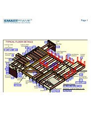
<strong>SmartForm</strong> <strong>11.7</strong> - “F” gradetimber comparisonLVL is an engineered mber product whose characteriscstrength properes are derived by in-grade tesng to AS/NZS4063. “F”” grades are assigned aer visual grading of the solidmber to the appropriate standards.There is no direct link between “F” graded mber and in-gradetested mber.Notwithstanding the above, <strong>SmartForm</strong> <strong>11.7</strong> may be used tosafely substute “F” graded material up to and including F8.Design capacies for the table are based upon the following criteria:<strong>SmartForm</strong> <strong>11.7</strong> Section properties<strong>SmartForm</strong> sizeD x B mmSelf weightkg/mRigidity EIx 10 9 Nmm 2BendingΦM kNm• Capacity reducon factor Φ = 0.85 (Primary Structural Elements other than houses table 2.5 AS 1720.1)• k 1 = 0.94 (Duraon of 5 days) AS1720.1• Full lateral restraintDesign CapacityShearΦV kN95 x 45 2.4 37.6 2.2 7.595 x 63 3.4 52.7 3.1 10.5130 x 75 5.6 160.7 6.8 17.1150 x 75 6.4 246.8 9.1 19.8<strong>SmartForm</strong> <strong>11.7</strong> Product MarkingFormwork Design ProcessThe design of formwork always starts with defining the qualityof the finished concrete surface. This is usually communicatedthrough the project documents. Surface quality is effected bythe extent to which the formwork components deflect underthe applied loadings. Physical quality and tolerances, detailedin AS 3610 tables 3.3.1 and 3.4.2 guide the formwork designerin the selecon of formface material and deflecon limits forthe framing members for soffits and wall forms. The tablesinclude the deflecon criteria for the most common classes offinish, namely: Class 3 - Maximum of 3 mm or span/270CONVENTIONAL SOFFIT FORMWORK FOR SLABSFormworkSpan tables for alternave deflecon limits are available bycontacng the SmartData Customer HelpLine on 1300 668 690or at smartdata@lling.com.auThe design aids in this design guide are confined to the selec-on of <strong>SmartForm</strong> <strong>11.7</strong> LVL members which ensure that theformwork provides the strength and rigidity necessary to meetboth structural safety and surface quality requirements. Structuralsafety is limited to the selecon of individual structuralcomponents subject to normal concrete pressures. This designguide does NOT address the structural safety of the systemthat may be subject to a wide range of abnormal and accidentalloads. Methods for developing lateral restraint, providingadequate support as well as the overall stability of thestructure are outside the scope of this publicaon.BearerPropJoistThe members in this table have been designed based upon theaddion of the “Global load factor for primary member” introducedinto AS 3610 - 1995 with Amendment 1 - 2003.JoistspanJoistspanProp spacingand BearerspanProp spacingand BearerspanFor horizontal members such as bearers and joists for soffits,both the joists and bearers have been considered primarymembers. For vercal forms, the soldiers have been consideredprimary members.<strong>SmartForm</strong> <strong>11.7</strong> Design Guide 2 Edition 2 <strong>Jan</strong> <strong>2012</strong>
<strong>SmartForm</strong> <strong>11.7</strong> Joists for Concrete Slab SoffitsMax deflecon greater of 3 mm or span/270 - Class 3Single SpanJoistspacingJoist loadwidth =JoistspacingJoistspacingNotes for use with Table1. Minimum bearing length = 45 mm atend supports. Subscript values indicateaddional bearing length requiredabove the minimum of 45 mmto achieve the stated span2. Spans in tables have been designed asper secon 4 of AS 3610-1995, includingAmendment 1:2003 for all stage 1,2 and 3 loadings. This allows for a 4.0KPa imposed load due to stackedmaterial as a stage 3 loading. This loadis considered to be addional to otherlive loads. If the project designer applieslimitaons to restrict these materialloads to a lesser amount (as specifiedin Clause 2.3(b) of AS 3610 -1995), then larger spans will beachieved.3. Since the finish quality is dependentupon a number of factors includingthe formface used and the accuracy ofthe setup, a class 3 finish cannot beguaranteed.4. For mulple spans, the design hasassumed the most conservave of 2and 3 spans and that all spans areessenally equal.5. The design has assumed that the joistsare connually restrained by thesheeng and the bearers are restrainedby the joists.6. The design tables are only suitable forhorizontal forms. For angled soffits,consult a formwork designer.Joist sizeDxB (mm)95x4595x63130x75150x75Joist sizeDxB (mm)95x4595x63130x75150x75Slab depthJoists spacing (mm)(mm) 225 300 400 450 480 600100 1900 1700 1500 1500 1400 1300150 1800 1600 1500 1400 1400 1300200 1700 1500 1400 1300 1300 1200300 1600 1400 1300 1200 1200 1100400 1500 1300 1200 1100 1100 1000600 1300 1200 1100 1000 1000 NS1000 1100 1000 NS NS NS NS100 2100 1900 1700 1700 1600 1500150 2000 1800 1600 1600 1500 1400200 1900 1700 1600 1500 1500 1400300 1800 1600 1400 1400 1400 1300400 1600 1500 1300 1300 1300 1200600 1500 1300 1200 1200 1100 11001000 1300 1200 1100 1000 1000 NS100 3100 2800 2500 2400 2400 2200150 2900 2600 2400 2300 2300 2100200 2800 2500 2300 2200 2100 2000300 2600 2300 2100 2000 2000 1800400 2400 2200 2000 1900 1900 1700600 2200 2000 1800 1700 1700 16001000 1900 1700 1600 1500 1500 1300100 3600 3200 2900 2800 2800 2600150 3400 3100 2800 2700 2600 2400200 3200 2900 2600 2500 2500 2300300 3000 2700 2400 2300 2300 2100400 2800 2500 2300 2200 2200 2000600 2500 2300 2100 2000 1900 18001000 2200 2000 1800 1700 1700 1600Continuous SpansSlab depthJoists spacing (mm)(mm) 225 300 400 450 480 600100 2300 2100 1900 1700 1700 1500150 2200 2000 1700 1600 1600 1400200 2100 1900 1600 1500 1500 1300300 1900 1700 1500 1400 1300 1100400 1800 1600 1300 1200 1200 1000600 1600 1400 1200 1100 1000 NS1000 1300 1100 NS NS NS NS100 2600 2400 2200 2100 2000 1800150 2500 2200 2000 1900 1900 1600200 2400 2100 1900 1800 1800 1500300 2200 2000 1800 1600 1600 1400400 2000 1900 1600 1500 1400 1300600 1900 1700 1400 1300 1300 11001000 1600 1300 1100 1000 1000 NS100 3800 3500 3100 3000 2900 2600150 3600 3300 3000 2800 2800 2400200 3400 3100 2800 2700 2600 2300300 3200 2900 2600 2400 2300 2100400 3000 2700 2400 2200 2100 1900600 2700 2400 2100 1900 1900 16001000 2300 2000 1700 1600 1500 1300100 4400 4000 3600 3500 3400 3000150 4200 3800 3400 3300 3100 2800200 4000 3600 3300 3100 3000 2600300 3700 3300 3000 2800 2700 2400400 3500 3100 2700 2500 2500 2200600 3100 2800 2400 2200 2100 19001000 2700 2300 1900 1800 1700 1500<strong>SmartForm</strong> <strong>11.7</strong> Design Guide 3 Edition 2 <strong>Jan</strong> <strong>2012</strong>
<strong>SmartForm</strong> <strong>11.7</strong> Bearers for Concrete Slab SoffitsMax deflecon greater of 3 mm or span/270 - Class 3Single SpanBearer sizeDxB (mm)Slab depth(mm)Bearer spacing900 1200 1500 1800 2100 2400Load areasupportedby bearersJoist span =Bearer spacing100 1400 1200 1100 1000 900 800150 1300 1100 1000 900 800 800200 1200 1100 1000 800 800 700PropsJoist span =Bearer span95x63300 1100 1000 800 800 800 700400 1000 900 800 800 700 600600 900 800 700 700 600 500Bearer span1000 700 600 500 500 5 NS NS100 2000 1800 1600 1600 1400 1200150 1900 1700 1500 1500 1300 1100200 1800 1600 1500 1400 1200 1100130x75300 1600 1400 1300 1200 1100 1000150x75Bearer sizeDxB (mm)95x63130x75150x75400 1500 1300 1300 1100 1000 900 5600 1300 1100 1100 1000 900 5 800 101000 1100 900 900 800 5 700 15 600 20100 2400 2100 1800 1600 1500 1400150 2200 1900 1700 1500 1400 1300200 2100 1800 1600 1400 1300 1200300 1900 1600 1400 1300 1200 1100 5400 1700 1500 1300 1200 1100 5 100 10600 1500 1300 1100 5 1000 10 900 15 900 151000 1200 1000 5 900 15 800 20 800 25 700 30Slab depthmm)Continuous SpansBearer spacing900 1200 1500 1800 2100 2400100 1400 1200 1100 900 800 800150 1300 1100 900 800 700 700200 1200 1000 800 700 700 700300 1100 900 700 700 600 600400 1000 700 700 600 NS NS600 800 700 NS NS NS NS1000 700 NS NS NS NS NS100 2000 1700 1500 1400 1300 1200150 1900 1600 1400 1300 1200 1100200 1800 1500 1400 1200 1000 1000300 1600 1400 1100 1000 900 800400 1500 1200 1100 1000 900 800600 1200 1000 900 800 5 NS NS1000 900 800 5 700 15 600 25 NS NS100 2300 2000 1800 1600 1500 1400150 2200 1800 1700 1500 1400 1300200 2100 1700 1600 1300 1300 1200 5300 1800 1600 1300 1200 1100 1000 15400 1700 1400 1200 1100 1000 15 900 25600 1400 1200 1000 15 900 20 800 15 800 401000 1100 5 1000 20 800 25 800 50 600 50 NSNotes for use with Table1. Minimum bearing length = 45 mm atend supports and 90 mm ia interiorsupports. Subscript values indicateaddional bearing length requiredabove the minimum of 45 or 90 mmrespecvely to achieve the stated span2. Spans in tables have been designed asper secon 4 of AS 3610-1995, includingAmendment 1:2003 for all stage 1,2 and 3 loadings. This allows for a 4.0kPa imposed load due to stacked materialas a stage 3 loading. This load isconsidered to be addional to otherlive loads. If the project designer applieslimitaons to restrict these materialloads to a lesser amount (as specifiedin Clause 2.3(b) of AS 3610 - 1995),then larger spans will be achieved.3. Since the finish quality is dependentupon a number of factors including theformface used and the accuracy of thesetup, a class 3 finish cannot be guaranteed.4. For mulple spans, the design hasassumed the most conservave of 2and 3 spans and that all spans areessenally equal.5. The design has assumed that the joistsare connually restrained by thesheeng and the bearers are restrainedby the joists.6. The design tables are only suitable forhorizontal forms. For angled soffits,consult a formwork designer.7. To sasfy the bearing requirements ofthe mber, the breadth of the bearermust be equal to or greater than thebreadth of the joists it is supporng.<strong>SmartForm</strong> <strong>11.7</strong> Design Guide 4 Edition 2 <strong>Jan</strong> <strong>2012</strong>
EXAMPLE VERTICAL FORMS USING <strong>SmartForm</strong> <strong>11.7</strong> BEARERS AND JOISTSVercal formface up to 1800 mmFormface(see table for specification)Soldierspacing300Formface specificaons (Max 1800 mm high)Plywoodconstrucon17-10-717-16-7Stress grade Orientaon *F11F14H or VH OnlySoldiers95 x 45<strong>SmartForm</strong>400 17-10-7 F17 H or V450 17-10-7 F27 H or VSee table forsoldier spacingNotes:* - H denotes face grain horizontal- V denotes face grain vercalMaximum un-factored concrete pressure - 43 KNWaler bearers2/95 x 63 <strong>SmartForm</strong>600600Tie-rodsØN t ≥ 50 kN9001800900Tie Rod spacing-1000 mm for walers connuous over 3or more e-rod supports- 800 mm for walers supported by 2 e-rods onlyTie-rodspacing300 mmmaximum300300SectionVercal formface up to 3000 mmFormface17-10-7 F17 Plywood with face grain vertical(Based up on Maximum UN-factored concretepressure of 72 KPa)Soldiers95 x 45<strong>SmartForm</strong>3006006001100Waler bearers2/95 x 63 <strong>SmartForm</strong>11003000Tie-rodØNt ≥ 66 kN10001000Tie Rod spacing- 750 mm for walers connuous over 3or more e-rod supports- 700 mm for walers supported by 2 e-rods onlyTie-rodspacing300 mmmaximum300300Section<strong>SmartForm</strong> <strong>11.7</strong> Design Guide 5 Edition 2 <strong>Jan</strong> <strong>2012</strong>
60010008507002@3004@3005@2403900Max6509008007506002004@3004@3005@240Vercal formface up to 3900 mmFormfaceSoldier bearer spacing(see sections)Waler joist overhang300 mm Maximum30030095 x 45 <strong>SmartForm</strong>Waler joists continuousover a Minimum of 3soldiersWaler joist spacing(see section)Overall heightof form 'h"'3350max2/95 x 45 <strong>SmartForm</strong>soldier bearers continuousover 2 or more spanstie rod spacing(see sections)200SectionSectionStandard vertical Forms1. The design of the vercal forms is based upon a hydrostac pressure distribuon2. Deflecons of soldiers and walers have been limited to the greater of span/270 or 3 mm complying with class 3 finish inAS 3610 - 1995. Since the finish quality is dependent upon a number of factors including the formface used and the accuracyof the setup, a class 3 finish cannot be guaranteed3. Tie bolt holes are not to be drilled through ANY of the soldier or waler members4. The distance from the top of the form to the nearest e rod must be a maximum of 650 mm5. The design of the above forms are NOT suitable for:• Grout injected concrete• Concrete pumped from below• Deep vibraon of concrete• External concrete vibraon<strong>SmartForm</strong> <strong>11.7</strong> Design Guide 6 Edition 2 <strong>Jan</strong> <strong>2012</strong>