Global Blackouts – Lessons Learned - Siemens
Global Blackouts – Lessons Learned - Siemens
Global Blackouts – Lessons Learned - Siemens

You also want an ePaper? Increase the reach of your titles
YUMPU automatically turns print PDFs into web optimized ePapers that Google loves.
www.siemens.com/energy<br />
<strong>Global</strong> <strong>Blackouts</strong> <strong>–</strong> <strong>Lessons</strong> <strong>Learned</strong><br />
Presented at<br />
POWER-GEN Europe 2005, Milan, Italy<br />
June 28 <strong>–</strong> 30, 2005<br />
Updated Version, July 2011<br />
Authors:<br />
Günther Beck, Dusan Povh,<br />
Dietmar Retzmann, Erwin Teltsch<br />
<strong>Siemens</strong> AG, Energy Sector,<br />
Power Transmission Division, Germany<br />
Answers for energy.
2 |<br />
Table of Contents<br />
0. Overview 3<br />
1. Trends in Power Systems 3<br />
2. Large <strong>Blackouts</strong> 2003 <strong>–</strong> a Review on the Events and direct Causes 6<br />
2.1 Probability of <strong>Blackouts</strong> 6<br />
2.2 The Events in North-America 7<br />
2.3 The 2003 Events in Europe 14<br />
2.4 <strong>Blackouts</strong> in other Countries 18<br />
2.5 Costs and Consequences of System Outages 18<br />
3. Elimination of Bottlenecks in Transmission <strong>–</strong> <strong>Lessons</strong> learned 19<br />
3.1 How large can Synchronous System be? 19<br />
3.2 Solutions for System Interconnection 20<br />
3.3 Elimination of Transmission Bottlenecks<br />
with HVDC and FACTS 21<br />
4. Use of HVDC and FACTS for System Enhancement 23<br />
5. Prospects of HVDC and FACTS Technologies 27<br />
6. Conclusions 27
0. Overview<br />
The growth and extension of AC systems and consequently the introduction of higher voltage<br />
levels have been driven by a fast growth of power demand over decades. Power systems have<br />
been extended by applying interconnections to the neighboring systems in order to achieve<br />
technical and economical advantages. Regional systems have been extended to national grids<br />
and later to interconnected systems with the neighboring countries. Large systems came into<br />
existence, covering parts of or even whole continents, to gain the well known advantages, e.g.<br />
the possibility to use larger and more economical power plants, reduction in reserve capacity<br />
in the systems, utilization of the most efficient energy resources, as well as to achieve an<br />
increase in system reliability. <strong>Global</strong> studies show that power consumption in the world<br />
follows the increase in population closely. In the next 20 years power demand in developing<br />
and emerging countries is expected to increase by more than 250%, in industrialized<br />
countries, however, only by 37% (<strong>Global</strong> Insight 2008, <strong>Siemens</strong> E ST MOP 10/2008).<br />
In future, in the course of deregulation and privatization, the loading of existing power<br />
systems will strongly increase, leading to bottlenecks and reliability problems. System<br />
enhancement will be essential to balance the load flow and to get more power out of the<br />
existing grid in total. Large blackouts in America and Europe confirmed clearly that the<br />
favorable close electrical coupling of the neighboring systems might also include the risk of<br />
uncontrollable cascading effects in large and heavily loaded interconnected systems.<br />
An overview of the sequence of blackout events in US/Canada and Europe is given and<br />
countermeasures for blackout prevention - “<strong>Lessons</strong> learned” - are discussed. Avoidance of<br />
loop flows, prevention of voltage collapse, elimination of stability problems in large power<br />
systems as well as the implementation of “firewalls” are presented. The benefits of HVDC<br />
(High Voltage Direct Current) and FACTS (Flexible AC Transmission Systems) for system<br />
enhancement are explained.<br />
1. Trends in Power Systems<br />
The development of electric power supply began more than one hundred years ago.<br />
Residential areas and neighboring establishments were supplied first by DC via short lines. At<br />
the end of the 19th century, however, AC transmission has been introduced utilizing higher<br />
voltages to transmit power from “remote” power stations to the consumers.<br />
| 3
4 |<br />
Large systems came into existence, covering parts of or even whole continents, to gain the<br />
well known advantages, e.g. the possibility to use larger and more economical power plants,<br />
reduction in reserve capacity in the systems, utilization of the most efficient energy resources,<br />
as well as to achieve an increase in system reliability.<br />
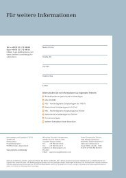
The developments in AC transmission voltages are depicted in Fig. 1.<br />
1,600<br />
kV<br />
1,400<br />
1,200<br />
1,000<br />
800<br />
600<br />
400<br />
200<br />
0<br />
1900<br />
1<br />
“Reasonable” Line Lengths:<br />
1,000 kV: over 2,000 km<br />
800 kV: up to 1,500 km<br />
500 kV: up to 1,000 km **<br />
2 3<br />
2 3<br />
1910 1920 1930 1940 1950 1960 1970 1980 1990 2000<br />
Year<br />
2010<br />
1 110 kV Lauchhammer <strong>–</strong> Riesa / Germany (1911) * China (1,000 kV Pilot Project<br />
2 220 kV Brauweiler <strong>–</strong> Hoheneck / Germany (1929) launched) and India (1,200 kV<br />
3<br />
4<br />
5<br />
287 kV Boulder Dam <strong>–</strong> Los Angeles / USA (1932)<br />
380 kV Harspranget <strong>–</strong> Halsberg / Sweden (1952)<br />
735 kV Montreal <strong>–</strong> Manicouagan / Canada (1965)<br />
in actual Planning) are currently<br />
implementing a Bulk Power UHV<br />
AC Backbone.<br />
6 1,200 kV Ekibastuz <strong>–</strong> Kokchetav / USSR (1985) ** Brazil: North-South Interconnector<br />
Source: <strong>Siemens</strong> E D SE PTI - 2008<br />
Fig. 1: Development of AC Transmission<br />
4<br />
In Western Europe 400 kV became the highest voltage level, in Far-East countries mostly<br />
550_kV and in America 550 kV and 765 kV. The 1150 kV voltage level was anticipated in<br />
the past in some countries and also some test lines have already been built. China and India<br />
for example, are currently implementing a Bulk Power UHV AC Backbone at 1,000/1,200 kV<br />
with regard to very long transmission distances between generation and load centers.<br />
However, it is not expected in the near future that AC voltage levels above 800 kV will be<br />
utilized to a greater extent in other regions of the world.<br />
The performance of power systems decrease with the size and complexity of the networks.<br />
This is related to problems with load flow, power oscillations and voltage quality. Should<br />
power be transmitted through the interconnected system over longer distances, transmission<br />
needs to be supported. This is, for example, the case in the Western European UCTE system<br />
(Fig. 2a), where the 400 kV voltage level is relatively low for large cross-border and inter-<br />
5<br />
6<br />
However, some Countries<br />
will finally “go” ≥ 1 MV *<br />
800 kV as “realistic” Standard<br />
The The “Initial “Initial Initial” Statement<br />
Statement
area power exchange. Bottlenecks are already identified (NTC - Net Transfer Capacity, Fig.<br />
2b), and for an increase in power transfer advanced solutions need to be applied. Such<br />
problems are even deepened by the deregulation of the electrical power markets, where<br />
contractual power flows no more follow the design criteria of the existing network<br />
configuration.<br />
AL MAGHREB<br />
NORDEL<br />
UCTE - 1<br />
UCTE - 2<br />
Additional problems are expected when renewable energies, such as large wind farms, have to<br />
be integrated into the system, especially when the connecting AC links are weak and when<br />
there is no sufficient reserve capacity in the neighboring system available. Fig. 3 summarizes<br />
the prospects of power system developments.<br />
<strong>Global</strong>isation/<br />
Liberalisation<br />
Privatisation<br />
Bottlenecks in<br />
Transmission<br />
Privatisation<br />
Investments in<br />
Power Privatisation Systems<br />
IPS/UPS<br />
Turkey<br />
Bottlenecks<br />
in the UCTE<br />
System<br />
… Zone 1 & 2 “resynchronized” since 10.10. 2004<br />
a)<br />
Fig. 2: European Power Systems (2004)<br />
a) Overview of the Systems<br />
b) Bottlenecks in UCTE (now CE)<br />
Deregulation - Privatization: Opening of the<br />
markets, Independent Transmission Companies<br />
ITCs, Regional Transmission Organisations RTOs<br />
Problem of uncontrolled Loop-Flows<br />
Overloading & Excess of SCC Levels<br />
System Instabilities & Outages<br />
System Enhancement & Interconnections:<br />
�� � Higher Voltage Levels<br />
�� � New Transmission Technologies<br />
�� � Renewable Energies<br />
Fig. 3: Trends in High Voltage Transmission Systems<br />
b)<br />
NTC Values<br />
for East-<br />
West Power<br />
Transfer<br />
Source: UCTE - 5 / 2003<br />
| 5
6 |<br />
Increasing part of the installed capacity will, however, be connected to the distribution levels<br />
(dispersed generation) in the future, which poses additional challenges to planning and safe<br />
operation of the systems, see Fig. 4.<br />
Today:<br />
G G<br />
Use of Dispersed Generation<br />
10-2008<br />
E T PS SL/Re<br />
Fig. 4: Prospects of Network Developments<br />
Fig. 5: Reasons for high Probability of <strong>Blackouts</strong><br />
G<br />
G<br />
G<br />
G<br />
G<br />
Tomorrow:<br />
Load Flow will be “fuzzy”<br />
2. Large <strong>Blackouts</strong> 2003 <strong>–</strong> a Review on the Events and direct Causes<br />
2.1 Probability of <strong>Blackouts</strong><br />
G<br />
G<br />
H<br />
G<br />
G<br />
H<br />
G<br />
H
Fig. 5 shows that the probability of large <strong>Blackouts</strong> is much higher than calculated by<br />
mathematical modeling, especially when the related amount of power outage is very large.<br />
The reasons for this result are indicated in the figure. This means that, when once the<br />
cascading sequence is started, it is mostly difficult or even impossible to stop it, unless the<br />
direct causes are eliminated by means of investments into the grid and by an enhanced<br />
training of the system operators for better handling of emergency situations.<br />
2.2 The Events in North-America<br />
The Blackout sequence started on august 14, 2003, around noon. Reactive power and voltage<br />
problems have been reported, but not major ones. Fig. 6 shows the results of a study on the<br />
related transmission systems, which was published in May, one year earlier. It can be seen,<br />
that load flow in the system is not well matching the design criteria, ref. to the “hot lines”,<br />
shown in red color. On the upper right-hand side of the figure, one of the later Blackout<br />
events with “giant” loop flows is attached, which happened just in the same area under<br />
investigation one year before.<br />
Giant Loop Flows<br />
2.2 - 4.8 GW<br />
*<br />
System Enhancement necessary !<br />
Problems only in the<br />
synchronously<br />
interconnected<br />
Systems<br />
Source: ITC 8/2003 <strong>–</strong> “Blackout”<br />
Source: National Transmission Grid Study; U.S. DOE<br />
5/2002 <strong>–</strong> “Preview”<br />
*<br />
Fig. 6: Comparison of Study Results 2002 with the real Blackout 2003 Scenario<br />
PTDF = Power Transfer Distribution Factor<br />
* PTDF = Power Transfer Distribution Factor<br />
In the following, a summary of the events is given and the key-findings are discussed.<br />
Fig. 7 shows that there was in fact plenty of time (1.5 hours) for remedial actions, before the<br />
power outage reached a larger amount (1.8 GW).<br />
| 7
8 |<br />
Lack of 1.8 GW<br />
Generation<br />
Source: Blackout Summary, U.S./Canada<br />
Power Outage Task Force 9-12-2003<br />
Fig. 7: The US Blackout <strong>–</strong> Events 1-3<br />
It was reported in the “Blackout Summary of the Power Outage Task Force”, that a lack of<br />
communication and exchange of information among the operators was a major cause of the<br />
cascade of events. A server computer outage, as indicated in Fig. 8, was contributing to that.<br />
It led to a significant un-awareness of the upcoming risk in the system, although there was<br />
sufficient time for actions, such as splitting the system and trip of selected loads.<br />
Reported Reasons:<br />
Brush-Fire under the Line<br />
(Source: U.S. DOE Timeline 09-12-<br />
2003)<br />
Starting around 2:14, FirstEnergy<br />
lost a number of EMS functions<br />
along with Primary & Backup<br />
Server Computer<br />
(Source: EURELECTRIC 06-2004)<br />
Fig. 8: Event 4 <strong>–</strong> plus major Computer Failures at 2:14
Around 3 to 4 hours after the first event (ref. to Fig. 7) the situation became in fact critical, as<br />
indicated in Fig. 9.<br />
Outage of Line (5) was not<br />
reported to the Dispatching Center<br />
Line (6) contacted a tree* and tripped<br />
*Source: NERC-Technical<br />
Analysis 07-2004<br />
Fig. 9: Events 5-7 <strong>–</strong> From now on a critical Situation<br />
At 4:06, a wrong relay operation (Sammis-Star Line, Fig. 10) initiated the final cascade, and<br />
shortly after, at 4:14, the “point of no return” was reached, as shown in Fig. 11. This event<br />
initiated huge loop flows across several states and the beginning of voltage collapse. Fig. 12<br />
depicts such a situation with a huge loop of 2.8 GW. This led to further disconnections of<br />
lines and large amounts of generation capacity, with significant voltage and frequency<br />
fluctuations, up and down. Voltage collapse and the final Blackout were the consequence.<br />
In Fig. 13 a view on the affected area is given (part a) and the satellite photos show the<br />
situation before and after the events (part b). The figure indicates that the Québec system in<br />
Canada was not affected due to its DC interconnection to US, whereas Ontario (synchronous<br />
interconnection) was fully “joining” the cascade.<br />
Wrong Operation of a Protection Relay<br />
This was the main “Trigger” of<br />
the final Blackout Sequence<br />
(Source: EURELECTRIC 06-2004)<br />
Fig. 10: Event 8 and the decisive Event 9<br />
| 9
10 |<br />
4:09 PM - “Point of no Return”<br />
(Source: ITC 08-2003 <strong>–</strong> “Blackout”)<br />
Fig. 11: Events 10-12 <strong>–</strong> Begin of Voltage Decline<br />
Fig. 12: Event 18 <strong>–</strong> 30 s to Blackout<br />
The reasons why Québec “survived” the cascade are very clear:<br />
Giant Loop<br />
Flow 2.8 GW<br />
� Québec´s major Interconnections to the affected Areas are DC-<br />
Links<br />
� These DC-Links are like a Firewall against Cascading Events<br />
� They split the System at the right Point on the right Time,<br />
whenever required<br />
� Therefore, Québec was “saved”<br />
� Furthermore, the DCs assisted the US-System Restoration by<br />
means of “Power Injection”
a)<br />
Blackout: a large Area is out of Supply<br />
Fig. 13: The Blackout Area a) and a Satellite View b), before and after the Outage<br />
Fig. 14 and Fig. 15 depict a view of the systems dynamics during the cascade. It can be seen<br />
that the number of disconnections and fluctuations in power and frequency where in fact<br />
huge. In total, an amount of about 62 GW customer loads were lost, and about 50 million<br />
people in seven states were out of supply. However, 50 GW loads were reconnected within 16<br />
hours.<br />
Source: Cigré Paris Session 2004<br />
Fig. 14: Recordings from HydroOne <strong>–</strong> from 16:05 to 16:12<br />
However, some Islands still have local Supply<br />
b)<br />
Before the Blackout Source: EPRI 2003<br />
Events and GWs<br />
Québec´s HVDCs assist<br />
in Power Supply and<br />
System Restoration<br />
| 11
12 |<br />
� f = + 3.2 / - 1.5 Hz ≈ 5 Hz in 18 s<br />
Fig. 15: Frequency Recordings from New York <strong>–</strong> 16:10:34 to 16:11:39<br />
Fig. 15 shows that such large frequency deviations must in fact lead to generator tripping. On<br />
the other hand, if more power would be fed in by HVDC from surrounding parts of the grid,<br />
such a cascade could have been avoided, because HVDC and in general power electronics<br />
(e.g. FACTS for voltage support) can withstand a wide range of frequency variations, e.g.<br />
even +/-5 Hz are usually no problem for such controllers.<br />
The primary root causes of the US-Canada events can be summarized as follows:<br />
A brief Summary of the “primary” Root Causes:<br />
� Lack of Investments into the Grids (high Cost-Pressure for the<br />
Asset-Owners due to Deregulation), leading to Bottlenecks in<br />
Transmission<br />
� Lack of Communication among the Operators<br />
� Need for more Regulatory Works (Rules, Grid Code etc.) for the<br />
Operation of Transmission Systems and Power Plants in Case<br />
of Cascading Events<br />
� Weak Points in System Protection, Energy and Demand Side<br />
Management - EMS, DSM<br />
Generators<br />
don’t like such<br />
Frequency<br />
“Excursions” <strong>–</strong><br />
for HVDC and<br />
FACTS: they are<br />
no Problem<br />
The conclusions of the Outage Task Force final report are depicted in Fig. 16. Fig. 17 shows,<br />
how the relay tripping at Sammis-Star Line could have been avoided by means of modern<br />
numerical protection relays, and Fig. 18 gives an example for avoiding voltage collapse by<br />
use of reactive (FACTS) and active power injection (HVDC).
Source: US-Canada Blackout Final Report April 2004<br />
System Enhancement & Elimination of Bottlenecks<br />
● On-Line Monitoring and Real-Time Security Assessment<br />
● Increase of Reserve Capacity<br />
Fig. 16: Conclusions of the US-Canada Blackout Final Report April 2004<br />
X/Ohm<br />
100<br />
50<br />
x<br />
x<br />
Conventional (not digital) Relays lead to unselective<br />
Tripping under high Load Conditions<br />
Sammis-Star: unselective Trip<br />
50 100 R/Ohm<br />
Load Flow <strong>–</strong> Steady State<br />
The Solution …<br />
Digital Protection: T-Bone or MHO-Characteristic with<br />
incorporated Load Blocking<br />
Fig. 17: Avoidance of Outages through Investments in new Technologies <strong>–</strong><br />
Example of System Protection<br />
| 13
14 |<br />
No Support of Recovery<br />
2.3 The 2003 Events in Europe<br />
These events can be summarized as follows:<br />
Great Britain (August 28):<br />
� 1 Transformer out of service due to Buchholz Alarm and<br />
a wrong Protection Relay Setting. However, only a<br />
limited Area (South London) was affected<br />
Denmark-Sweden (September 23):<br />
� A large Collapse in the Synchronous Area due to<br />
Power Station Outages in Combination with a double<br />
Busbar Fault (storms and wrong “construction”)<br />
Italy (September 28):<br />
Reactive Power and<br />
Active Power Injection<br />
Blackout No Blackout<br />
Voltage remains low Voltage recovers<br />
Fig. 18: Avoidance of Voltage Collapse by means of Power Electronics with fast<br />
__Reactive and Active Power Injection<br />
� Outage of 2 major Transmission Lines; Overload on the __<br />
remaining Lines <strong>–</strong> Full Blackout <strong>–</strong> very similar to the US-<br />
Canada Event<br />
In Great Britain, shortly after the US-Canadian events, a transformer was taken out of service<br />
due to a wrong Buchholz alarm in a transformer located in the City of London. During this<br />
operation, an adjacent cable section was tripped due to a wrong protection relay setting, which<br />
led to power outage on a limited area (Fig. 19), see the shaded region.<br />
About one month later a Blackout occurred in the synchronous area of Denmark-Sweden too,<br />
due to a power station outage and a double busbar fault (wrong construction plus strong<br />
winds), which is really a very seldom event in power systems, and this was followed by an
other power plant outage. A large part of the synchronous area lost its supply for half a day<br />
(see Fig. 20), and even the parliament in Copenhagen was blacked-out.<br />
3<br />
1 Transformer Buchholz Alarm<br />
2 Disconnection of the first 275 kV Cable Section to isolate the Transformer<br />
3 Wrong Protection Setting ( Disconnection of the 2nd 2 Disconnection of the first 275 kV Cable Section to isolate the Transformer<br />
3 Wrong Protection Setting ( Disconnection of the 2 Cable Section<br />
nd 3 Wrong Protection Setting ( Disconnection of the 2 Cable Section<br />
nd Cable Section<br />
Fig. 19: Causes and Events of the Outage in Great Britain, August 2003<br />
The Blackout Area is quite large !<br />
Source: Cigré Paris Session 2004<br />
1<br />
2<br />
Loss of Supply for 410,000 Customers in South London<br />
1 12.30 Outage of NPP<br />
1200 MW (faulty Valve)<br />
2 12.35 Double Busbar Fault<br />
3 Outage of 2 NPP 1800 MW<br />
23.9.03<br />
Fig. 20: The Blackout in Denmark-Sweden, Sept. 2003<br />
Source: NGC Investigation Report 10-10-2003<br />
The Consequences: Power Oscillations, Load-Shedding,<br />
Voltage Collapse - Restoration of the System at 19.05<br />
Source: EURELECTRIC External Reports 2003<br />
3<br />
2<br />
Oskarshamm<br />
1<br />
| 15
16 |<br />
The “follow-up” was then done by Italy, shortly after Denmark-Sweden, only 5 days later.<br />
This event was in fact a huge Blackout, similar to the events in US-Canada, ref. to Fig. 21.<br />
Overload on two 400 kV Lines from<br />
France to Italy and Trip of both<br />
Outage of two inner-Swiss 400 kV Lines<br />
Full Blackout in Italy, 9-28-2003,<br />
early in the Morning. Approximately<br />
50 m People were without<br />
Electricity Supply. Luckily, this<br />
happened on Sunday.<br />
Fig. 21: Large Blackout in Italy, very similar to the US-Canada event<br />
20 min. after the 1st Line Trip:<br />
Loss of a 2nd 20 min. after the 1<br />
Line … followed by<br />
a very fast cascading Sequence<br />
st Line Trip:<br />
Loss of a 2nd Line … followed by<br />
a very fast cascading Sequence<br />
The Italian Blackout was initiated by a line trip in Switzerland. Reconnection of the line after<br />
the fault was not possible due to a too large phase angle difference (about 60 degrees, leading<br />
to blocking of the Synchro-Check device). 20 min later a second line tripped, followed by a<br />
fast trip-sequence of all interconnecting lines to Italy due to overload (Fig. 21). During the<br />
sequence the frequency in Italy ramped down for 2.5 Hz within 2.5 min, and the whole<br />
country blacked-out. Several reasons were reported: wrong actions of the operators in Italy<br />
(insufficient load rejection) and a too high power import from the neighboring countries in<br />
general. In deed, during the night from Saturday to Sunday, the scheduled power import was<br />
6.4 GW, this is 24 % of the total consumption at that time (27 GW; EURELECTRIC Task<br />
Force Final Report 06-2004). In addition, the real power import was still higher (6.7 GW;<br />
possibly due to country-wide celebration of what is known as “White Night”).<br />
In Fig. 22 the sequence of events is depicted and Table 1 summarizes the reasons for the<br />
Italian Blackout and the countermeasures to be taken. It is one of the key-consequences of<br />
deregulation that the power transfer across the systems is nowadays much more wide-spread<br />
and fluctuating than initially designed by the system planners. The system elements are going<br />
to be loaded up to their limits with risk for loosing the n-1 reliability criteria. System<br />
enhancement will be essential in the future, in Europe too.
Fig. 22: The Sequence of Events in Italy <strong>–</strong> UCTE Final Italian Blackout Press<br />
Release and Interim Report 10-27-2003<br />
<strong>Lessons</strong> <strong>Learned</strong>:<br />
Power Systems have not been designed for “Wide-Area”<br />
Energy Trading with load patterns varying daily<br />
A Key-Issue in many Power Systems today:<br />
The Grids are “close to their Limits”<br />
Source: UCTE Interim Report 10-27-2003<br />
Table 1: Summary of Root Causes for the Italian Blackout and Action Plan<br />
UCTE Interim Report 10-27-2003<br />
| 17
18 |<br />
2.4 <strong>Blackouts</strong> in other Countries<br />
In addition to the outages mentioned above, some other <strong>Blackouts</strong> have been reported:<br />
EURELECTRIC Task Force Report 6-2004:<br />
� Spain, 12-17-2001: extremely cold weather conditions (high loads)<br />
�2 hours of emergency conditions in the Spanish Grid <strong>–</strong> saved by 500 MW load<br />
shedding<br />
� Denmark, 12-28-2002: loss of supply for 1 million customers<br />
�Reasons: 2 independent protection relay errors. Supply fully recovered in 3<br />
hours<br />
� Austria, 8-27-2003: outage of Krsko Nuclear Power Plant in Slovenia, during<br />
tests,<br />
�followed by transmission line trip Hungary Croatia (welded relay contact)<br />
�Automatic disconnection device in Austria triggered, followed by severe crossboarder<br />
load changes. Full system restoration within 2 hours, no loss of supply<br />
… and some more (Cigré 2004 - 2008, Paris Sessions)<br />
Various Reasons: e.g. load-flow problems; breaker explosion (Iran); tornados, ice and<br />
snow storms (Europe, China), double-circuit line outage (Germany)<br />
The reasons for these events are similar to the previously mentioned cases: overloads, maloperation<br />
of protection and equipment as well as human errors. The examples underline the<br />
necessity of investments into the grids.<br />
2.5 Costs and Consequences of System Outages<br />
The electric power supply is essential for life of a society, like the blood in the body. Without<br />
power supply there are devastating consequences for daily life: breakdown of public<br />
transportation systems, traffic jams, computer outages as well as still-stand in factories,<br />
shopping malls, hospitals etc.<br />
The Costs depend on the Type of “Loads”:<br />
� Short Outages for Industrial Customers: 1,000 €/kWh<br />
→ very high Costs<br />
� Very long Outages (more than 24 hours) for residential<br />
Consumers: 5 €/kWh<br />
� Outages less than 24 hours for residential Consumers:<br />
1 €/kWh<br />
Note: “Typical” Long-Distance Transmission<br />
Costs are ≈ 1-2 € Cents/kWh !<br />
Table 2: Costs of <strong>Blackouts</strong> are very high (Source: EURELECTRIC Task<br />
Force Final Report 06-2004)
UPS (Uninterruptible Power Supplies) are available only for very few specific applications<br />
for cost reasons. As a result, the consequences of large <strong>Blackouts</strong> can be dramatic: very high<br />
economic losses and very high costs, depending on duration of the outage and kind of loads,<br />
ref. to Table 2.<br />
3. Elimination of Bottlenecks in Transmission <strong>–</strong> <strong>Lessons</strong> learned<br />
3.1 How large can Synchronous System be?<br />
In theory, by using controlled and fixed series compensation, a transmission system can be<br />
extremely large, e.g. 6,000 km, ref. to Fig. 23. However, at such lengths, there will be major<br />
stability constraints, even when using a high transmission voltage and active damping features<br />
on the transmission line.<br />
Degree of Series Compensation<br />
2 Lines<br />
3 Lines<br />
Controlled Series Compensation<br />
Transmission Length (x 1,000 km)<br />
Fig. 23: Limits of Long Distance AC Transmission<br />
Example: 765 kV Transmission<br />
Series Compensation<br />
Fixed Controlled<br />
Fixed Parallel Compensation<br />
Fixed Series Compensation These Extensions are a Matter of Theory. In<br />
Practice, large Stability Problems will occur.<br />
Source: <strong>Siemens</strong> E D SE PTI - 2002<br />
In Fig. 24 the basic limitations of such very large power systems are depicted, for both AC<br />
long distance transmission and for interconnected power systems. The two tables shows the<br />
basic constraints and problems of very large systems, and the right hand figure compares<br />
efforts (=costs) for system adaptation versus the benefits (e.g. wide-area power trading,<br />
sharing of reserve capacity), depending on the system size.<br />
It can be seen, that the best solution is a “medium” sized grid with optimal cost-toperformance<br />
ratio.<br />
| 19
20 |<br />
Limitations of large AC Systems<br />
o Voltage Stability<br />
Interconnected Systems<br />
o Load-Flow Problems (Manage-<br />
Long-Distance Transmission<br />
ment of Congestion required)<br />
Systems<br />
o Frequency Control<br />
o Voltage Stability<br />
o Reactive Power Problems o Oscillation Stability<br />
o Steady-state Stability<br />
o Inter-Area Oscillations<br />
o Blackout Risk due to<br />
o Transient Stability<br />
Cascading Effects<br />
o Interactions between the Power<br />
o Subsynchronous Oscillations Systems in Terms of Physics<br />
Fig. 24: How large can a synchronous System be ?<br />
3.2 Solutions for System Interconnection<br />
There are basically three possibilities to interconnect power systems, ref. to Fig. 25:<br />
� synchronous interconnection (AC Solution)<br />
Benefits,<br />
Efforts<br />
Benefits<br />
� asynchronous interconnection using HVDC (DC Solution)<br />
o HVDC Back-to-Back (without DC-Line)<br />
o HVDC Long-Distance Transmission with DC Line<br />
� hybrid synchronous interconnection (Hybrid Solution)<br />
Cost-to-Performance Ratio<br />
Optimum<br />
Advantages of<br />
interconnected interconnected Operation<br />
Operation<br />
Efforts<br />
Size of interconnected Grid<br />
When the Synchronous System is very large <strong>–</strong> Advantages diminish<br />
System 1 System 2<br />
AC Interconnection:<br />
many Lines “from the Beginning”,<br />
for Stability Reasons<br />
DC Interconnection:<br />
1 Link sufficient for stable<br />
Interconnection<br />
Hybrid AC/DC Interconnection:<br />
The flexible synchronous Solution<br />
Fig. 25: Alternatives of Power System Interconnections<br />
a) a) Back-to-Back Solution<br />
b) b) HVDC Long Distance Long-Distance SolutionTransmission<br />
By using DC for interconnection of power systems, many benefits can be achieved: with DC,<br />
an easy staging is possible (one link is already stable), whereas an AC-Interconnection must<br />
a)<br />
b)
e strong from the beginning on for stability reasons (many lines in parallel), even if the<br />
demand on power exchange were significantly smaller than the sum of the transmission lines<br />
capacity. The Hybrid Solution is the preferred solution in countries with strongly growing<br />
networks due to high energy demand: e.g. in Brazil (from Itaipu to Sao Paulo) and in China.<br />
The Hybrid Solution offers specific control functions to stabilize parallel AC links: power<br />
oscillation damping for inter-area oscillations and voltage control.<br />
Fig. 26 shows long distance point-to-point interconnection with DC and AC in comparison<br />
with AC transmission through interconnected synchronous subsystems, which is the today’s<br />
solution in UCTE. In Fig. 26 B), series compensation is used to increase the transmission<br />
capacity of the long AC line.<br />
A)<br />
B)<br />
C)<br />
Subs.<br />
Subs. Subs.<br />
A) HVDC Long Distance Transmission<br />
Point-to-Point Connection<br />
B) Long Distance AC Transmission<br />
C) AC Transmission through interconnected Power Systems<br />
Fig. 26: Network Configurations for Long Distance Transmission<br />
In case of long distance AC transmission by means of controlled series compensation (mostly<br />
in combination with some fixed series compensation) an active stability function can be<br />
achieved, similar to the DC or Hybrid Solution. Examples are presented in the next section.<br />
3.3 Elimination of Transmission Bottlenecks with HVDC and FACTS<br />
Fig. 27 depicts the basic ideas of transmission enhancement by means of HVDC and FACTS<br />
(ref. to the system in Fig. 6). Depending on the grid structure, there are four basic cases:<br />
� load displacement by means of impedance variation (series compensation, FACTS)<br />
� load-flow control with HVDC (or FACTS with a combination of series and shunt<br />
controllers)<br />
| 21
22 |<br />
� voltage collapse: reactive/active power injection (with HVDC/FACTS, ref. to Fig. 18)<br />
� excess of allowed short-circuit level due to new power plants: short-circuit current<br />
limitation (FACTS/HVDC)<br />
*<br />
Load Displacement by Series Compensation<br />
Fig. 27: Elimination of Bottlenecks in Transmission - Prevention of<br />
Overloads and Outages<br />
The approach of system enhancement, as shown in Fig. 27, is based on the transmission<br />
equation in Fig. 28:<br />
V 1<br />
, �� 1<br />
P =<br />
Series Compensation<br />
V 1 V 2<br />
Load Management by HVDC<br />
X<br />
Parallel Compensation<br />
Fig. 28: Power Transmission - The basic Equation<br />
X<br />
Fault-Current Limitation for connecting new Power Plants<br />
SVC & HVDC for Voltage Collapse Prevention<br />
P<br />
The FACTS & HVDC “Application Guide”<br />
Using FACTS for reactive power compensation the impedances and voltages of the system<br />
can be influenced: By adding a series capacitor (fixed or controlled) into the line its<br />
impedance X can be reduced or modulated (for power oscillation damping, ref. to the<br />
equation) and with FACTS parallel compensation the voltage can be stabilized (at constant<br />
values, or modulated for damping of oscillations). The transmission angle can be influenced<br />
V 2<br />
, �� 2<br />
G ~ G ~<br />
sin sin (� (� (� ( 1 - �� � 2 )<br />
* PTDF = Power Transfer Distribution Factor<br />
* PTDF = Power Transfer Distribution Factor<br />
* PTDF = Power Transfer Distribution Factor<br />
* PTDF = Power Transfer Distribution Factor<br />
Power-Flow Control<br />
Each of these Parameters can be used for Load-<br />
Flow Control and Power Oscillation Damping
y a power-flow controller, e.g. HVDC Back-to-Back. These methods are explained in more<br />
details in Fig. 29 and 30.<br />
Fig. 29: FACTS for<br />
Reactive Power Compensation<br />
G ~<br />
Slow Functions<br />
L and C<br />
Benefits of<br />
HVDC in a<br />
synchronous<br />
AC System<br />
I1<br />
V1 V2<br />
Q1<br />
Fault-Current<br />
Blocking<br />
P<br />
�� �� and ��<br />
��<br />
Fast Functions<br />
Q2<br />
Power & Voltage Control<br />
Fault-Current Blocking<br />
I2<br />
Power-Flow Control<br />
P<br />
P<br />
C C <<br />
<<br />
~ 1/X<br />
1/X<br />
L L ><br />
Section of a Transmission Line<br />
Fig. 30 shows, that HVDC is well suitable also for short-circuit current limitation (fault<br />
current blocking). In addition to this, it acts like an “automatic” Firewall in case of cascading<br />
events by fast decoupling the systems during faults and immediate restart of power flow after<br />
the fault (AC links need time consuming re-synchronization, which can take many hours in<br />
case of large system interconnections). Alongside its main function of power-flow control, the<br />
HVDC incorporates also voltage control (by reactive power injection) for both sides of the<br />
system. It decouples the transmission equation by forcing the power to flow in a similar way,<br />
as the well known phase-shifting transformer, however, much faster and independent from the<br />
frequencies and angles of the two coupled systems.<br />
4. Use of HVDC and FACTS for System Enhancement<br />
Series<br />
Compensation<br />
Voltage<br />
Control<br />
C C ><br />
><br />
Parallel<br />
Compensation<br />
Fig. 31 gives an example of a project in Virginia Smith, USA with HVDC control, including<br />
power oscillation damping features. The left part of Fig. 31 shows the network in the area<br />
around the HVDC converter station, which is coupling two asynchronous operated grids. For<br />
the given fault, a critical stability situation arises in which one of the generators falls out of<br />
X<br />
G ~<br />
Slow Functions<br />
L and C<br />
The Firewall<br />
for Blackout<br />
Prevention<br />
V<br />
V<br />
L L <<br />
Fig. 30: Benefits of HVDC -<br />
it makes Power flow<br />
| 23
24 |<br />
step, see the left section of the recordings. By means of the HVDC control facilities the power<br />
flow can be modulated very effectively to stabilize the system, consequently avoiding<br />
generator tripping. Simulations and site tests have confirmed these results.<br />
West System (2) East System (1)<br />
G<br />
U 2 U 1<br />
115 kV<br />
230 kV<br />
345 kV<br />
�G �G<br />
without<br />
POD<br />
with HVDC-POD<br />
active Power Transmission H 1MT / Re 09-2006 Division 1<br />
Fig. 31: Interconnection of Separated Grids in USA, Voltage Control and Damping<br />
of Power Oscillations - HVDC B2B - Virginia Smith Converter Station<br />
The Transmission System:<br />
Harker: 2 SVCs<br />
Increase in Transmission Capacity<br />
Prevention of Outages<br />
Results of Dynamic<br />
System Tests:<br />
a) No SVC connected<br />
b) Both SVCs in<br />
Voltage Control Mode<br />
c) Both SVCs in Power<br />
Oscillation Damping<br />
Mode<br />
Benefits<br />
Fig. 32: Europe, UK goes ahead with FACTS - 27 SVCs in the Grid<br />
Example Harker Substation - 2 parallel SVCs
In Great Britain, in the course of deregulation, new power stations where installed in the north<br />
of the country, remote from the southern load centers, and some of the existing power stations<br />
in the south were shut down due to environmental constraints and for economic reasons, see<br />
Fig. 32, left side. To strengthen the transmission system, a total number of 27 SVC have been<br />
installed, because there was no right of way for new lines or higher transmission voltage<br />
levels. Fig. 32 c) shows the very effective power oscillation damping (main control function)<br />
with two of these SVCs, installed in Harker Substation in a parallel configuration.<br />
0 MW<br />
PLINE PLINE PLINE PLINE<br />
-880 MW<br />
50 ��<br />
��<br />
ZTCSC ZTCSC ZTCSC ZTCSC<br />
0 ��<br />
��<br />
1000 km Line<br />
TCSC TCSC<br />
TCSC 5 5<br />
5 FSCs FSCs<br />
FSCs TCSC<br />
TCSC<br />
No TCSC - System instable -<br />
Line Trip after 70 s<br />
5s/Div<br />
2 TCSCs - Redundant<br />
Job sharing<br />
0 MW<br />
PLINE PLINE PLINE PLINE PLINE<br />
-880 MW<br />
50 ��<br />
��<br />
�<br />
ZTCSC ZTCSC ZTCSC ZTCSC ZTCSC<br />
0 ��<br />
��<br />
�<br />
1 TCSC - System stable<br />
0 MW<br />
P LINE<br />
-880 MW<br />
Fig. 33: 500 kV TCSC Furnas/Brazil <strong>–</strong> Essential for Transmission<br />
In Fig. 33 it is shown, how problems with large inter-area oscillations have been solved in the<br />
Brazilian System. In the Brazilian grid, the situation is critical because of a very long<br />
transmission distance between the interconnected systems: a 1,000 km 500 kV AC<br />
interconnection between North and South systems has been implemented. In the<br />
interconnection two TCSC devices were installed at both ends of the line which damp the<br />
inherent oscillations that occur between the systems. Additionally, 5 FSCs were necessary to<br />
reduce the transmission angle. The recordings from on-site tests show that the interconnection<br />
is unstable without the damping function of TCSC. If only one TCSC is in operation, the<br />
interconnection becomes already stable, and with both devices acting the inter-area<br />
oscillations are quite well damped, and redundancy is provided. From site experience it has<br />
been reported that under increased load conditions, the TCSC damping function is activated<br />
50 ��<br />
��<br />
ZTCSC ZTCSC ZTCSC ZTCSC<br />
0 ��<br />
��<br />
5s/Div<br />
5s/Div<br />
| 25
26 |<br />
up to several hundred times per day, thus saving power transmission and keeping the return<br />
on investments constantly “running”.<br />
Fig. 34 a) shows an example of the Western European system: 500 MW should be transported<br />
from Hungary to Slovenia. It can be seen that the power flow is spread widely through the<br />
neighboring systems. Only a limited amount of power is flowing directly to the target<br />
location. Using a power electronic device for power-flow control, e.g. HVDC Back-to-Back<br />
as “GPFC” (Grid Power Flow Controller), the power exchange between the two countries can<br />
be improved significantly.<br />
Uncontrolled Load Flow<br />
DE<br />
Source: E D<br />
SE PTI 1998<br />
Control of Load Flow<br />
CZ<br />
Significant Increase in<br />
Power Transfer<br />
Fig. 34 a): Load-Flow Improvement with Power-Flow Controller<br />
3 ~<br />
Loads<br />
400 MW<br />
Power- Flow<br />
Controller<br />
DE<br />
360 km<br />
CZ<br />
- 100%<br />
Power-Flow Controller<br />
Benefits:<br />
Direction of Load Flow<br />
Basis for<br />
Power Purchase Contracts<br />
FACTS: 84 % <strong>–</strong> UPFC<br />
HVDC: 100 % <strong>–</strong> B2B<br />
A B<br />
200 MW<br />
200 MW<br />
… quite Easy<br />
Restoration of the initial Power Flow <strong>–</strong> from A to B<br />
Fig. 34 b): Elimination of Loop Flows by means of Power-Flow Controller<br />
Loads<br />
3 ~
In a similar way, as shown in Fig. 34 b), power loop flows (ref. to Fig. 6 and 12) across the<br />
interconnections between two systems, caused by the installation of a new power station<br />
(shown in red color) in grid B, can be eliminated by means of a Power Flow Controller.<br />
5. Prospects of HVDC and FACTS Technologies<br />
Since the 60s of the last century, HVDC and FACTS have been developed to a viable<br />
technology with high power ratings. From the first small DC and AC "mini networks", at the<br />
end of the 19th century, there are now systems available, which can transmit 3 <strong>–</strong> 7,2 GW over<br />
large distances with only one bipolar DC transmission: 1,000 - 3,000 km or more are feasible<br />
with overhead lines. With submarine cables, transmission levels of up to 600 <strong>–</strong> 1,000 MW and<br />
distances of nearly 600 km have already been attained, and projects with cable transmission<br />
lengths of up to 1,000 km are in the stage of feasibility studies. As a Multiterminal System,<br />
HVDC can also be connected at several points with the surrounding three-phase AC network.<br />
FACTS, based on power electronics, have been developed to improve the performance of<br />
weak AC Systems and for long distance AC transmission. FACTS can, however, contribute to<br />
solve also technical problems in the interconnected power systems. Excellent operating<br />
experiences are available worldwide and the technology became mature and reliable. Rating<br />
of SVCs can go up to 800 MVAr; the world’s biggest FACTS project with series<br />
compensation (TCSC/FSC) is at Purnea and Gorakhpur in India at a total rating of 1.7 GVAr.<br />
Recent developments are HVDC PLUS and SVC PLUS, which use innovative Modular<br />
Multilevel Converter technology (MMC) for highly efficient power transmission and reactive<br />
power compensation.<br />
6. Conclusions<br />
Deregulation in Power Industry will be generally accepted worldwide. Priorities in future<br />
developments will be given to low costs at still adequate technical quality and reliability.<br />
Environmental constraints will also play an important role. The loading of existing power<br />
systems will further increase, leading to bottlenecks and reliability problems. As a<br />
consequence of “lessons learned” from the large <strong>Blackouts</strong> in 2003, FACTS and HVDC will<br />
play an important role for the system developments, leading to hybrid AC/DC systems with<br />
better controllability of the power flows and to assist in prevention of cascading disturbances.<br />
| 27
Published by and copyright © 2011:<br />
<strong>Siemens</strong> AG<br />
Energy Sector<br />
Freyeslebenstrasse 1<br />
91058 Erlangen, Germany<br />
<strong>Siemens</strong> AG<br />
Energy Sector<br />
Power Transmission Division<br />
Power Transmission Solutions<br />
Freyeslebenstrasse 1<br />
91058 Erlangen, Germany<br />
www.siemens.com/energy/hvdc<br />
For more information, please contact<br />
our Customer Support Center.<br />
Phone: +49 180/524 70 00<br />
Fax: +49 180/524 24 71<br />
(Charges depending on provider)<br />
E-mail: support.energy@siemens.com<br />
Power Transmission Division<br />
Order No. E50001-G610-A128-X-4A00 | Printed in Germany |<br />
Dispo 30003 | c4bs No. 7805 |<br />
TH 150-110812 | BR | 472543 | SD | 08112.0<br />
Printed on elementary chlorine-free bleached paper.<br />
All rights reserved.<br />
Trademarks mentioned in this document are<br />
the property of <strong>Siemens</strong> AG, its affiliates,<br />
or their respective owners.<br />
Subject to change without prior notice.<br />
The information in this document contains<br />
general descriptions of the technical options<br />
available, which may not apply in all cases.<br />
The required technical options should therefore<br />
be specified in the contract.