HFM-401/405 - Teledyne Hastings Instruments
HFM-401/405 - Teledyne Hastings Instruments HFM-401/405 - Teledyne Hastings Instruments
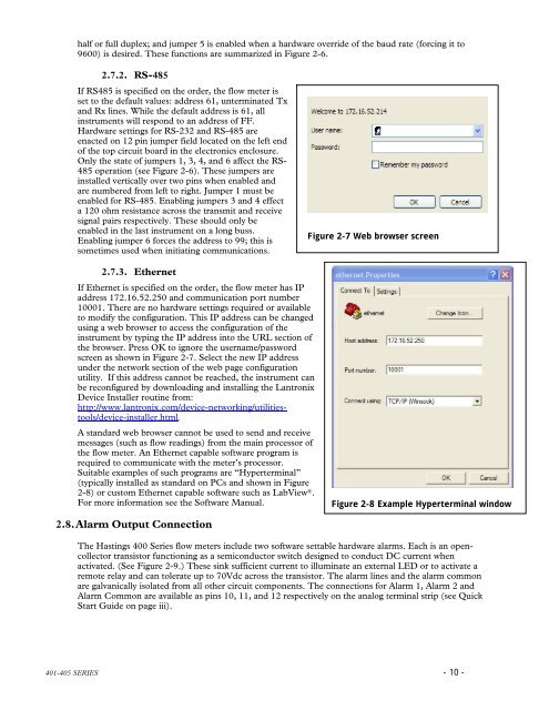
half or full duplex; and jumper 5 is enabled when a hardware override of the baud rate (forcing it to9600) is desired. These functions are summarized in Figure 2-6.2.7.2. RS-485If RS485 is specified on the order, the flow meter isset to the default values: address 61, unterminated Txand Rx lines. While the default address is 61, allinstruments will respond to an address of FF.Hardware settings for RS-232 and RS-485 areenacted on 12 pin jumper field located on the left endof the top circuit board in the electronics enclosure.Only the state of jumpers 1, 3, 4, and 6 affect the RS-485 operation (see Figure 2-6). These jumpers areinstalled vertically over two pins when enabled andare numbered from left to right. Jumper 1 must beenabled for RS-485. Enabling jumpers 3 and 4 effecta 120 ohm resistance across the transmit and receivesignal pairs respectively. These should only beenabled in the last instrument on a long buss.Enabling jumper 6 forces the address to 99; this issometimes used when initiating communications.Figure 2-7 Web browser screen2.7.3. EthernetIf Ethernet is specified on the order, the flow meter has IPaddress 172.16.52.250 and communication port number10001. There are no hardware settings required or availableto modify the configuration. This IP address can be changedusing a web browser to access the configuration of theinstrument by typing the IP address into the URL section ofthe browser. Press OK to ignore the username/passwordscreen as shown in Figure 2-7. Select the new IP addressunder the network section of the web page configurationutility. If this address cannot be reached, the instrument canbe reconfigured by downloading and installing the LantronixDevice Installer routine from:http://www.lantronix.com/device-networking/utilitiestools/device-installer.html.A standard web browser cannot be used to send and receivemessages (such as flow readings) from the main processor ofthe flow meter. An Ethernet capable software program isrequired to communicate with the meter’s processor.Suitable examples of such programs are “Hyperterminal”(typically installed as standard on PCs and shown in Figure2-8) or custom Ethernet capable software such as LabView ® .For more information see the Software Manual.Figure 2-8 Example Hyperterminal window2.8. Alarm Output ConnectionThe Hastings 400 Series flow meters include two software settable hardware alarms. Each is an opencollectortransistor functioning as a semiconductor switch designed to conduct DC current whenactivated. (See Figure 2-9.) These sink sufficient current to illuminate an external LED or to activate aremote relay and can tolerate up to 70Vdc across the transistor. The alarm lines and the alarm commonare galvanically isolated from all other circuit components. The connections for Alarm 1, Alarm 2 andAlarm Common are available as pins 10, 11, and 12 respectively on the analog terminal strip (see QuickStart Guide on page iii).401-405 SERIES - 10 -
Since the alarms act as switches they do not producea voltage or current signal. However, they can beused to generate a voltage signal on an Alarm Outline. This is done by connecting a suitable pull-upAlarm 1resistor between an external voltage supply and thedesired alarm line while connecting Alarm Commonto the common of the power supply. When activated,the alarm line voltage will be pulled toward the alarmcommon line generating a sudden drop in the signalAlarm 2line voltage.To use the alarm to illuminate an LED connect thepositive terminal of the LED to a suitable powersupply and connect the other end to a currentlimiting resistor. This resistor should be sized suchthat the current is less than 20 mA when the entiresupply voltage is applied. Connect the other end ofFigure 2-9 Alarm circuit diagramthe resistor to Alarm 1 or Alarm 2. Connect AlarmCommon to the circuit common of the power supply. When activated, the alarm line is pulled towardthe alarm common generating sufficient current through the LED to cause it to illuminate.Figure 2-10 shows an example of the LED circuit arrangement applied to Alarm 1 while Alarm 2 isconfigured with a suitable pull-up resistor to provide a voltage output on an Alarm Out line.Since the Alarm Common is ashared contact, if both alarmsare being used independentlythey must each be wired suchthat the current passesAlarm 1through the external signalingdevice before reaching theV +alarm line.The alarm settings andactivation status are availablevia software commands andqueries. The softwareinterprets an activated Alarm1 as an “Alarm” condition,while an activated Alarm2 isinterpreted as a “Warning”condition. The softwaremanual includes the detaileddescriptions for configuringand interpreting the activationof these alarms.Alarm 2Alarm CommonAlarm OutV -Alarm Common2.9. Auxiliary InputConnectionFigure 2-10 Alarm circuit diagram for LED operationThe Hastings 400 Series flow meters provide an auxiliary analog input function. The flow meter canread the analog value present between pins 5 and 6 on the terminal strip (as shown in Figure 2-2) andmake its value available via the digital interface. The accepted electrical input signal is the same as thatconfigured for the analog output signal (4 – 20 mA, 0 -20 mA, 0-5 Vdc, 1-5 Vdc, or 0-10 Vdc). Unlikethe analog output signal, which is isolated and capable operating at common mode offsets of over1000V, the analog input signal cannot be galvanically isolated from ground potential.401-405 SERIES - 11 -
- Page 4 and 5: 401-405 SERIES - iv -
- Page 6: CAUTIONThis instrument is available
- Page 9 and 10: 1. General Information1. General In
- Page 11 and 12: MechanicalFittings Standard: 1/2" S
- Page 13 and 14: 2.4. Mounting the Electronics Remot
- Page 15 and 16: the range of 5-28 Vdc from a source
- Page 17: 2.1.1.2. Voltage outputIf the flow
- Page 21 and 22: Example 2- Changing the active gas
- Page 23 and 24: 3. Operation3. OperationThe Hasting
- Page 25 and 26: 3.4.2. Adjusting ZeroThe pre-condit
- Page 27 and 28: 3.7.1. Zero ShiftThe zero offset ca
- Page 29 and 30: 4. Parts and Accessories4. Parts &
- Page 31 and 32: 5. WARRANTY5. Warranty5.1. Warranty
- Page 33 and 34: 6.2. Appendix 2 - Gas Conversion Fa
- Page 35 and 36: 37 Cyclopropane C 3 H 6 0.4562 4 1.
- Page 38 and 39: HFM-I-405Flow meter401-405 SERIES -
half or full duplex; and jumper 5 is enabled when a hardware override of the baud rate (forcing it to9600) is desired. These functions are summarized in Figure 2-6.2.7.2. RS-485If RS485 is specified on the order, the flow meter isset to the default values: address 61, unterminated Txand Rx lines. While the default address is 61, allinstruments will respond to an address of FF.Hardware settings for RS-232 and RS-485 areenacted on 12 pin jumper field located on the left endof the top circuit board in the electronics enclosure.Only the state of jumpers 1, 3, 4, and 6 affect the RS-485 operation (see Figure 2-6). These jumpers areinstalled vertically over two pins when enabled andare numbered from left to right. Jumper 1 must beenabled for RS-485. Enabling jumpers 3 and 4 effecta 120 ohm resistance across the transmit and receivesignal pairs respectively. These should only beenabled in the last instrument on a long buss.Enabling jumper 6 forces the address to 99; this issometimes used when initiating communications.Figure 2-7 Web browser screen2.7.3. EthernetIf Ethernet is specified on the order, the flow meter has IPaddress 172.16.52.250 and communication port number10001. There are no hardware settings required or availableto modify the configuration. This IP address can be changedusing a web browser to access the configuration of theinstrument by typing the IP address into the URL section ofthe browser. Press OK to ignore the username/passwordscreen as shown in Figure 2-7. Select the new IP addressunder the network section of the web page configurationutility. If this address cannot be reached, the instrument canbe reconfigured by downloading and installing the LantronixDevice Installer routine from:http://www.lantronix.com/device-networking/utilitiestools/device-installer.html.A standard web browser cannot be used to send and receivemessages (such as flow readings) from the main processor ofthe flow meter. An Ethernet capable software program isrequired to communicate with the meter’s processor.Suitable examples of such programs are “Hyperterminal”(typically installed as standard on PCs and shown in Figure2-8) or custom Ethernet capable software such as LabView ® .For more information see the Software Manual.Figure 2-8 Example Hyperterminal window2.8. Alarm Output ConnectionThe <strong>Hastings</strong> 400 Series flow meters include two software settable hardware alarms. Each is an opencollectortransistor functioning as a semiconductor switch designed to conduct DC current whenactivated. (See Figure 2-9.) These sink sufficient current to illuminate an external LED or to activate aremote relay and can tolerate up to 70Vdc across the transistor. The alarm lines and the alarm commonare galvanically isolated from all other circuit components. The connections for Alarm 1, Alarm 2 andAlarm Common are available as pins 10, 11, and 12 respectively on the analog terminal strip (see QuickStart Guide on page iii).<strong>401</strong>-<strong>405</strong> SERIES - 10 -


