Create successful ePaper yourself
Turn your PDF publications into a flip-book with our unique Google optimized e-Paper software.
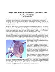
<strong>Chapter</strong> 3<strong>METAL</strong>-<strong>PLATE</strong> <strong>LENS</strong> <strong>ANTENNAS</strong>Paul Wade N1BWT © 1994,1998IntroductionFor portable microwave operation, particularly if backpacking is necessary, dishes or largehorns may be heavy and bulky to carry. A metal-plate lens antenna is an attractivealternative. Placed in front of a modest-sized horn, the lens provides some additional gain,much like eyeglasses on a near-sighted person. The lens antennas I have built and testedare cheap and easy to construct, light in weight, and non-critical to adjust. TheHDL_ANT computer program makes designing them easy as well.There are other forms of microwave lenses — for instance, dielectric lenses and fresnellenses — but the metal-plate lens is probably the easiest to build and lightest to carry, so itis the only type which will be described here.The metal-lens antenna is constructed of a series of thin metal plates with air betweenthem—the curvature of the edges of the plates forms the lens, and the space between theplates forms a series of waveguides. Fortunately, we can get air in a solid form to makeconstruction easier — Styrofoam looks just like air to RF waves, and keeps the metalplates accurately spaced. We use aluminum foil for the plates, attaching it to theStyrofoam with spray adhesive, and shaping the curvature with an X-Acto knife on acompass. Designs are limited to those using circles, to ease construction.BackgroundThese metal-plate lenses were originally described by KB1VC and me at the 1992 EasternVHF/UHF Conference 1 for 10 GHz; there is no good reason to limit them to that band.The need for more gain had become apparent to us during the 1991 10 Ghz contest. Wewere atop Burke Mountain in Vermont, on a day as clear as the tourist brochures. Wecould see Mt. Greylock in Massachutts where KH6CP was located, but it was too far towork with the horn antennas on our Gunnplexers. After K1LPS humped his two-foot dishup the fire tower, we knew that a large dish wasn't the best answer for portable work.Later, we found an article in VHF Communications on lens antennas by Angel Vilaseca,HB9SLV 2 , which intrigued us. It described how to design a metal lens antenna but didnot present expected gain or measured results.We then searched through the references to try to understand how these antennas worked,and finally discovered that the best work was done before we were born, by Kock 3 . Thispaper made it clear how the metal lens antenna worked, and, more importantly, that it didwork!
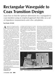
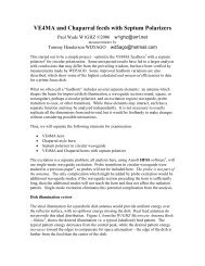
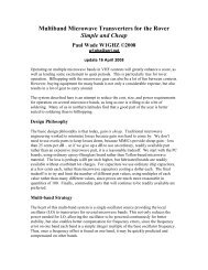
Lens BasicsThe metal plate lens works, in principle, like any other lens. A similar optical lens 4 wouldtake a broad beam of light and shape it, by refraction, into a narrower beam. Refractionoccurs at the interface of two materials in which light travels at different speeds, changingthe direction of travel of the beam of light. If the beam is formed of many rays of light,each one may be bent; the ones at the edge of the beam bend more so they end up parallelto the center rays which are hardly bent at all. For this to work, each ray must takeexactly the same time to travel from its source, at the focal point of the lens, to itsdestination. Since light travels more slowly in glass, a lens is thicker at the middle, to slowdown the rays with a shorter path, and thinner at the edges, to allow the rays with longerpaths to catch up. See Figure 3-1. The curvature of the lens to form the beam exactly isan ellipse; however, for small bending angles, a circle is almost identical to an ellipse, andnearly all optical lenses are ground with sphericalcurves.Since light and RF are both electromagnetic waves, we could use glass or any otherdielectric to make a lens for 10 GHz as well. A recent article 5 described a dielectric lensusing epoxy resin. However, for larger sizes this quickly becomes less attractive, andmost dielectrics are rather lossy at 10 GHz. Low-loss materials are available but arecostly and relatively heavy and difficult to shape.Metal Plate LensSince electromagnetic waves travel at different speeds in waveguide and in free space,why not use waveguides of different lengths to form a lens? This has been done, and isknown as an “eggcrate” lens 6 . However, it is easier to make a group of parallel plateswhich form wide parallel waveguides, and simply shape the input and output edges ofthese waveguides to change path lengths and form the lens surface. This differs from anoptical lens in that the phase of the electromagnetic wave travels faster in a waveguidethan in free space. (We will not attempt to explain this seeming magic here, only referyou to "phase velocity" in any good book on microwaves. Rest assured that no laws ofphysics are being violated.) Thus, the curvature of the metal lens antenna is the oppositeof an equivalent optical or dielectric lens — in this case, concave instead of convex. Wecan still get away with using circular curvatures instead of ellipses as long as we aren'ttrying to bend the rays too sharply. This is why we feed the lens with a small horn, whichdoes part of the beam forming; see Figure 3-2. Of course, if we want both horizontal andvertical beam shaping, we need a spherical shape, so we must shape the surface describedby the edges of the metal plates into a sphere; see Figure 3-3.
CBDFEAHornLensTravel time along AEFD equalstravel time along ABCD.Horn Feeding Lens AntennaFigure 3-1 Figure 3-2EAXISPOINTSOURCEFigure 3-3.Metal Plate Lens Sketch
Lens DesignWhile the HDL_ANT program removes the drudgery from lens design and makes itavailable to amateurs, a general description of lens design might aid in understanding whatis happening and what the computer is telling you.First, some design objectives are needed: how big a lens is desired, and what are thedimensions of the horn feeding it? Gain is determined by aperture area (proportional tothe diameter squared for dishes, horns, and lenses). A good rule of thumb is that doublingthe aperture diameter will increase the gain by 6 dB, since the area of the aperturequadruples. For instance, an 8 inch lens in front of a four inch horn would add 6 dB to thegain of the horn, and a 16 inch lens would add 12 db. So modest gain improvements takemodest sizes, but really big gain requires huge antennas, no matter what kind. However, a6 dB increase in gain will double the range of a system over a line-of-sight path.The horn dimensions may be determined by availability, or you may have the designfreedom to build the horn as well. The beam width of the horn (usually smaller than thephysical flare angle of the horn) is used to determine the focal length of the lens. Kraus 7gives the following approximations for 3 dB beam width in degrees and dB gain over adipole:Eplane =Hplane =56Aeλ67Ahλdegreesdegreesand for gainG ≅ 10log10( 4.5A ⋅ eλ⋅Ahλ ) dB over dipolewhere Aeλ is the aperture dimension in wavelengths in the E-plane and Ahλ is theaperture in wavelengths dimension in the H-plane.These approximations are accurate enough to begin designing. From the beam width anddesired lens aperture, finding the focal length f is a matter of geometry:f = Lens_diameter2tanWEplane( )2The final, and most critical, dimension is the spacing of the metal plates. The blueStyrofoam sheets sold as insulation have excellent thickness uniformity, and 3/4 inch is
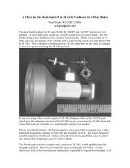
pretty near optimum for 10 GHz, but the actual dimension should be measured carefully.The thickness determines the index of refraction:Index = 1 -⎛⎜⎝λ2spacing ⋅which is the ratio of the wavelength in the lens to the wavelength in free space.⎞⎟⎠Next is calculation of the lens curvature. The optimum curvature is an ellipse, but weknow that spherical lenses have been used for optics since Galileo, so a circle is a usableapproximation. We can show that the circle is an excellent fit if the focal length is morethan twice the lens diameter; photographers will recognize this as an f/2 lens. Thissuggests that the feed horn have a beam width of no more than 28 degrees, or a hornaperture of at least 2 wavelengths.The radius of curvature R of the two lens surfaces is calculated from the lensmaker'sformula 4 :1 ( )1f = n - 1 ⎜R - 1⎝ R⎛1 2⎞⎟⎠where a negative radius is a concave surface. For the single-curved surface in Figure 3-4,one radius is set to infinity. All combinations of R 1 and R 2 which satisfy the formula areequivalent, as shown in Figure 3-5; the computer program calculates the single-curvedlens and the symmetrical double-curved solutions shown in Figure 3-6. The radius ofcurvature as calculated above is for the surface, and thus the central plate, which has thefull curvature. The rest of the plates must be successively wider and have smaller radii sothat the edges of all the plates form a spherical lens surface. This is more geometry, andthe program does the calculations for each plate.The final calculation involves the phase-centers of the horn, so that the lens-to-horndistance matches the focal length. This is a difficult calculation 8 involving calculation ofFresnel sines and cosines 9 ; KB1VC deserves credit for the programming. Without acomputer, you would use trial-and-error looking for best gain. What the calculations willshow is that many horns, particularly the "optimum" designs, have much different phasecenters in the E and H planes. The program offers to make a crude compensation for this,but if possible, the H-plane aperture of the horn should be adjusted slightly to match thephase centers. A few trial runs of the program should enable you to find a goodcombination. If you already have a horn, either try the compensation, or just go with theE-plane phase center.2
HORN PHASE CENTER= = =EEQUIVALENT OPTICAL <strong>LENS</strong>ESRADIUS OF CURVATURE<strong>LENS</strong> FOCAL LENGTH<strong>METAL</strong> <strong>LENS</strong> ANTENNA - SINGLE CURVEFigure 3-4N1BWT & KB1VC= = =EQUIVALENT <strong>METAL</strong> <strong>LENS</strong> <strong>ANTENNAS</strong>All have the same focal lengthFigure 3-5HORN PHASE CENTERHORN PHASE CENTEREERADIUS OF CURVATURERADIUS OF CURVATURE<strong>LENS</strong> FOCAL LENGTH<strong>METAL</strong> <strong>LENS</strong> ANTENNA - DOUBLE CURVEFigure 3-6N1BWT & KB1VC<strong>LENS</strong> FOCAL LENGTHSTEPDISTANCE<strong>METAL</strong> <strong>LENS</strong> ANTENNA - ZONED TO REDUCE THICKNESSFigure 3-7N1BWT & KB1VC
For very large lenses, the size may be reduced by stepping the width of the plates intozones which keep transmission in phase, as shown in Figure 3-7. The program willsuggest a step dimension, if it is useful. At 10 GHz, a step is useful only for lenses largerthan 2 feet in diameter.ConstructionConstruction is straightforward, using metal plates of aluminum foil spaced byStyrofoam), as suggested by HB9SLV 2 . A 2 foot by 8 foot sheet of blue Styrofoam, 3/4inch thickness, is less than five dollars at the local lumberyard, and will make severalantennas. The aluminum foil is attached to the foam using artist's spray adhesive, availableat art supply stores. Spray both surfaces lightly, let them dry for a minute or two, thenspread the foil smoothly on the foam. If the adhesive melts the foam, you are using toomuch.Next mark the outline of a rectangle for each metal plate on the foil — these will be usedlater to cut the foam and line up the plates, so they should all be the same size. Then markthe center of each curve and measure off the radius to the center of the circle. Using acompass with an X-Acto knife attached, place the point at the center of the circle and cutthe curve through the foil into the foam. When all the curves are cut, peel off theunwanted foil, leaving the lens plates. Then cut up the rectangles with a razor blade andstack the blocks into a lens (you did number them!); each rectangle should have foil onone side. If it looks good, glue them up two at a time. The final antenna will be a blockof foam —there is no need to shape the foam to the lens curve. Shrink-wrapping it withthin plastic would be nice weatherproofing. Figure 3-8 is a photo showing a single lensplate on foam and a complete 300 mm. lens for 10 GHz.Some hintsSharp blades really help, and permanent markers don't smear. If the foam is cut halfwaythrough, it will snap cleanly on the line.AdjustmentFirst, a metal-lens antenna only works in the E-plane. This is parallel to the elements of adipole or Yagi antenna, but perpendicular to the wide dimension of a waveguide. Theplates must be perpendicular to the wide dimension to provide gain.The horn should point through the center of the lens, but the focus is not as critical as adish. Aiming is done by pointing the feed horn; the lens focuses the beam more tightlybut does not change beam direction. Tilting the lens will not steer the beam — if youdon't believe this, take an optical lens, like a magnifying glass, focus it on something, andtilt it.
We found that the best gain was with the horn slightly closer to the lens than calculated,probably because of edge effects. Making the size of the plates slightly larger thancalculated would probably eliminate this effect and make the gain a bit higher; since awavelength at 10 GHz is about an inch, an inch or two oversize is plenty.One other interesting effect was found with Gunnplexers: since the transmitter is also thereceive local oscillator, reflected power from the lens adds to the LO power, or subtractswhen out-of-phase. This makes the received signal strength vary every half-inch as thelens-to-horn distance is moved, with very little change at the other station. So adjust thespacing for best received signal. Of course, this effect does not exist on a system with lowLO radiation.Computer ProgramThe lens section of the HDL_ANT calculates the dimensions for the plates of a lens.Since all curves are circles that are easily drawn with a compass, templates are notgenerated. The basic input data is entered interactively, then results presented in tabularform. If you like the results, they may be saved to a file for printing or further processing;if not, try another run with new data.All dimensions are in millimeters. There are two reasons for this: the first is that oddfractions lead to errors in measurement, and the second is that one millimeter is a goodtolerance for 10 GHz lens dimensions. If all measurements are made to the nearest wholemillimeter, good results can be expected. The only exception is the plate spacing, and thatis accurately controlled by the foam thickness.ResultsWe have constructed and tested three metal-plate lens antennas to date: a 150 mm. singlecurvedversion, and 150 mm. and 300 mm. double-curved versions. Figure 3-9 shows the300mm. lens fed by a Gunnplexer WBFM system. All the lenses were designed to be fedwith the standard Gunnplexer horn, which has well matched phase centers, whether bydesign or by accident. Gain measurements on an antenna range, as described in <strong>Chapter</strong>9, are shown in Table 3-1. The lenses perform with about 50% efficiency if we considerthem as having a round aperture; the corners do not contribute significantly, but we madethem square for convenient fabrication and mounting.Antenna Focal distance Gain EfficiencyGunnplexer horn 17.5 dBi 57%horn + 150mm lens ~8 inches 20.9 dBi 45%horn + 300mm lens ~21 inches 27.4 dBi 50%Table 3-1
We also used the lenses during several contests during 1992 through 1997. The 300 mm.lens increased the range of our NBFM Gunnplexer transceivers by approximately 50%, toover 200 km., enabling contacts over new paths. The equipment was still highly portabledue to the light weight of the lens.Further UsesThe metal-lens antenna could be useful at other frequencies: for 5.76 GHz, a foamthickness of around 35 mm. would be good, and at 24 GHz, approximately 8 mm. thickfoam might work, though it might be lossy at that frequency.A lens could also be part of a more complex antenna system. For instance, a divergentlens could be used to provide better illumination for some of the very deep dishes that aresometimes available surplus. A book on optics 4 will show how to change the focal pointsappropriately.Lens SummaryWe have demonstrated that metal-lens antennas may be easily designed and constructedusing the HDL_ANT computer program, and that a book-sized lens, light and ruggedenough for backpacking, provides adequate gain enhancement to double the range of aGunnplexer system.References1. P. Wade, N1BWT, and M. Reilly, KB1VC, "Metal Lens Antennas for 10 GHz,"Proceedings of the 18th Eastern VHF/UHF Conference, ARRL, May 1992, pp. 71-78.2. Angel Vilaseca, HB9SLV, "Microwave Lens Antennas,"VHF Communications, 3/90,pp. 179-189.3. Winston E. Kock, "Metal-Lens Antennas," Proc. I.R.E., Nov. 1946, p. 828-836.4. Eugene Hecht, Optics, Addison-Wesley, 1987.5. John M. Franke, WA4WDL, "Pour an Antenna for X-band," 73, Feb. 1991.6. Carlyle J. Sletten (W1YLV), Reflector and Lens Antennas, Aertech House, 1988.7. John Kraus (W8JK), Antennas, McGraw Hill, 1956.8. Eugen I. Muehldorf, "The Phase Center of Horn Antennas," reprinted in A. W. Love,Electromagnetic Horn Antennas, IEEE Press, 1976.
9. Milton Abramowitz and Irene A. Stegun, Handbook of Mathematical Functions,Dover, 1972.