

WARNING - Atwood Mobile Products
WARNING - Atwood Mobile Products
WARNING - Atwood Mobile Products

Create successful ePaper yourself
Turn your PDF publications into a flip-book with our unique Google optimized e-Paper software.
ENGLISH, FRANCAIS (et Canada) •Installation<br />
THIS INSTRUCTION MANUAL IS FOR USE BY AN AUTHORIZED SERVICE<br />
TECHNICIAN TO INSTALL AN ATWOOD - hydro flameTM FURNACE.<br />
INSTALLER: LEAVE THIS MANUAL WITH THE APPLIANCE.<br />
CONSUMER: RETAIN THIS MANUAL FOR FUTURE REFERENCE.<br />
This furnace design has been certified by the American Gas<br />
Association and Canadian Gas Association for installation in<br />
recreation vehicles as a MSP Category III furnace. Follow this<br />
installation instruction to insure safe operation of the furnace.<br />
Failure to install furnace according to this installation instruction<br />
nullifies the furnace warranty.<br />
SAFETY ALERT SYMBOLS<br />
Safety Symbols alerting you to potential personal safety hazards.<br />
Obey all safety messages following these symbols.<br />
� <strong>WARNING</strong> � CAUTION<br />
avoid possible avoid possible<br />
injury or death injury and/or property damage<br />
<strong>WARNING</strong>: If the information in this manual is<br />
not followed exactly, a fire or explosion may result<br />
causing property damage, personal injury or loss<br />
of life.<br />
— Do not store or use gasoline or other flammable<br />
vapors and liquids in the vicinity of this or any<br />
other appliance.<br />
— WHAT TO DO IF YOU SMELL GAS<br />
• Evacuate all persons from vehicle.<br />
• Shut off gas supply at gas container or source.<br />
• Do not touch any electrical switch, or use any<br />
phone or radio in vehicle.<br />
• Do not start vehicle’s engine or electric generator.<br />
• Contact nearest gas supplier or qualified Service<br />
Technician for repairs.<br />
• If you cannot reach a gas supplier or qualified<br />
Service Technician, contact the nearest fire<br />
department.<br />
• Do not turn on gas supply until gas leak(s) has<br />
been repaired.<br />
— Installation and service must be performed by a<br />
qualified Service Technician, Service Center or<br />
gas supplier.<br />
9<br />
1<br />
MPD 32072<br />
hydro flame TM<br />
7900-II / 8000-II<br />
Series Furnace<br />
Technical Installation Manual<br />
Effective 1/08<br />
INDEX<br />
FURNACE SPECIFICATIONS ..............................................................1<br />
DIMENSIONS ..................................................................1<br />
WEIGHT ........................................................................1<br />
DUCTING CONFIGURATION................................................................1<br />
MINIMUM CLEARANCE TO FLOORBOARDS, WALLS,<br />
& SIMILAR COMBUSTIBLE BUILDING MATERIALS..................................2<br />
SAFETY INFORMATION ................................................................1-2<br />
FURNACE INSTALLATION ..............................................................2-4<br />
CUTOUTS ..................................................................................2<br />
DUCTING................................................................................2-3<br />
Flexible Ducting......................................................................2<br />
Venting Chart ........................................................................3<br />
OPTIONAL INSTALLATION - DIRECTIONAL AIR BOX....................................3<br />
PROPANE GAS CONNECTION ............................................................3<br />
ELECTRICAL CONNECTIONS..............................................................3<br />
Thermostat Installation ............................................................3<br />
Door Installation ....................................................................3<br />
SYSTEM CHECK TESTS ....................................................................4<br />
PROPANE GAS PRESSURE ..............................................................4<br />
FIGURES 1-8 (INCLUDING DC WIRING DIAGRAM) ..........................................4<br />
REPLACEMENT PARTS LIST & DRAWING ..............................................8<br />
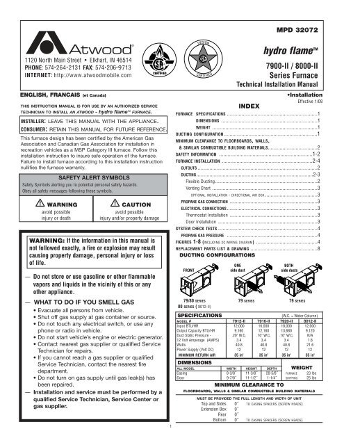
DUCTING CONFIGURATIONS<br />
FRONT<br />
ONE<br />
side duct<br />
BOTH<br />
side ducts<br />
79/80 SERIES 79 SERIES 79 SERIES<br />
80 SERIES ( 8012-II)<br />
SPECIFICATIONS (W.C. = Water Column)<br />
MODEL # 7912-II 7916-II 7920-II 8012-II<br />
Input BTU/HR 12,000 16,000 18,000 12,000<br />
Output Capacity BTU/HR 9,160 12,160 13,680 9,120<br />
Duct Static Pressure - .20" W.C. .10" W.C. .10" W.C. N/A<br />
12 Volt Amperage (AMPS) 3.4 3.4 3.4 1.8<br />
Watts 40.8 40.8 40.8 21.6<br />
Power Supply (Volt DC) 12 12 12 12<br />
MINIMUM RETURN AIR 35 in2 35 in2 35 in2 35 in2 DIMENSIONS<br />
ALL MODEL WIDTH HEIGHT DEPTH WEIGHT<br />
Casing 8-3/8˝ 11-3/8˝ 20-5/8˝ FURNACE 23 lbs<br />
Door 9-7/8˝ 11-1/2˝ 1-1/4˝ SHIPPING 25 lbs<br />
MINIMUM CLEARANCE TO<br />
FLOORBOARDS, WALLS & SIMILAR COMBUSTIBLE BUILDING MATERIALS<br />
MUST BE PROVIDED THE FULL LENGTH AND WIDTH OF UNIT<br />
Top and Sides 0˝ TO CASING SPACERS (SCREW HEADS)<br />
Extension Box 0˝<br />
Rear 0˝<br />
Bottom 0˝ TO CASING SPACERS (SCREW HEADS)
Spacing of 1/4˝ to ducting within 3 feet of furnace must be provided<br />
unless UL listed wire bound vinyl ducts are used. All ducting material<br />
should be rated for continuous use of 200˚F.<br />
NOTE: If zero clearance is maintained from furnace to cabinet structure, a<br />
4˝ x 4˝ air intake cutout must be provided to blower wheel side of furnace<br />
at air intake opening.<br />
NOTE: Clearances are specifically for plywood or similar building<br />
materials surrounding the furnace (i.e. furnace should NOT be located<br />
under furniture or in a closet space where clothing or other material<br />
could be located.)<br />
NOTE: Furnace efficiency rating is a thermal rating determined under<br />
continuous operating conditions, independent of any installation. Eff.<br />
rate is given at 77% minimum, actual efficiency rating may be higher.<br />
*When furnaces are installed to minimum clearances, an additional 16 in 2<br />
of return air must be provided to blower side of furnace, or a 2˝ clearance<br />
the full length and height on blower side must be maintained.<br />
� <strong>WARNING</strong><br />
CARBON MONOXIDE POISONING<br />
• Furnace must be installed and vented to these instructions.<br />
• Improper installation, adjustment, alteration, service or maintenance<br />
can cause injury or property damage.<br />
• Improper installation location may cause furnace to produce negative<br />
pressure, affecting combustion air or venting of other appliances.<br />
� CRITICAL INSTALLATION <strong>WARNING</strong>S<br />
• DO NOT install furnace on material that restricts return air, like carpet<br />
or any soft material such as vinyl.<br />
• DO NOT install where clearance to combustibles cannot be maintained.<br />
• DO NOT modify furnace in any way.<br />
• DO NOT alter furnace for a positive grounding system.<br />
• DO NOT HI-POT furnace unless electronic ignition system (circuit<br />
board) has been disconnected.<br />
• DO NOT use battery charger to supply power to DC model furnace<br />
even when testing.<br />
• DO NOT use 120 volt AC current with DC models.<br />
• DO NOT use furnace cabinet area as a storage compartment.<br />
• DO NOT vent furnace with venting system serving another appliance.<br />
• DO NOT vent furnace to an outside enclosed porch area.<br />
• DO NOT use for temporary heating of buildings or structures under construction.<br />
• Protect building materials from degrading from flue gas exhaust.<br />
• Protect furnace electrical components from water.<br />
USA AND CANADA - FOLLOW ALL APPLICABLE STATE AND LOCAL CODES -<br />
IN THE ABSENCE OF LOCAL CODES OR REGULATIONS, REFER TO CURRENT STANDARDS OF:<br />
• Recreation Vehicles ANSI 1192/NFPA 1192.<br />
• National Fuel Gas Code ANSI Z223.1 /CAN/CGA B149 Installation Codes<br />
• Federal <strong>Mobile</strong> Home Construction & Safety Standard, Title 24 CFR, part<br />
3280, or when this Standard is not applicable, the Standard for Manufactured<br />
Home Installations (Manufactured Home Sites, Communities and Set-Ups),<br />
ANSI A255.1 and/or CAN/CSA-Z240 MH Series, <strong>Mobile</strong> Homes.<br />
• Ground - National Electrical Code ANSI/NFPA No. 70 and/or CSA C22.1<br />
• Park Trailers ANSI 119.5<br />
NOTE: The direct high voltage spark ignition generates a radio frequency<br />
that could cause interference with other microprocessor based equipment.<br />
Locate equipment at least five feet from furnace location. If this distance cannot<br />
be maintained, purchase KIT MPD 37773 (a shielded high voltage lead).<br />
� <strong>WARNING</strong><br />
CARBON MONOXIDE POISONING<br />
• Properly seal vent cap to side wall to prevent carbon monoxide from<br />
entering coach.<br />
• DO NOT draw combustion air from living area. DO NOT vent exhaust air<br />
into the living area or an enclosed porch.<br />
2<br />
Return air is supplied through openings in furnace grille. The return air passage<br />
must be kept clear for furnace to function properly. Refer to MINIMUM CLEARANCE<br />
TO FLOORBOARDS, WALLS & SIMILAR COMBUSTIBLE BUILDING MATERIAL.<br />
STANDARD FURNACE INSTALLATION<br />
General Installation - LOCATION<br />
• Install extension box and vent cap through an exterior wall.<br />
• DO NOT install furnace near tilt-out rooms, slide-outs, doors or other<br />
projections that could obstruct furnace exhaust.<br />
• Locate furnace near midpoint of coach for single furnace applications.<br />
• DO NOT install vent in areas where projections or door openings come<br />
within 6˝ of vent tube opening.<br />
• DO NOT install furnace in an area where wires, pipes, or other objects<br />
will interfere with installation or operation of furnace.<br />
• It is not recommended to install furnace on material that restricts<br />
return air, such as directly on carpet, or soft material (like vinyl).<br />
• If you must install furnace on carpet or soft material, install furnace on<br />
cleats, or on a wood or metal panel extending the full width and depth<br />
of furnace plus minimum clearances to combustibles.<br />
Installation Procedure<br />
ZERO CLEARANCE - AIR INTAKE CUTOUT (FIG 1)<br />
AIR INTAKE OPENING SIDE OF THE BLOWER WHEEL<br />
CUT OUT DIMENSION A B C D<br />
CABINET WALL 2-3/4˝ 3-5/8˝ 4˝ 4˝<br />
A 4˝ x 4˝ cabinet cut out must be provided when there is zero clearance<br />
between furnace and cabinet structure.<br />
1. Set aside combustion air box and exhaust tube extensions for installation<br />
from outside coach.<br />
FURNACE / VENT - CUTOUTS (FIG. 2)<br />
CUT OUT DIMENSION A B<br />
INTERIOR CABINET WALL 8-3/8˝ 11-1/4˝<br />
DO NOT OVERSIZE HOLE - OVERSIZING CAN RESULT IN WATER LEAKAGE<br />
CUT OUT DIMENSION C D E<br />
COACH EXTERIOR WALL FOR VENT 4-7/8˝ 2-1/2˝ 1-3/4˝<br />
DUCTING (FIG. 3)<br />
Proper duct installation is critical to operation of furnace. When<br />
installing ducts, use materials rated for continuous use at 200˚F. Front<br />
discharge temperature should not exceed 250˚F.<br />
Flexible Ducting System<br />
When designing Flexible Duct Systems:<br />
• avoid sharp bends or crushed ducts<br />
• stretch all ducts and run them directly to outlets, keeping quantity<br />
and angles of bends to a minimum<br />
2. A variety of vent kits are available to provide the correct venting from furnace<br />
to outside of vehicle. To determine VENT LENGTH (V DIM), measure the<br />
distance from the back of furnace casing to outside vehicle side wall. For<br />
proper vent kit check your V DIM on VENTING CHART.<br />
3. Ducting available:<br />
TYPE OF DISCHARGE REMOVE<br />
SIDE ONLY duct covers from both sides<br />
COMBINATION front discharge cover plate<br />
FRONT & SIDE and side duct cover plate<br />
FRONT ONLY front discharge cover plate<br />
See DUCTING CONFIGURATIONS for covers and their locations.<br />
4. Install the furnace through cutout in cabinet area. Secure furnace<br />
with two screws FIG 5-A.<br />
OPTIONAL - Installation: The 79-II furnace may be installed in a<br />
cabinet behind a return air grille FIG 4-I. Door MUST be on furnace.<br />
Return air grille must supply a minimum of 35 in 2 of open area and
e in front of door to furnace. Provide an access opening for service<br />
and/or removal of furnace. The furnace must be side ducted (NO front<br />
discharge). Secure furnace to floor with one screw FIG 4-J.<br />
5. Remove cover plate from furnace FIG 4-D. To install duct adapters for<br />
side discharge models, insert back flange over casing and insert tab<br />
into square notch, then twist adapter 180˚ FIG 4-E.<br />
6. Insert furnace into cabinet opening and secure with two screws<br />
through holes in control box flanges FIG 5-A.<br />
7. For side duct applications, slide 4˝ flexible ducting material over<br />
duct adapters and secure FIG 3.<br />
VENTING<br />
1. To install extension box FIG 4-C, apply mastic or sealant to back of<br />
flanges on box. Slide through outside wall cut out and into furnace<br />
air channel. DO NOT FORCE OR BEND PARTS.<br />
2. Apply mastic or sealant to the top and sides of outer edge of vent<br />
cap. DO NOT PLUG HOLES. Slide assembly over furnace exhaust tube FIG<br />
4-B, push into wall and secure with two screws. Note that bottom<br />
flange is not sealed to allow water drainage.<br />
3. The extension box has no minimum clearance requirement FIG 4-C.<br />
4. The vent outlet shall be installed as to be in the same atmospheric<br />
pressure zone as the combustion air intake. No modification of vent<br />
system is allowed.<br />
� <strong>WARNING</strong><br />
CARBON MONOXIDE POISONING<br />
• Properly seal vent system preventing carbon monoxide from entering<br />
coach.<br />
5. Install return-air system to ensure negative pressure, created by the<br />
circulating blower, does not effect another appliance’s combustion<br />
air supply or act to mix products of combustion with circulating air.<br />
All appliances in the furnace cabinet must be directly vented outside.<br />
DIRECTIONAL AIRBOX INSERT (FIG. 7)<br />
1. Remove front door of furnace.<br />
2. Follow shutdown procedure instructions affixed to furnace.<br />
3. Remove sheet metal screw holding circuit board plate to air box.<br />
Retain to fasten Air Box Insert to bottom of air box FIG 7-A.<br />
4. Install Air Box Insert into air box (pay attention to the direction you<br />
would like warm air diverted). Make sure two holes in Air Box Insert<br />
line up with existing holes in air box FIG 7-B.<br />
5. Fasten Air Box Insert to top of air box using a 1/4˝ long #6 sheet<br />
metal screw. Fasten bottom of Air Box Insert and circuit board plate<br />
to bottom of air box using the screw removed.<br />
6. Follow lighting instructions to place furnace in operation.<br />
7. Replace front door on furnace.<br />
PROPANE GAS CONNECTION (FIG. 5)<br />
Connect gas line to brass fitting on left side of furnace. Be sure all<br />
male pipe threads, other than flare fittings, are treated with a sealing<br />
compound resistant to the action of propane (LP) gas. DO NOT put sealing<br />
compound on flare fittings.<br />
1. Insert gas line through hole on left side.<br />
2. Connect gas line to brass fitting inside furnace casing immediately<br />
ahead of gas control valve FIG 5-B.<br />
3. A 3/8˝ flared fitting connection is provided at gas control valve inlet for gas<br />
supply connection to furnace. The gas supply line of furnace must be of adequate<br />
size to provide 11˝ W.C. gas pressure. This pressure must be maintained<br />
under maximum flow conditions with all gas appliances operating.<br />
4. A 1/8˝ N.P.T. plug is accessible for test gauge connection on gas<br />
valve assembly FIG 5-H.<br />
5. Use two wrenches to hold brass fitting and flare nut when tightening<br />
gas line to brass fitting. DO NOT twist valve assembly FIG 6.<br />
3<br />
ELECTRICAL CONNECTION<br />
� <strong>WARNING</strong><br />
INJURY OR PROPERTY DAMAGE<br />
• Label all wires before disconnecting for service. Wiring errors can cause improper,<br />
dangerous operation. Verify proper operation after servicing.<br />
• Disconnect electrical power before servicing.<br />
Conductor Sizing Table - MAX. 10% VOLTAGE DROP - (12 VDC)<br />
CURRENT DRAW (AMPS)<br />
3 4 5 6 7 8 9 10 15<br />
GAGE MAX. LENGTH OF SAE CONDUCTOR (IN FEET) FROM SOURCE TO DEVICE<br />
18 61 45 36 30 26 23 20 18 12<br />
16 96 72 58 48 41 36 32 29 19<br />
� CAUTION<br />
PROPERTY DAMAGE<br />
• This connection is for low-voltage battery or direct current only. Do not<br />
connect to 120- or 240- volts AC.<br />
This furnace is designed for negative ground 12 volts DC only. DO NOT attempt to<br />
alter furnace for a positive ground system or connect furnace directly to 120<br />
volts AC. Damage to furnace components will occur and warranty will be voided.<br />
Use a minimum of 22-18 GA wire to minimize voltage drop. The furnace must<br />
be installed so electrical components are protected from water. To make electrical<br />
connections: SEE WIRING DIAGRAM FIG 8<br />
1. Remove screw from junction box on right side of furnace FIG 5-B.<br />
2. Route wiring to right side of furnace.<br />
3. Connect red wire FIG 5-C to positive side of power supply.<br />
4. Connect black wire FIG 5-D to grounded side of power supply.<br />
5. Connect white wire from furnace to thermostat FIG 5-E.<br />
6. Connect thermostat wire from thermostat to +12VDC of power supply FIG 5-F.<br />
7. Reinstall junction box cover FIG 4-F.<br />
For best performance of furnace when power supply is from a converter equipped<br />
with a charging port, wire the converter to furnace parallel with battery. This provides<br />
consistent voltage to furnace, increasing component life, filtering power<br />
surges and AC spikes FIG 4-G & H.<br />
NOTE: All units are supplied with a power switch which when turned off for<br />
servicing will remove power through the furnace wiring. Switch must be in ON<br />
position for the furnace to operate FIG 5-I.<br />
THERMOSTAT INSTALLATION<br />
The thermostat is very sensitive. HANDLE WITH CARE AT ALL TIMES. Locate thermostat<br />
48˝ to 54˝ above floor on an INTERIOR wall away from areas of abnormal heat or<br />
cold. EXTERIOR wall location must have a 3/4˝ spacer between thermostat and<br />
exterior wall.<br />
Follow manufacturer’s installation instruction provided with thermostat. When<br />
thermostat is not supplied, use a thermostat rated for 12 VDC or 24 VAC min. 1 AMP.<br />
DOOR INSTALLATION<br />
Install door by sliding door flange over control box top flange and fastening door at<br />
bottom with 1/4 turn fastener. Note: To assure sufficient return air to circulating<br />
blower maintain specified clearances.<br />
SYSTEM CHECKS<br />
� <strong>WARNING</strong><br />
FIRE OR EXPLOSION<br />
• Never check for leaks with an open flame.<br />
PROPANE GAS PRESSURE TEST<br />
The furnace and any individual shut-off valve must be disconnected from gas supply<br />
piping system during any pressure testing of system at test pressures of more<br />
than 1/2 PSI.<br />
Before furnace is connected piping systems must be tested to be leak free. The<br />
test must maintain air pressure of at least 6˝ of mercury or 3 PSI for at least 10<br />
minutes.<br />
The entire piping system must be maintained within a range of 10-14˝ W.C. with<br />
all appliances in operation. Test gas connections for leakage with a leak test solution.
V<br />
VENTING CHART<br />
D<br />
KEEP CLEAR<br />
FURNACE VENT<br />
KEEP CLEAR<br />
COACH INTERIOR<br />
A B C<br />
J<br />
A<br />
FM<br />
VENT CABINET DEPTH VENT KIT NO. EXTENSIONS<br />
V DIM. F DIM. M DIM. EXHAUST TUBE EXT.<br />
MIN MAX MIN MAX SS* ALX SS* AL ▼<br />
BOX<br />
0˝ 3-5/8˝ 20-1/2˝ 24˝ 36441 35955 35921 36444 35941<br />
0 MM 92 MM 521 MM 610 MM<br />
3-5/8˝ 7-1/8˝ 24˝ 27-5/8˝ 36442 35956 35928 36446 35947<br />
92 MM 181 MM 610 MM 702 MM<br />
7-1/8˝ 10-5/8˝ 27-5/8˝ 31-1/8˝ 36443 35957 35930 36448 35951<br />
181 MM 270 MM 702 MM 791 MM<br />
1 2<br />
I<br />
F<br />
4<br />
-12 VDC Black<br />
B<br />
C<br />
D<br />
E<br />
+12 VDC Red<br />
DIAGNOSTIC CHART<br />
E<br />
C<br />
A<br />
+12 VDC<br />
H<br />
D<br />
B<br />
G<br />
-12 VDC<br />
FAULT LED INDICATION<br />
Internal Circuit Board Failure Steady on, no flashing<br />
Limit switch/Airflow problems 1 flash with 3-second pause<br />
Flame Sense Fault 2 flashes with 3-second pause<br />
Ignition Lockout Fault 3 flashes with 3-second pause<br />
8<br />
ELECTRODE<br />
4<br />
Black<br />
VALVE<br />
5179 Yellow<br />
Red<br />
Red<br />
3<br />
GROUND<br />
Black<br />
White<br />
LIMIT<br />
6<br />
White<br />
SAIL<br />
SWITCH<br />
White<br />
High Tension<br />
Black<br />
Red<br />
Pwr Blw<br />
DSI<br />
CONTROL<br />
A<br />
B<br />
MOTOR<br />
Red<br />
White<br />
CIRCUIT BREAKER<br />
On/Off Switch<br />
Red +12V DC<br />
Black NEG<br />
White<br />
THERMOSTAT<br />
Blue<br />
H<br />
B<br />
7<br />
5<br />
A<br />
NOTE: The ON/OFF switch,<br />
located in line with the gas<br />
valve, is not used when a<br />
combination circuit breaker<br />
and ON/OFF switch is used.<br />
IMPORTANT Wiring must<br />
be replaced with wire rated<br />
105˚C or higher.<br />
I<br />
B<br />
G<br />
A<br />
G<br />
D<br />
(-) Ground Black (-)<br />
C<br />
E<br />
(+) 12 VDC (+)
hydro flame TM<br />
7900-II / 8000-II Series Furnace<br />
Appareil de chauffage à air chaud<br />
Série 7900-II / 8000-II<br />
1<br />
26<br />
2<br />
3<br />
27<br />
22<br />
Item # Description of Parts<br />
31<br />
1 Front Door<br />
2 Electronic Ignition Board<br />
3 Valve<br />
4 Front Discharge Cover Plate<br />
5 Electrode Cover Plate<br />
6 Electrode<br />
7 Electrode Gasket<br />
8 Heat Exchanger<br />
9 Burner Plate Gasket<br />
10 Sail Switch (79-II)<br />
10 Sail Switch (80-II)<br />
11 Blower Wheel (79-II)<br />
11 Blower Wheel (80-II)<br />
12 Motor (79-II)<br />
12 Motor (80-II)<br />
13 Combustion Wheel<br />
14 Duct Adapter<br />
15 Duct Cover Plate<br />
16 Air Hose<br />
17 Thermostat -SPECIFY COLOR<br />
18 Limit Switch (L-170)<br />
19 Relay<br />
20 On/Off Circuit Breaker<br />
21 Burner Head<br />
22 Manifold<br />
23 Motor Gasket<br />
4<br />
5<br />
6<br />
9 21<br />
25<br />
19<br />
20<br />
18<br />
7<br />
8<br />
Item # Description of Parts<br />
24 Motor Spacer<br />
25 Small Burner Air Baffle - SPECIFY RATE<br />
25 Large Burner Air Baffle - SPECIFY RATE<br />
26 Electronic Ignition Mounting Plate<br />
27 Valve Bracket<br />
28 Vent Kit Specify Length<br />
29 Exhaust Tube Assembly - SPECIFY LENGTH &<br />
MATERIAL<br />
30 Air Box Assembly - SPECIFY LENGTH<br />
31 Orifice - SPECIFY RATE<br />
Élément n˚ Description des pièces<br />
1 Panneau avant<br />
2 Plaquette d'allumage électronique<br />
3 Soupape<br />
4 Couvercle de l'ouverture d'évacuation avant<br />
5 Couvercle de l'électrode<br />
6 Électrode<br />
7 Joint d'étanchéité de l'électrode<br />
8 Échangeur thermique<br />
9 Joint d'étanchéité de la plaque du brûleur<br />
10 Interrupteur à abattant (79-II)<br />
10 Interrupteur à abattant (80-II)<br />
11 Ventilateur (79-II)<br />
11 Ventilateur (80-II)<br />
12 Moteur (79-II)<br />
8<br />
30<br />
17<br />
16<br />
15<br />
30<br />
14<br />
29<br />
11<br />
10<br />
12<br />
24<br />
Élément n˚ Description des pièces<br />
28<br />
23<br />
12 Moteur (80-II)<br />
13 Ventilateur d'air de combustion<br />
14 Adaptateur de conduit<br />
15 Couvercle d'ouverture de branchement<br />
16 Tuyau à air<br />
17 Thermostat -PRÉCISEZ LA COULEUR<br />
18 Rupteur thermique (L-170)<br />
19 Relais<br />
20 Coupe-circuit marche/arrêt<br />
21 Tête de brûleur (79II/80II)<br />
22 Collecteur<br />
23 Joint d'étanchéité du moteur<br />
24 Entretoise du moteur<br />
25 Petit déflecteur d'air du brûleur - PRÉCISEZ<br />
LES CARACTÉRISTIQUES NOMINALES<br />
25 Grand déflecteur d'air du brûleur - PRÉCISEZ<br />
LES CARACTÉRISTIQUES NOMINALES<br />
26 Plaque de montage de l'allumage électronique<br />
27 Support de soupape<br />
28 Module d'évacuation - PRÉCISEZ LA LONGUEUR<br />
29 Exhaust Tube Assembly - PRÉCISEZ LA<br />
LONGUEUR ET LE MATÉRIAU<br />
30 Boîte à air - PRÉCISEZ LA LONGUEUR<br />
31 Lumière - PRÉCISEZ LE CALIBRE<br />
13


