Mini Split Training Manual 2010 - Panasonic
Mini Split Training Manual 2010 - Panasonic
Mini Split Training Manual 2010 - Panasonic

Create successful ePaper yourself
Turn your PDF publications into a flip-book with our unique Google optimized e-Paper software.
Air Conditioning & Heat<br />
Pump Products<br />
Technical <strong>Training</strong><br />
Single <strong>Mini</strong> <strong>Split</strong> 9,000-24,000 Btu<br />
Flexi-Multi 19,000-31,000 Btu<br />
Single <strong>Mini</strong> <strong>Split</strong> 26,000-42,000 Btu
Table of contents Page<br />
1) Dealer training & certification………………………………………………….2-3<br />
2) Sanyo technical contact information…………………………………………....4<br />
3) Product Line-up model & serial number identification…………………….…5-9<br />
4) (RAC) Product line-up, 9,000-24,000 Btu, single minis & flexi multi ……….10-13<br />
5) Installation clearances…………………………………………………………..14-16<br />
6) Condensate pumps………………………………………………………………17-22<br />
7) Tubing size, length, elevation, insulation and refrigerant charge……………23-24<br />
8) Wiring 9,000-24,000 Btu & flexi multi……………………………………..….25-32<br />
9) Wireless, wired remote controls, address setting & basic functions………...33-39<br />
10) Troubleshooting 9,000-24,000 Btu & flexi multi…………………………....40-60<br />
11) Step-by-step troubleshooting procedure 9,000-24,000 Btu & flexi multi….60-63<br />
12) (PAC) Product line-up 26,000-42,000 Btu systems ………………………....64-70<br />
13) Operation range 26,000-24,000 Btu, tubing, length, refrigerant charge…..71-72<br />
14) Wiring 26,000-42,000 Btu…………………………………………………….73-74<br />
15) Remote control line-up……………………………………………………….75-76<br />
16) Troubleshooting with the RCS-TM80BG remote controller………………77-80<br />
17) Wireless remote controller…………………………………………………...81<br />
18) Troubleshooting 26,000-42,000 Btu…………………………………………82-88<br />
19) Error code details 26,000-42,000 Btu………………………………………..89-101<br />
20) EPROM chip and replacing an indoor or outdoor circuit board………....102-106<br />
21) Performance data 9,000-24,000 Btu pressure / temperature charts………107-120<br />
1
WWW.US.SANYO/HVAC.COM<br />
Sanyo offers a wide variety of<br />
Technical Service <strong>Training</strong><br />
Hands-On Service <strong>Training</strong> (Kennesaw Facility):<br />
Come to our Georgia facility and train on live ECO-i & <strong>Mini</strong>-<strong>Split</strong><br />
equipment<br />
On-Demand Videos train at your leisure:<br />
� ECO-i installation & commissioning<br />
� Troubleshooting the 3 way solenoid<br />
� ECO-i maintenance controller<br />
� ECO-i service (3 parts)<br />
� <strong>Mini</strong> split installation & service<br />
� How to display room temperature on a wired remote controller<br />
� Dismantling the “K” wall mounted unit.<br />
� PAC installation & service<br />
� Installing a STK-RCS-7TWSUA wired remote controller<br />
Webinar Classes:<br />
� How to use the RCS-TM80BG as a service tool.<br />
� <strong>Mini</strong> <strong>Split</strong> & Flexi Multi Installation<br />
� ECO-i Installation<br />
� ECO-i Commissioning<br />
� EC0-i Service<br />
Online Dealer Certification Courses:<br />
� ECO-i installation, Commissioning & Service<br />
� <strong>Mini</strong> <strong>Split</strong> & Flexi Multi Installation & Service<br />
You will be required to take and pass an on-line test after the<br />
class to become a Sanyo Dealer<br />
2
WWW.US.SANYO/HVAC.COM<br />
SANYO Dealer Network: Certification on Demand<br />
On our website main page click on the training tab then the<br />
Online Dealer Certification Courses tab<br />
SANYO now offers comprehensive training classes all on-line, that can be taken at your<br />
own pace. By successfully completing the 3 consecutive courses, you can become a<br />
certified gold, silver or bronze SANYO HVAC dealer.<br />
ECO-i Installation Course:<br />
This training course focuses on Sanyo’s ECO-i Multi <strong>Split</strong> Variable Flow Refrigerant<br />
(VRF) system. Upon completion of this course participants should have attained the<br />
required skills to properly configure and install the ECO-i system.<br />
ECO-i Commissioning:<br />
This training course focuses on Sanyo’s ECO-i Multi <strong>Split</strong> Variable Flow Refrigerant<br />
(VRF) system. Upon completion of this course participants should have attained the<br />
required skills to properly configure and commission the ECO-i system.<br />
ECO-i Service:<br />
This training course focuses on Sanyo’s ECO-i Multi <strong>Split</strong> Variable Flow Refrigerant<br />
(VRF) system. Upon completion of this course participants should have attained the<br />
required skills to properly configure a system, install the system, commission the system<br />
and to conduct in depth service, troubleshooting and diagnostics.<br />
<strong>Mini</strong> <strong>Split</strong> and Flexi Multi Installation & Service:<br />
This training course provides the participants with an overview of Sanyo’s R-410a oneto-one<br />
split and Flexi Multi products including installation requirements, unit<br />
specifications, operating characteristics and a detailed review of service and<br />
troubleshooting procedures.<br />
<strong>Mini</strong> Spilt Models 26-4272R:<br />
This training course provides the participants with an overview of Sanyo’s R-410a oneto-one<br />
Pac (26K - 42K BTU) products including installation requirements,<br />
commissioning procedures, operating characteristics and a detailed review of service and<br />
troubleshooting procedures.<br />
3
SANYO HVAC CONTACT INFO<br />
TECHNICAL SUPPORT:<br />
HVAC.SERVICE@SNA.SANYO.COM<br />
WEBSITE:<br />
WWW.US.SANYO/HVAC.COM<br />
NOTE: Service, installation, user guides<br />
and submittals can be obtained through<br />
our website.<br />
4
Product Overview:<br />
� Sanyo’s product line offers environmentally friendly 0 ozone depletion<br />
potential, R410a refrigerant.<br />
� All models meet and exceed Federal DOE guidelines for energy<br />
efficiency, 13+S.E.E.R<br />
Caution for Installation:<br />
� Higher Pressure ( R410a is 1.6 times higher than R22.)<br />
� Compressor oil is different.<br />
� R410a uses Polyvinyl Ether Oil (Synthetic fluid)<br />
� Different gauge-manifold, charge hose, etc., must be used for R410a.<br />
� Near-Azeotrope Type Refrigerant<br />
� Only charge the refrigerant in liquid form.<br />
� New refrigerant piping is required for all R410a installs.<br />
5/16” Service Ports:<br />
Service ports are different then on R22 systems. Sanyo R410a systems have<br />
5/16” male flare fittings. Adaptor must be used when using 1/4” hoses.<br />
These adaptors (5/16” ffl x 1/4” mfl) are available from the following<br />
manufacturers:<br />
� Ritchie Part Number 19173<br />
� Ritchie Part Number 93825(Ball Valve)<br />
� JB Industries Part Number QC-S5<br />
5
What is an Inverter Air Conditioner?<br />
� Unlike a standard air conditioner which uses a constant fixed speed<br />
compressor, the DC inverter controlled compressor will always start at<br />
it’s minimum revolutions and slowly speed up to meet current system<br />
demand. This greatly reduces the power surge needed at start up.<br />
� This is obtained by converting incoming AC power to DC power, thereby<br />
making it possible to accurately control the systems capacity. When the<br />
maximum capacity is not required, the compressor revolution is<br />
decreased.<br />
� This means the power decreases too, which results in increased system<br />
efficiency with reduced operating electrical costs.<br />
� Variable speed inverter driven compressors provide a range of capacities<br />
and are listed with minimal, nominal and maximum capacities<br />
� The compressor starts at a minimum frequency of 23% of maximum<br />
capacity<br />
� Allows for low superheat of 0-5 degrees<br />
� Allows for greater utilization of the evaporator<br />
� The Sanyo Inverter is a true DC compressor<br />
6
Cooling Capacity in BTU/h<br />
Model Number by System:<br />
Indoor Unit Type<br />
K: Wall Mounted<br />
T: Ceiling Suspended<br />
X: 4way Ceiling<br />
Recessed<br />
U: Concealed Duct<br />
M: Multi-Zone<br />
System:<br />
18KHS72<br />
18 K H S 7 2<br />
Voltage: 1-115v<br />
2-208/230<br />
Model Series No.<br />
S: wireless remote Control<br />
W: wired Remote Control<br />
H: Heater<br />
Function<br />
H: Heat Pump<br />
L: Low Ambient<br />
Model Number by Component:<br />
Component:<br />
KHS1872 / CH1872<br />
Indoor Unit Outdoor Unit<br />
Indoor Unit Type<br />
K: Wall Mount<br />
T: Ceiling Suspended<br />
X: 4way Ceiling Recessed<br />
U: Concealed Duct<br />
C: Outdoor Unit<br />
M: Multi-Zone<br />
K H S 1 8 7 2<br />
Voltage<br />
1-115v<br />
2-208/230v<br />
Model Series No.<br />
Cooling Capacity<br />
In BTU/h<br />
S: Wireless remote<br />
W: Wired remote<br />
H: Heater<br />
Function<br />
H: Heat Pump<br />
7
Warranty Policy:<br />
Serial number Identification:<br />
0<br />
0<br />
6 3 3 7 5 1 6 7 3<br />
Quarter of Year:<br />
1: Jan - Mar<br />
2: Apr - Jun<br />
3: Jul - Sep<br />
4: Oct - Dec<br />
Year of Manufacture<br />
Consecutive Sequence<br />
Number<br />
After September 1, 2009:<br />
Standard warranty on Single <strong>Split</strong> and Flexi-Multi Systems is 7<br />
years compressor & 5 years functional parts. The new extended<br />
warranty is in effect for Sanyo ducted and ductless split system<br />
installed on or after Sept 1 2009<br />
Before September 1, 2009:<br />
All R22, ECOI, Single and Flexi-Multi Systems split models<br />
installed before Sept 1 2009 remain 6 years compressor & 1 year<br />
on functional parts.<br />
8
Certifications<br />
http://www.ahridirectory.org<br />
Sanyo Products meet or exceed all major regulating agencies<br />
equipment standards of performance and compliance.<br />
9
RAC Product Lineup: R410a, Single Zone, Inverter (16-20 SEER)<br />
K Series Wall Mounted<br />
X Series Ceiling recessed<br />
Type<br />
Single Cooling<br />
*Cooling to<br />
50 deg f<br />
Single Cooling<br />
*Low ambient<br />
cooling to<br />
0 deg f<br />
Heat Pump<br />
Cooling &<br />
Heating to 0<br />
Deg f<br />
Type<br />
Single Cooling<br />
*Cooling to<br />
50 deg f<br />
Single Cooling<br />
Low ambient<br />
Cooling to<br />
0 Deg f<br />
Heat Pump<br />
Cooling &<br />
Heating to 0<br />
Deg f<br />
Wireless Remote Control (Standard)<br />
Wired Remote Control (Optional)<br />
Wireless Remote<br />
Control<br />
(Standard)<br />
9,000<br />
BTU<br />
16 SEER<br />
09KS71<br />
09KLS71<br />
09KHS71<br />
12,000<br />
BTU<br />
17 SEER<br />
12XS71<br />
12XLS71<br />
12XHS71<br />
12,000<br />
BTU<br />
17 SEER<br />
12KS71<br />
12KLS71<br />
12KHS71<br />
18,000<br />
BTU<br />
20 SEER<br />
18XS71<br />
18XLS71<br />
18XHS71<br />
STK-RCS-7TWSU<br />
Wired Remote Control<br />
(Optional)<br />
18,000<br />
BTU<br />
20 SEER<br />
18KS72<br />
18KLS72<br />
18KHS72<br />
24,000<br />
BTU<br />
17 SEER<br />
24KS72<br />
24KLS72<br />
24KHS72<br />
STK-KCW1<br />
Wiring Harness<br />
10
K Series<br />
Wall Mounted<br />
Flexi Multi Product Lineup:R410a, Multi Zone, Inverter,<br />
(14.8-16.8 SEER)<br />
X Series<br />
Ceiling Recessed<br />
Outdoor Units<br />
<strong>Mini</strong>mum of Two Indoor<br />
Units Required<br />
Type<br />
Cooling<br />
Only<br />
Heat<br />
Pump<br />
Type<br />
Cooling<br />
Only<br />
Heat<br />
Pump<br />
7,000BTU<br />
KMS0772<br />
KMHS0772<br />
9,000BTU<br />
KMS0972<br />
KMHS0972<br />
12,000BTU<br />
KMS1272<br />
KMHS1272<br />
Wireless Remote Control (Standard)<br />
Wired Remote Control (Optional)<br />
Wireless Remote<br />
Control<br />
(Standard)<br />
9,000BTU<br />
XMS0972<br />
XMHS0972<br />
Type<br />
Cooling<br />
Only<br />
Cooling Low<br />
Ambient<br />
Heat<br />
Pump<br />
12,000BTU<br />
XMS1272<br />
XMHS1272<br />
19,000BTU<br />
CM1972<br />
CLM1972<br />
CMH1972<br />
18,000BTU<br />
XMS1872<br />
XMHS1872<br />
24,000BTU<br />
CM2472<br />
CLM2472<br />
CMH2472<br />
STK-RCS-7TWSU<br />
Wired Remote Control<br />
(Optional)<br />
18,000BTU<br />
KMS1872<br />
KMHS1872<br />
24,000BTU<br />
KMS2472<br />
KMHS2472<br />
31,000BTU<br />
CM3172<br />
CLM3172<br />
CMH3172<br />
STK-KCW1<br />
Wiring Harness<br />
11
Negative Ion Generator<br />
While operating, this unit generates negative ions that<br />
freshen up the conditioned space.<br />
Enlarged View of the ION Generator<br />
(Can Be Disabled)<br />
12
Operating Range 9,000-24,000 BTU Single <strong>Mini</strong> <strong>Split</strong>s<br />
Model<br />
� All RAC systems stop operating in temperatures below Cut-Off –Temperature.<br />
� Operation below Operating Range is out of warranty.<br />
� *3 No maximum temperature cut-out.<br />
Operating Range for the Flexi-Multi Series<br />
Model<br />
Operating Range Limits Based On Outdoor Temperature ( Degrees F )<br />
CH0971<br />
CH1271<br />
CH1872<br />
CH2472<br />
C0971<br />
C1271<br />
C1872<br />
C2472<br />
CL0971<br />
CL1271<br />
CL1872<br />
CL2472<br />
Operating Range Limits Based On Outdoor Temperature ( Degrees F )<br />
CMH1972<br />
CMH2472<br />
CMH3172<br />
CM1972<br />
CM2472<br />
CM3172<br />
CLM1972<br />
CLM2472<br />
CLM3172<br />
Design Outdoor Operating Range Cooling Cut-Off Heating Cut-Off<br />
Cooling Heating Min. Max. Min. Max.<br />
Min. Max. Min. Max. Outdoor Outdoor Outdoor<br />
Outdoor<br />
0F DB<br />
50 DB 115F DB 50 DB *3<br />
0F DB<br />
Design Outdoor Operating Range Cooling Cut-Off Heating Cut-Off<br />
C ooling H eating Min. Max. Min. Max.<br />
M in. M ax. M in. M ax. Outdoor Outdoor Outdoor Outdoor<br />
67 DB<br />
*1<br />
-4 D B<br />
0F DB<br />
N/A N/A<br />
0F DB<br />
N/A<br />
75F DB<br />
65F WB<br />
75F DB<br />
65F W B<br />
-4 DB<br />
-4 DB<br />
-4 DB<br />
-8 DB<br />
-13 DB<br />
55F DB<br />
*2<br />
N/A<br />
-8 DB 122F DB<br />
N/A N/A<br />
-8 D B *4<br />
N/A N/A N/A<br />
*1: 32F DB: Combined with KMS1872 and/or KMS2472 / 23F DB: When combined only<br />
with KMS0772, KMS0972 and/or KMS1272.<br />
*2: 28F DB: Combined with KMS1872 and/or KMS2472 19F DB: When combined only<br />
with KMS0772, KMS0972 and/or KMS1272.<br />
*4: No maximum temperature cut-out<br />
13
Basic System Layout<br />
Return Air<br />
Supply Air<br />
� ¾” PVC adaptor provided for the condensate drain<br />
Drain<br />
� Wireless remote control (Standard)<br />
� Wired remote control (Optional)<br />
Narrow Pipe<br />
Wide Pipe<br />
14
Indoor Unit Site Selection<br />
(“K” Series Wall Mounted)<br />
Note<br />
Wall<br />
Note<br />
Ceiling<br />
Bottom of indoor unit<br />
to the finished floor.<br />
(5 foot minimum)<br />
Floor<br />
Note<br />
Installation clearances vary depending on the size and<br />
model of the unit being installed. Always refer to the<br />
installation manual for proper unit clearances.<br />
15
Intake<br />
min. 2”<br />
Site Selection<br />
(Outdoor Unit)<br />
Discharge<br />
min. 16”<br />
Intake<br />
min. 2”<br />
Above<br />
min. 7ft<br />
(<strong>Mini</strong>mum Clearances Shown)<br />
Valve<br />
side<br />
min. 10”<br />
Always leave room for service and cleaning when<br />
selecting the installation site.<br />
16
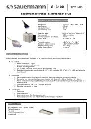
Condensate Pump<br />
(Installation and Wiring)<br />
Example of the Sauermann 3100 Series<br />
The above condensate pump is an after market item. Sanyo does<br />
not manufacture or warranty these items. The installer may<br />
choose the pump of his/her personal choice.<br />
17
Mounting the Receiver<br />
(Float Safety Switch)<br />
First place the self-adhesive support that holds the detection unit<br />
Attach Bleeder<br />
Hose Here<br />
Bleeder Hose<br />
Attach the condensate hose before mounting the self-adhesive support to<br />
insure proper location and attach the supplied air bleeder hose<br />
18
Mounting the Condensate Pump<br />
Keep into account the maximum distance between the pump and the<br />
detection unit (vertical suction-head) refer to installation manual. Clear<br />
tubing available as an optional accessory. (Inner diameter 0.24”)<br />
19
Condensate Wiring for RAC<br />
9,000-24,000 BTU<br />
Sauermann Condensate Pump Wiring Instructions<br />
This diagram is for the following Sanyo Indoor Unit Models:<br />
KMS0772, KMHS0772, KMS0972, KMHS0972, KMS1272, KMHS1272,<br />
KS1872, KHS1872, KMS1872, KMHS1872, KS2472, KHS2472,<br />
KMS2472 & KMHS2472<br />
(Please note all the above Sanyo models operate off of 208/230 VAC 60Hz)<br />
Diagram is shown utilizing a Sauermann SI-3100-2 or SI-1730-2 Condensate Pump<br />
Power Supply<br />
208/230 VAC 60 Hz<br />
Sanyo Indoor Unit’s<br />
Terminal Strip<br />
1 2 G 3<br />
630 mA Fuse<br />
L1 L2 G C NC<br />
Sauermann Pump<br />
Model SI-3100-2 & SI-1730-2<br />
(208/230 VAC 60 Hz)<br />
Power Supply<br />
208/230 VAC 60 Hz<br />
Sanyo Outdoor Unit’s<br />
Terminal Strip<br />
1 2 3 4 5 6 G<br />
Power Supply<br />
Outdoor Unit<br />
208/230 VAC 60 Hz<br />
Pump Wire Colors<br />
for SI-3100-2<br />
Power Wiring:<br />
Brown Wire = L1<br />
Blue Wire = L2<br />
Green Wire = Ground<br />
Alarm Circuit Wires:<br />
Yellow Wire = C<br />
White Wire = N/C<br />
� Land the power wires from the pump to terminals 1 & 2 on<br />
the indoor unit.<br />
� Break line 3 on the indoor unit for the safety switch wiring.<br />
20
Condensate wiring for a PAC product<br />
(26,000-42,000 BTU)<br />
Sauermann Condensate Pump Wiring Instructions<br />
This diagram is for the following Sanyo Indoor Unit Models:<br />
KHS2672R, KHHS2672R, KHS3072R, KHS3672R, THW2672R,<br />
THHW2672R, THW3672R, THHW3672R, THW4272R, XHW2672R,<br />
XHW3672R, XHW4272R, UHW2672R & UHW3672R<br />
(Please note all the above Sanyo models operate off of 208/230 VAC 60Hz)<br />
Diagram is shown utilizing a Sauermann SI-3100-2 or SI-1730-2 Condensate Pump<br />
Power Supply<br />
208/230 VAC 60 Hz<br />
Sanyo Indoor Unit’s<br />
Terminal Strip<br />
1 2 G<br />
Pump Wire Colors<br />
for SI-3100-2<br />
630 mA Fuse<br />
Power Wiring:<br />
Brown Wire = L1<br />
Blue Wire = L2<br />
Green Wire = Ground<br />
Alarm Circuit Wires:<br />
Yellow Wire = C<br />
White Wire = N/C<br />
L1 L2 G C NC<br />
Sauermann Pump<br />
Model SI-3100-2 & SI-1730-2<br />
(208/230 VAC 60 Hz)<br />
Indoor PCB Board<br />
CN09<br />
Red Connector<br />
Float Switch Jumper<br />
(CN09) Red Connector<br />
Located on Indoor<br />
Unit’s PCB<br />
Note: The X & U<br />
style indoor units<br />
have a primary float<br />
switch installed from<br />
the factory. When<br />
adding an additional<br />
aux. pump, wire the<br />
aux. pumps N/C<br />
contacts in series<br />
with the indoor<br />
unit’s factory<br />
installed float switch.<br />
� Cut the CN09 connector and wire the safety through this<br />
connection on the indoor circuit board.<br />
21
The Following Models are Equipped<br />
With Built in Drain Pumps<br />
• XHX models: Four Way Supply Ceiling Recessed<br />
• UHX models: Concealed Duct ( Low Static Models)<br />
• All of the above models have built in float switches<br />
These pumps have a limited vertical lift as shown<br />
Connect Drain Line Here<br />
Pan Inspection Port<br />
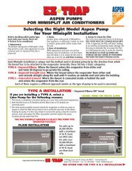
22
RAC 9,000-24,000 Btu<br />
Flexi-Multi 19,000-31,000 Btu<br />
Tubing, Sizes, & Elevation Difference<br />
Refrigerant Charge Adjustment & Insulation Chart<br />
23
Tubing Limitations:<br />
(Flexi-Multi Systems)<br />
Tubing Length = L1 Elevation Difference = H1<br />
(H3)<br />
Model<br />
CMH1972<br />
CMH2472<br />
CMH3172<br />
Indoor 1<br />
(H1) = Elevation Difference<br />
Max.<br />
Allowable<br />
Tubing Length<br />
Per Unit<br />
(ft.)<br />
82<br />
82<br />
(L1)= Tubing length<br />
Max. Allowable Total Tubing<br />
Length at Shipment Unit Pre-<br />
Charged Length (L1+L2+L3) or<br />
(L1+L2+L3+L4) (ft.)<br />
150 (L1+L2+L3)<br />
150 (L1+L2+L3+L4)<br />
100 150 (L1+L2+L3+L4)<br />
Limit of Total Tubing Length<br />
Exceeding Pre-Charged Length<br />
Maximum Piping Length<br />
(L1+L2+L3) or (L1+L2+L3+L4)<br />
(ft.)<br />
150 (L1+L2+L3)<br />
200 (L1+ L2+ L3+L4)<br />
200 (L1+ L2+ L3+L4)<br />
Limit of Elevation<br />
Difference<br />
(H1, H2, H3, H4)<br />
(ft.)<br />
Outdoor Unit Indoor Unit<br />
Above Above<br />
50<br />
50<br />
50<br />
Indoor 2<br />
(L4)<br />
Indoor 3<br />
(L3)<br />
Indoor 4<br />
(L2)<br />
(H2)<br />
50<br />
50<br />
50<br />
Required Amount<br />
of Additional<br />
Refrigerant (Oz. / ft.<br />
N/A<br />
(H4)<br />
0.22 Oz. / ft.<br />
0.22 Oz. / ft.<br />
24
� Note: The 9,000 & 12,000 BTU models in a single split<br />
combination require a 115 volt power supply.<br />
� Installation wiring for 115 volt single split systems.<br />
� Disconnect switch is field supplied.<br />
� Indoor disconnect not required. Follow local codes.<br />
� 14 gauge wire minimum<br />
1<br />
2<br />
3<br />
Hot<br />
Neutral<br />
12-15 VDC Signal<br />
G G<br />
Indoor Unit<br />
RAC Single <strong>Split</strong> System<br />
(A/C & HP)<br />
Typical Installation Wiring For:<br />
C-CL0971, CH0971, C-CL1271 & CH1271<br />
Disconnect<br />
Switch<br />
(Field<br />
Supplied)<br />
Follow Local<br />
Electrical<br />
Codes<br />
1<br />
2<br />
3<br />
4<br />
5<br />
6<br />
G<br />
Outdoor Unit<br />
Disconnect Switch<br />
(Field Supplied)<br />
Hot<br />
Neutral<br />
Ground<br />
115 VAC (Power Supply)<br />
25
� Installation wiring for the 230 volt single split systems.<br />
� These 230 volt systems are polarity sensitive.<br />
� Disconnect switch is field supplied.<br />
� Indoor disconnect not required. Follow local codes.<br />
� 14 gauge wire minimum.<br />
1<br />
2<br />
3<br />
Disconnect Switch<br />
(Field Supplied)<br />
Follow Local Codes<br />
115V<br />
115V<br />
12-15 VDC Signal<br />
G G<br />
Indoor Unit<br />
RAC Single <strong>Split</strong> System<br />
(A/C & HP)<br />
Typical Installation Wiring For:<br />
C-CL1872, CH1872, C-CL2472 & CH2472<br />
1<br />
2<br />
3<br />
4<br />
5<br />
6<br />
G<br />
Outdoor Unit<br />
Disconnect Switch<br />
(Field Supplied)<br />
L1<br />
L2<br />
Ground<br />
208/230 VAC (Single Phase)<br />
Power Supply<br />
26
Flexi-Multi<br />
(Cooling Only & HP)<br />
� Installation wiring for the 230 volt multi split systems.<br />
� These 230 volt systems are polarity sensitive.<br />
� Disconnect switch is field supplied.<br />
� Indoor disconnect not required. Follow local codes.<br />
� 14 gauge wire minimum.<br />
Disconnect<br />
Switch<br />
(Field<br />
Supplied)<br />
Follow Local<br />
Electrical<br />
Typical Installation Wiring For:<br />
CM-CLM-CMH, 1972, 2472, 3172<br />
Indoor Unit<br />
1<br />
2<br />
3<br />
G<br />
1<br />
2<br />
3<br />
G<br />
1<br />
2<br />
3<br />
G<br />
115 V<br />
115 V<br />
12-15 VDC<br />
115 V<br />
115 V<br />
12-15 VDC<br />
115 V<br />
115 V<br />
12-15 VDC<br />
Outdoor Unit<br />
1<br />
2<br />
3<br />
G<br />
4<br />
5<br />
6<br />
G<br />
7<br />
8<br />
9<br />
G<br />
“A”<br />
“B”<br />
“C”<br />
1<br />
2<br />
G<br />
Disconnect Switch<br />
Field Supplied<br />
L1<br />
L2<br />
Ground<br />
208/230 VAC (Single Phase)<br />
Power Supply<br />
27
Typical Mis-Wiring<br />
(RAC systems 9,000-24,000)<br />
Example: The wires landed on terminals 1 & 2 from the<br />
indoor unit to the outdoor unit are crossed.<br />
1. You just completed the installation and powered the system.<br />
2. You turn the indoor unit on with the wireless remote control.<br />
3. The operation light instantly starts blinking.<br />
1<br />
2<br />
3<br />
G<br />
The operation light should always be steady on when the unit is<br />
running. Blinking means there is a fault.<br />
1<br />
2<br />
3<br />
G<br />
28
Typical Mis-Wiring<br />
(RAC systems 9,000-24,000)<br />
Example: The wire landed on terminal 3 is open or shorted.<br />
� Is there a condensate pump installed. If properly installed the safety<br />
switch wiring should be landed on terminal three. Determine if the<br />
pump has failed<br />
� Proper voltage reading at the indoor & outdoor units between<br />
terminals 2 & 3 should be 12-15v DC.<br />
1<br />
2<br />
3<br />
G<br />
X<br />
1<br />
2<br />
3<br />
G<br />
29
Indoor A<br />
Indoor B<br />
Indoor C<br />
Typical Mis-Wiring<br />
(Flexi-multi systems)<br />
1. Keep track of the wiring for each circuit. A to A, B to B, C to C<br />
2. Keep track of the piping. Piping circuit A to wiring circuit A and<br />
so on for all the circuits.<br />
3. This illustration displays the most common wiring / piping mistake<br />
made on the Flexi-Multi systems.<br />
1<br />
2<br />
3<br />
G<br />
1<br />
2<br />
3<br />
G<br />
1<br />
2<br />
3<br />
G<br />
Condensing<br />
Unit<br />
1<br />
2<br />
3<br />
G<br />
4<br />
5<br />
6<br />
G<br />
7<br />
8<br />
9<br />
G<br />
“A”<br />
“B”<br />
“C”<br />
1<br />
2<br />
G<br />
Disconnect Switch<br />
Field Supplied<br />
Ground<br />
L1<br />
L2<br />
30
Flexible Combinations<br />
(Systems designed for each job)<br />
� Maximum Connecting Capacity of 130 %<br />
� <strong>Mini</strong>mum of two indoor units required<br />
7k<br />
19k<br />
9k<br />
12k<br />
24k<br />
18k<br />
New Ceiling mounts available <strong>2010</strong><br />
31k<br />
24k<br />
Ceiling recessed and wall mounts can be mixed and matched<br />
31
Distribution Header<br />
(CM2472, CLM2472 and CMH2472)<br />
D<br />
C<br />
B<br />
A<br />
Any combination<br />
can be used on any<br />
circuits A, B, C, or D<br />
to a maximum of<br />
THREE indoor unit’s<br />
total<br />
� The 24,000 BTU series is designed for THREE<br />
indoor units maximum.<br />
� Any of the four ports can be used in any combination<br />
but only Three circuits Maximum.<br />
� The “1/2 “circuit is for larger BTU indoor units.<br />
� CM, CLM, CMH1972= 3 indoor unit’s maximum<br />
� CM,CLM,CMH2472= 3 indoor unit’s maximum<br />
� CM, CLM, CMH3172= 4 indoor unit’s maximum<br />
32
Wireless Remote Controller<br />
Ion<br />
1 Hour Timer<br />
Temp Temp Setting<br />
Quiet<br />
Fan Speed Speed<br />
Flap Flap<br />
Sensor<br />
12/24 Hour Format<br />
Addres Address s<br />
ACL / Reset<br />
� � The remote control when in the “ON” state transmits a signal every 5 minutes<br />
� � The remote control will restart the unit after a power interruption.<br />
� � It is important to locate the remote in an area where the signal can be received<br />
by the indoor unit.<br />
� � Once a signal is transmitted a “low tone beep” should be heard at the indoor<br />
unit.<br />
� � Once the outdoor unit has been started in heating or cooling there is a 5 minute<br />
minimum run time.<br />
� � There will also be a 3 minute delay on startup of the outdoor unit.<br />
� � Occasionally lighting can affect the signal.<br />
� � Maximum Distance From the Indoor Unit is 26 Feet<br />
Tem Temperature perature Sensor<br />
On / Off<br />
Mode<br />
Ni Night ght Setback<br />
Hig High Power<br />
Timer Setup<br />
33
Occasionally lighting can affect the signal.<br />
Page 4 of the installation manual states:<br />
� Install the indoor unit more than 1 meter (3.3’) away<br />
from electronic devices such as televisions, radios,<br />
telephones, etc.<br />
� Electrical noise from these may affect operation.<br />
� Change the batteries to the remote every 6 months. Press<br />
the ACL button when new batteries are installed<br />
34
Wired Remote Controller<br />
STK-RCS-7TWSU<br />
Wired Remote Control<br />
(Optional)<br />
Temperature Set<br />
Fan Speed<br />
Flaps<br />
Night Setback<br />
All Clear<br />
Reset<br />
On/Off Button<br />
Mode<br />
1 Hour Timer<br />
Sensor<br />
The STK-KCW1 Wiring harness is necessary to convert a “K”<br />
model from wireless to a wired remote control.<br />
The “X” series ceiling recessed models are factory wired and the<br />
wiring harness is not needed.<br />
35
Address Setting of the Remote Control Unit<br />
The address can be set in order to prevent interference between remote<br />
controllers when two indoor units are installed near each other. Turn one of<br />
the units “OFF”.<br />
Break the address-setting tab marked “A”<br />
This is permanent. Remote will always be<br />
addressed to “B”<br />
Press and hold the 1 HOUR<br />
TIMER, ION and ACL buttons.<br />
Release the ACL then the ION<br />
and 1 HOUR TIMER buttons<br />
How to Change the Address:<br />
The address is normally set to “A”<br />
Confirm that OP-1 is blinking<br />
in the display<br />
Remote control address is<br />
automatically set to “B”<br />
Press the 1HOUR TIMER button<br />
twice and confirm that OP-7 is<br />
blinking in the display<br />
36
Address Setting of the Remote Control Unit<br />
Press the<br />
ON/OFF button while<br />
pointing<br />
at the indoor unit until you<br />
hear<br />
an audible “beep”: (approximately<br />
5 times)<br />
Remote<br />
and indoor unit are now<br />
addressed to “B”. Press the ACL<br />
button to return remote to normal<br />
operation.<br />
� Make sure the indoor unit that is not to be re-addressed<br />
has been powered off<br />
� Once the tab has been broken off the remote controller is<br />
permanently addressed to “B”.<br />
� The indoor unit’s address can be changed to “A” & “B”<br />
and back with the remote as long as there is a remote with<br />
the tab intact.<br />
� All remotes are factory set to the “A” setting.<br />
37
Wireless Remote Controller Functions<br />
38
Wireless Remote Controller Functions<br />
(Without The Remote Control)<br />
<strong>Manual</strong> On / Off<br />
Button<br />
Press once= Cooling<br />
Press Twice= Heating<br />
Press three times= Off<br />
� Will maintain room temperature -4 degrees in the cooling mode.<br />
� Will maintain room temperature +4 degrees in the heating mode<br />
� Fan speed and flap are set to the auto mode<br />
39
Protective Functions<br />
40
Before Servicing Safety Reminders<br />
� High capacity electrolytic capacitors are used inside the outdoor unit<br />
controller (inverter). They retain an electrical charge even after the power<br />
is turned OFF, and some time is required for the charge to dissipate.<br />
� Be careful not to touch any electrified parts before the control circuit<br />
board Power Lamp (Red) goes Off.<br />
� If the outdoor board is normal, approximately 180 seconds will be<br />
required for the charge to dissipate.<br />
� However, allow at least 30 minutes for the charge to dissipate if it is<br />
thought there might be a problem with the circuit board<br />
� For example, if the outdoor control circuit board fuse has blown, it will<br />
take approximately 30 minutes for the capacitors to dissipate fully.<br />
� Wait until the “POWER LAMP” goes out before servicing the<br />
system<br />
41
Troubleshooting<br />
(RAC 9,000- 24,000 BTU)<br />
� � Verify the correct voltage at terminals 1 & 2 of the indoor unit. This will<br />
be 115v or 208v/230v depending on the model. Note: They are polarity<br />
sensitive between the indoor and outdoor units.<br />
� If a “C” model condenser is utilized is it below 50 degrees outside<br />
ambient? Cooling is locked out at 50 degrees on “C” models.<br />
� Is the indoor unit generating a 12-15v DC signal going out to the<br />
condenser on terminals 2 & 3 when the unit is calling for heating or<br />
cooling?<br />
� Has a condensate pump been wired into the indoor unit. If properly<br />
installed the safety circuit will open upon pump failure and shut the<br />
system down.<br />
� Is the operation light “blinking” on the indoor unit? This is indicating a<br />
faulted condition. To determine the problem with the system it must be<br />
put into a self-diagnostic mode. The procedure is on the inside of the<br />
front cover of the indoor unit.<br />
� Verify the interconnecting wires which run from the outdoor to the<br />
indoor unit. Make sure none of these wires are grounded.<br />
� On the 9,000-24,000 Btu models there is a power lamp which will be<br />
illuminated if the outdoor PCB is powered up. If not lit check the fuses<br />
on the PCB board.<br />
42
Troubleshooting<br />
(RAC 9,000- 24,000 BTU)<br />
First thing to check at the jobsite<br />
� Check the indoor unit for operation<br />
� Is there a display on the remote control<br />
� Does the remote control operate the indoor unit<br />
� Is the operation light a steady on or is it blinking<br />
� Check the model of the condenser. Remember a C only model locks<br />
out at 50 degrees for cooling. CL is low ambient operation down to 0<br />
degrees.<br />
Operation Light blinking means there is a fault<br />
43
Method of Self-Diagnostics<br />
(How to Retrieve Diagnostic Codes)<br />
The Diagnostic Buttons<br />
With a pen press the ACL<br />
button down while holding the<br />
ION and 1 Hour Timer buttons<br />
down<br />
Green<br />
Ion<br />
Button<br />
Yellow 1<br />
Hour Timer<br />
Button<br />
ACL<br />
Button<br />
Release the ACL button<br />
first then release the ION<br />
and 1 Hour Timer buttons<br />
Using two fingers hold the ION and<br />
1Hour Timer buttons down together<br />
OP-1 is now flashing in<br />
the display. Press the 1<br />
Hour Timer button once<br />
and release<br />
44
Method of Self-Diagnostics<br />
(How to Retrieve Diagnostic Codes)<br />
OP-3 is flashing on the display. The<br />
remote is ready for diagnostics.<br />
� The indoor unit is capable of retaining 3 error codes in its memory.<br />
� It will display the most recent error code first and each code every 5<br />
seconds with a beep between codes<br />
� It will beep several times when all the codes have been displayed<br />
� Watch the Operation, Timer, and Quiet lights. Are they On, Off or<br />
Blinking<br />
� Match the codes in the service manual.<br />
Press the ON/OFF button once while<br />
pointing the remote at the indoor unit<br />
� Press the ACL button when finished to return remote to normal function.<br />
45
Method of Self-Diagnostics<br />
(How to Retrieve Diagnostic Codes)<br />
46
Forgot Your Service <strong>Manual</strong>?<br />
Remove the Front Cover<br />
Inside the cover are the error codes<br />
procedure & wiring schematic<br />
47
Self-Diagnostics Function<br />
(Will Not Operate)<br />
� No Indicator illumination and the indoor fan does not rotate<br />
� Check the power voltage<br />
� Check voltage at terminal 1 & 2 of the indoor unit for proper voltage<br />
Fuse<br />
48
Checking the Indoor Unit<br />
Verify line voltage between terminals<br />
1 & 2=115 / 208 / 230 AC<br />
Check for 12-15v DC voltage between terminals 2 & 3. If the voltage<br />
does not match up go to the next step. If the voltage is correct: Was<br />
the model a C or CL series.<br />
Remove the wire landed on terminal 3. Check for 23-24v DC between<br />
terminals 2 & 3. This is the default voltage for the board. Correct<br />
voltage present then check the outdoor unit<br />
49
Checking the Indoor Unit<br />
Example:<br />
What two possible problems come to mind here?<br />
� Voltage between lines 1 & 2= 115v AC<br />
� Voltage between lines 2 & 3= 23.47v DC<br />
� Line 3 is open or broken<br />
� Possible condensate pump in the line and the safety switch<br />
is open<br />
50
Checking the Indoor & Outdoor Units<br />
(Test/T-Run)<br />
� The Test / T-Run function ignores inter-unit wiring and the<br />
indoor unit<br />
51
Testing Of Outdoor Unit PCB<br />
Short-circuit the T-RUN terminal<br />
to The COM terminal of TEST/T-RUN terminal.<br />
Remove plastic cover to the main PCB<br />
board. Look for the T-RUN/TEST on the<br />
edge of the board.<br />
Common<br />
Terminal<br />
Use a screwdriver and short between<br />
Common and C48. The compressor, fan<br />
and 4 way valve will turn on.<br />
� The compressor, fan motor, and 4-way valve must turn ON.<br />
� This function will not work on a “C” model and the outdoor<br />
temperature is below 50 degrees.<br />
52
Serial Communication Error<br />
(Identification Procedure)<br />
53
Serial Communication Error<br />
(Identification Procedure)<br />
54
Serial Communication Error<br />
(Identification Procedure)<br />
55
Procedure for Replacing<br />
(The Outdoor Board)<br />
� When replacing the outdoor board it is necessary to re-apply heat sink<br />
compound.<br />
� This compound is applied to the heat dissipating pads on the circuit<br />
board.<br />
� Do not use the whole container. Apply a THIN layer only.<br />
� Instructions and heat sink paste should be in the box with the<br />
replacement board<br />
� If the paste is not included it can be purchased at any electronics store.<br />
56
Flexi-Multi<br />
(Outdoor PCB Error Lamps)<br />
In Normal Operation These Error Lamps Should Not Be Lit.<br />
57
Troubleshooting Chart<br />
Flexi-Multi, Single Heat Pump, Single Cooling,<br />
Single Cooling Low Ambient<br />
Inspection Points<br />
Inspection Points<br />
Problems<br />
Problems<br />
Trouble Diagnosis of each part<br />
� For details about the inspection points, refer to the inspection<br />
points for each part.<br />
� Inspection points: Read across from left to right<br />
� Problems: Read down from top to bottom<br />
� Example: Indoor unit does not operate. Check controller and<br />
indoor circuit board<br />
58
Checking the EEV<br />
(Electronic Expansion Valve)<br />
Refco Part Number SVOM-18<br />
Remove the EEV coil Place the tool over the EEV stem<br />
� Rotate 5 revolutions CW to close valve.<br />
� Start unit and measure temp difference across EEV.<br />
� Then rotate 5 revolutions CCW to open valve while system is<br />
running.<br />
� Operation is normal if temperature changes.<br />
Single Zone (6 wire)<br />
Check resistance between:<br />
• Gray to Yellow<br />
• Gray to Orange<br />
• White to Black<br />
• White to Red<br />
OK if 46 +/- 4 Ohm on each<br />
Checking the coil resistance<br />
Flexi-Multi (5 wire)<br />
Check resistance between:<br />
• Gray to Yellow<br />
• Gray to Orange<br />
• Gray to Black<br />
• Gray to Red<br />
OK if 46 +/- 4 Ohm on each<br />
59
Indoor air<br />
temperature sensor<br />
Thermistor Values<br />
Outdoor air<br />
temperature sensor<br />
� All resistances shown in “K” ohm values<br />
� Sensor errors will display as “S” codes through<br />
diagnostics.<br />
Indoor heat<br />
exchanger sensor<br />
� Example: S01= Room temperature sensor failure<br />
60
Before Calling Sanyo Technical Support<br />
(Check the items on this list)<br />
RAC Troubleshooting Procedures<br />
For 9-24,000 BTU mini splits and all Flexi Multi.<br />
1- No Light on Outdoor Board<br />
A- Check Power Supply.<br />
B- Check the fuse on board. If the fuse is soldered in, by pass it with an in line<br />
fuse holder until the short is located, this includes checking ohms on all<br />
components. Ohm terminals 1, 2 and 3 to ground. Visually check board and for<br />
any other possible shorts. If the fuse was good or bad, proceed to the next steps.<br />
C- Ohm reactor. It should be (.3-.4 ohms).<br />
D- Turn the power off and wait for it to dissipate. Disconnect the fan motor,<br />
compressor, crank case heater and the expansion valve from the board. If it is a<br />
flexi model, disconnect the expansion valve board. Turn the power on and check<br />
if the board light is on. If it isn’t, the board is bad. If it is, one of the components<br />
is bad and ohms need to be checked.<br />
� Check the fan motor to ground.<br />
� Check through the compressor windings and to ground. Mega ohm the<br />
windings because we have seen the DC compressors run (for a short time)<br />
when they are partially grounded.<br />
� Check the crank case heater.<br />
� Check the expansion valve. Ohm from the grey wire to the other wires in<br />
the expansion valve connector and you should read 46+ or minus 4 ohms.<br />
� On Flexi models visually check the expansion board and ohm any<br />
expansion valves that plug into it.<br />
E- Plug each component back in one at a time until the light starts flashing or<br />
the light goes out and you have most likely found the bad component. Remember<br />
to turn the power off and let it dissipate each time before plugging another<br />
component back in.<br />
61
2- Flashing light on Outdoor Board<br />
� Follow steps A-D in section 1 (No light on the outdoor board) and power<br />
the unit with the fan, compressor, crankcase heater and expansion valve<br />
disconnected.<br />
� Once you have a solid light, plug each component back in one at a time.<br />
Remember to cycle the power and let it dissipate each time.<br />
� If you plug the fan motor in and this cause’s the light to flash it could be<br />
the board or the motor. There is no way to tell which one is bad. I would<br />
suggest ordering both parts and plugging the motor in first, to see if this<br />
resolves the problem since it is the easiest to check.<br />
3- No Lights On at the Indoor Unit<br />
� Check power supply at terminals 1 and 2. Is there a condensate pump<br />
with an open safety switch? If you have power and the unit will not<br />
respond to the remote proceed to next check.<br />
� Check fuse on board. If the fuse on the board is blown, check all<br />
components that plug into the board. Verify that 220 volts was not run to<br />
a 110 volt unit.<br />
� Try to start the unit with the manual (push button) on off button located<br />
in the bottom right hand corner (K models). If this does not work, change<br />
the board and the receiver.<br />
� If the unit starts with the button, check the remote for proper addressing.<br />
Try resetting the remote by pushing the ACL button for 3-4 seconds.<br />
� You can test the remote to see if it is sending a signal with an AM radio.<br />
Hold the remote next to the turned on AM radio and push one of the<br />
buttons on the remote. If you hear interference through the radio’s<br />
speaker, the remote is working. Try it in several locations on the radio<br />
before condemning the remote.<br />
� If the remote checks good but the unit will still not respond to it, replace<br />
the board and the receiver.<br />
62
4- Flashing lights on the Indoor Unit.<br />
� If this is a new installation, check polarity of the field installed inter<br />
connecting wires between terminals 1, 2 and 3 at the indoor and outdoor<br />
units. Also check for polarity issues caused by a work box, disconnects or<br />
a condensate pump.<br />
� If an indoor or outdoor board has been changed, verify that the power<br />
wires that go to terminals 1, 2, and 3 are landed correctly. There is a<br />
schematic inside the covers of both units.<br />
� There might be an error code. Use the remote to put the unit into self<br />
diagnostic mode and retrieve the error code. The procedure is explained<br />
on the back of the indoor unit’s cover. It is also in the service manual<br />
which can be down loaded at our web site.<br />
� If there are communication codes, disconnect the field wire at terminal 3<br />
of the indoor unit and check for 22-26 volts DC between terminal 3 and 2<br />
(not the wire and 2). If there is no voltage, replace the indoor board. If the<br />
voltage checks good connect the wire back up and proceed to the next<br />
step.<br />
� Disconnect the wire at the number 3 terminal of the outdoor unit and<br />
check for the same voltage between the wire and terminal 2 of the<br />
outdoor unit. Note that if this is a flexi model it might not be labeled as<br />
terminal 3 but, it is the third wire going to the indoor unit you are<br />
troubleshooting. If the voltage checks the same, the outdoor board is<br />
causing the problem. If the voltage is higher, or lower, replace the<br />
interconnecting (14/3 with ground) field wiring.<br />
Other Items for Troubleshooting<br />
� If the indoor unit is running, has a steady green light, and will not cool. It<br />
is most likely locked out on low ambient<br />
� If you are having intermittent problems, verify the power supply is not<br />
pulled from a 3 phase panel.<br />
� Check for voltage on the ground wire of your power supply.<br />
� Verify the 3 wires that go from the board to 1, 2 and 3 are landed<br />
properly if board/boards have been changed.<br />
� If an outdoor board has been changed, verify that ALL the screws that<br />
hold the board down are in place and tight.<br />
� Ohm the crank case heater, it should read between 700-1500. This heater<br />
can short out the circuit board.<br />
63
PAC Product<br />
Professional Air Conditioning<br />
26,000-42,000 Btu Models<br />
64
Appearance<br />
Capacity C/H<br />
(BTU)<br />
Dimensions (inches)<br />
Weight (lbs)<br />
Power Supply<br />
Operation<br />
Range<br />
Production<br />
Product Line-Up<br />
(Outdoor units)<br />
26,000BTU 30,000BTU 36,000BTU 42,000BTU<br />
Cooling/Heating<br />
26,000/30,800<br />
H 30-11/16 x W 37<br />
X D 13-3/8<br />
128 lbs<br />
Cooling/Heating<br />
30,000/34,800<br />
H 30-11/16 x W 37<br />
X D 13-3/8<br />
143 lbs<br />
Single phase 208-230 V, 60Hz<br />
Cooling 0° F ~ 109° F<br />
Heating 5° F ~ 75° F<br />
DALLIAN SANYO Air Conditioner Co., Ltd.<br />
Cooling/Heating<br />
33,500/37,400<br />
Cooling/Heating<br />
39,500/48,000<br />
H 48-15/32 x W 37<br />
X D 13-3/8<br />
220 lbs<br />
� All PAC systems are Low Ambient & rated to 0 degrees<br />
out door temperature.<br />
65
K<br />
T<br />
X<br />
U<br />
Indoor Unit<br />
Outdoor unit<br />
DC Inverter<br />
DC Fan motor<br />
Product Line-Up<br />
(Indoor units)<br />
26,000BTU<br />
SC<br />
HP<br />
SC<br />
HP<br />
SC<br />
HP<br />
SC<br />
HP<br />
30,000BTU<br />
� All Systems Are Low Ambient 0 degrees outdoor<br />
temperature<br />
SC<br />
HP<br />
36,000BTU<br />
SC<br />
HP<br />
SC<br />
HP<br />
SC<br />
HP<br />
SC<br />
HP<br />
42,000BTU<br />
SC<br />
HP<br />
SC<br />
HP<br />
66
KHS Models<br />
(Wall Mounted)<br />
RCS-TM80BG<br />
Wired remote control<br />
(Optional)<br />
Cooling and heat pump capable<br />
• Sleek Design<br />
• Easily serviceable<br />
• Low operating sound<br />
• Wireless remote control (Included)<br />
• Wired remote control (Optional)<br />
RCS-SH1UA<br />
Wireless remote control<br />
(standard)<br />
67
RCS-TM80BG<br />
Wired remote control<br />
(Standard)<br />
THW Models<br />
(Ceiling Suspended)<br />
RCS-SH80UA<br />
Wireless Remote Control kit<br />
(Optional)<br />
Cooling and Heat Pump Capable<br />
• Fresh air capability<br />
• Wired remote (Included)<br />
• Wireless remote (Optional)<br />
• Low operating sound<br />
68
RCS-TM80BG<br />
Wired remote control<br />
(Standard)<br />
XHW Models<br />
(Ceiling Recessed)<br />
12,000 & 18,000 Btu Models Available<br />
True 2 ft. X 2 ft. Footprint<br />
RCS-SH80UA<br />
Wireless remote control kit<br />
(Optional)<br />
Cooling and Heat Pump Capable<br />
• Wired remote (Include<br />
• Wireless remote (Optional)<br />
• Adjustable 4 way air discharge<br />
• Fresh air capability [ Plenum Required]<br />
• Remote ducting (Optional)<br />
• Built in condensate pump (10” lift)<br />
69
RCS-TM80BG<br />
Wired remote control<br />
(Standard)<br />
UHW Models<br />
(Concealed Duct)<br />
RCS-SH80UA<br />
Wireless remote control kit<br />
(Optional)<br />
Cooling and heat pump capable<br />
• Twenty Five (25’) MAXIMUM duct run per outlet<br />
• Wired remote (Included)<br />
• Wireless remote (Optional)<br />
• Ducted model [8”] with convertible return opening<br />
70
Operation Range<br />
(26,000-42,000 Btu Models)<br />
For windy locations Sanyo recommends a wind baffle<br />
installed on the outdoor unit for low ambient operation.<br />
The dimensions for the wind baffles can be<br />
found in the installation manual.<br />
Sanyo Wind Baffle Part # WIND-B1<br />
71
SYSTEM MODELS<br />
26KS72R<br />
26TS72R<br />
26XS72R<br />
26US72R<br />
26KH72R<br />
26TH72R<br />
26XH72R<br />
26UH72R<br />
26KHH72R<br />
26THH72R<br />
30KS72R<br />
30KH72R<br />
36KS72R<br />
36TS72R<br />
36XS72R<br />
36US72R<br />
36KH72R<br />
36TH72R<br />
36XH72R<br />
36UH72R<br />
36THH72R<br />
42TS72R<br />
42XS72R<br />
42TH72R<br />
42XH72R<br />
Tubing sizes, Length and Elevation Difference<br />
Refrigerant Charge, Adjustment & Insulation Chart.<br />
OD TUBE SIZE (inches)<br />
NARROW WIDE<br />
MAXIMUM LENGTH ft. OF<br />
TUBING BETWEEN<br />
IN/OUTDOOR<br />
MAXIMUM ELEVATION<br />
DIFFERENCE (ft) BETWEEN<br />
IN/OUTDOOR<br />
OUTDOOR OUTDOOR<br />
ABOVE BELOW<br />
MAXIMUM LENGTH (ft) OF<br />
TUBING AT SHIPMENT<br />
3/8 5/8 165' 100' 50' 100'<br />
REQUIRED ADDITIONAL<br />
REFRIGERANT OZ/FT<br />
R401A 0.43oz.<br />
No additional compressor oil charge is necessary<br />
INSULATION<br />
BOTH TUBES<br />
Both Tubes<br />
seperately<br />
1/2 inch<br />
insulation<br />
72
Electrical wiring<br />
(26,000-42,000 BTU Systems)<br />
Dual or single point line voltage<br />
18/2 shielded wire is required and<br />
must be grounded at one end<br />
73
Recommended<br />
(Wire length and diameter)<br />
Follow local electrical codes<br />
74
Remote Controller<br />
(Options)<br />
1. Timer remote controller<br />
(RCS-TM80BG)<br />
3. Wireless remote controller<br />
(RCS-SH1UA, RCS-SH80UA-WL, RCS-BH80UA-WL)<br />
2.System controller<br />
(SHA-KC64UG)<br />
4. Simple remote<br />
RCS-KR1AGB<br />
75
RCS-TM80BG<br />
(Functions)<br />
• On/Off<br />
• Mode selection<br />
– cooling, heating, dry, auto, fan<br />
– Auto changeover<br />
• Set temperature<br />
– Cooling/Dry: 64 to 86<br />
– Heating: 61 to 86<br />
• Fan speed: Auto, low, high, high-high<br />
• Air direction<br />
• 7 day programmable (6 events/day)<br />
• Controls up to 8 indoor units<br />
• Main or sub on same unit or group<br />
76
Using the RCS-TM80BG<br />
(Monitoring, diagnostic & EPROM setting)<br />
Sanyo connector part # 623-178-5082<br />
Wire nut black and white from the RCS-<br />
TM80BG to the connector<br />
Plug the male end of the connector into the female<br />
connector marked “RC” on the outdoor circuit board. The<br />
“RC” connector on the indoor can be used for applications<br />
with only wireless remote control.<br />
77
Monitoring Indoor & Outdoor<br />
(Sensor Temperatures)<br />
� The LCD display changes to sensor temperature, Unit no. and code no.<br />
� Use the Temp Setting Keys to scroll through codes (Sensor Address)<br />
� For group control press the Unit key to the address of the unit to monitor<br />
RCS-TM80BG Functions<br />
as a Service Tool<br />
� To monitor the outdoor sensors plug the connector into the “RC” jack on the<br />
outdoor circuit board and follow the above procedure.<br />
� Press the Wrench key to return to normal display when finished<br />
0085 Unit No.<br />
1-1<br />
Code No.<br />
01<br />
Example:<br />
Code 1, Refrigerant Circuit 1, Unit 1.<br />
Remote controller temperature of 85 degrees<br />
78
Monitoring Indoor & Outdoor<br />
(Error codes)<br />
•Press the “Set” and the button that looks like a “Wrench” together for<br />
4 seconds or more.<br />
•Use the temperature “Up & down Arrows” to scroll through the 8<br />
codes in the outdoor memory. There are up to 4 codes stored on the<br />
indoor memory<br />
•Code 1 is the newest and 4 is the oldest code that the unit has faulted<br />
out on.<br />
•Refer to your error code list in the service manual for code explanations<br />
and course of action for repairs.<br />
•To clear all codes press the “Cancel Button”.<br />
•Press the button that looks like a “Wrench” to exit trouble history.<br />
•Install RC plug back into the outdoor / indoor unit and install the remote<br />
back in place.<br />
79
Indoor and Outdoor<br />
(EPROM settings)<br />
Indoor EPROM settings<br />
Outdoor EPROM settings<br />
For a complete listing of the eprom codes download a service manual from<br />
www.us.sanyo/hvac.com<br />
80
Wireless Remote Controller<br />
(Switch Setting)<br />
� RCS-SH1UA Wireless Remote Control for “K” style indoor<br />
units have a built-in receiver installed.<br />
� (26-42,000 BTU Models)<br />
� Dip switch setting must be changed when wireless remote is<br />
utilized.<br />
• To Allow Wireless Control of Wall Mounted PAC<br />
Series<br />
– Locate SW101 on the indoor PCB<br />
– Setting for wired remote<br />
• DIP 1, 2 = Off<br />
• DIP 3 = On<br />
– Setting for wireless remote<br />
• DIP 1, 2, 3 = Off<br />
81
Commissioning the system<br />
(Initial Startup)<br />
Reset Procedure for Auto Address Failure<br />
on the 26,000 Btu to 42,000 Btu Models<br />
� When determining if an auto address failure has taken place you will need to look at the<br />
indicator lamp assembly.<br />
� This lamp assembly will be located on the indoor unit’s receiver, which receives and<br />
transmits the signal from the remote controller to the indoor units PCB assembly.<br />
� The green “Operation Lamp” will be “Blinking” indicating that a fault has taken place and<br />
no operation of either the indoor or outdoor unit will be possible.<br />
� When a wired remote controller is utilized where no receiver is needed, then the error code<br />
will be shown on the display screen of the remote.<br />
� All “Error Codes” can be located in the troubleshooting section of the service and technical<br />
manual.<br />
Operation Light “Blinking”<br />
P 22<br />
Errors will be displayed on the remote<br />
Example: P22=Outdoor fan failure<br />
82
Reset Procedure for Auto Address Failure<br />
(26,000 Btu to 42,000 Btu Models)<br />
� When utilizing the wireless type remote it will be necessary to go to the outdoor<br />
units PCB assembly and locate the two lamps on the main board marked “LED<br />
1 & LED 2”. These are the error lamps.<br />
� The lamps will blink a certain way indicating what type of failure has taken place<br />
with the units.<br />
� For example both lamps blinking together simultaneously are indicative of an<br />
“Auto Address Failure”.<br />
� If the lamps are blinking separately you must count the number of blinks on<br />
each lamp to determine the precise code.<br />
LED 1<br />
LED 2<br />
83
Probable Causes<br />
Auto address failure or communication errors<br />
� Indoor and outdoor units not powered within 6 minutes at initial<br />
startup.<br />
� The communication (U1 & U2) line is broken.<br />
� A good communication line should ohm out at around 100<br />
ohm’s at the indoor and outdoor units U1 & U2 terminals<br />
Indoor unit at U1 & U2 communication line<br />
Outdoor unit at U1 & U2 communication line<br />
84
Probable Causes<br />
Auto address failure or communication errors<br />
The probable cause of a blown fuse is line voltage has been applied to the<br />
U1 & U2 communication line<br />
At the indoor circuit board even if 100 ohm’s is detected on the U1 & U2<br />
line then check the fuse. If the fuse is bad then move the molex plug<br />
from the OC to the EMG socket.<br />
EMG<br />
Fuse<br />
OC<br />
At the outdoor circuit board if 100 ohm’s not detected on the U1 & U2<br />
line then check the fuse. If the fuse is bad then move the molex plug<br />
from the OC to the EMG socket.<br />
EMG<br />
OC<br />
Fuse<br />
85
Reset Procedure for Auto Address Failure<br />
(26,000-42,000 BTU Models)<br />
� At the outdoor unit’s circuit board if the lamps are blinking<br />
separately count the number of blinks on each lamp to<br />
determine the precise code.<br />
� If the lamps are blinking simultaneously this is an auto address<br />
failure<br />
Alternate blinking during alarms key:<br />
LED 1 blinks M times, then LED 2 blinks N times. The cycle repeats.<br />
M=2: P alarm 3:= H alarm 4:= E alarm 5:= F alarm 6:= L alarm<br />
N= alarm number<br />
LED 1<br />
LED 2<br />
86
Reset Procedure for Auto Address Failure<br />
(26,000-42,000 BTU Models)<br />
� When re-addressing the indoor and outdoor units, you must first go to the<br />
outdoor units PCB assembly and locate the “Black Button” marked “Auto<br />
Add”.<br />
� First shut off the outdoor units power by de-energizing the disconnect switch<br />
and waiting for the lamps on the board to go completely out.<br />
� Then re-energize the circuit and then push in the “Black Button” for<br />
approximately four seconds or until the lights marked “LED 1 and LED 2” start<br />
alternating back and forth.<br />
� Eventually, these two lamps should go completely off if the auto addressing<br />
process was successful. Please note this can take several minutes to complete.<br />
87
Outdoor Circuit Board<br />
FUSE (2)<br />
LED1, 2 Power LED EEPROM (Unit data)<br />
Troubleshooting<br />
(26,000- 42,000 BTU Models)<br />
Refrigerant<br />
System<br />
Auto Add<br />
Button<br />
� If no operation of indoor or outdoor units exist always check terminals 1<br />
& 2 of the indoor unit to verify 208/230v is present.<br />
� Check the indoor & outdoor boards to verify that the red power led is<br />
illuminated. If the light is not lit, check the power transformer for<br />
secondary voltages: (2 red wires= 14.8vac) (2 brown wires= 14.8vac) 2<br />
orange wires= 20vac)<br />
� If all voltages are confirmed with no operation then proceed to the<br />
outdoor unit. On the outdoor main pcb board check the led lights marked<br />
1 & 2. Both lamps should be off in normal operation.<br />
� If they are lit this represents an error code. If they are both blinking<br />
together this represents an auto-address failure. Power the system down<br />
and wait until all led’s go completely out.<br />
� Press and hold the black button marked “auto add” for 5-10 seconds<br />
until led’s 1 & 2 start alternating blinking. Release the button. The<br />
system is now addressing. This process can take up to 5 minutes or more.<br />
If both lights go completely out the system is now addressed.<br />
88
Meaning of Alarm Messages<br />
(Wired Remote vs. Wireless)<br />
Wired remote codes show in the display<br />
P10 Code= Float switch open<br />
P 10<br />
Wireless remote codes leave more possibilities. Watch the<br />
Operation, Timer & Standby Lights. Are they alternating or<br />
blinking on the indoor unit. The same P10 code on the wired<br />
remote has three possibilities with the wireless remote.<br />
P01, P09 or P10<br />
89
Meaning of Alarm Messages<br />
� Wired Remote: Code is on the display of the remote<br />
� Wireless: Blinking/Alternating lights on indoor unit<br />
90
Meaning of Alarm Messages<br />
91
Meaning of Alarm Messages<br />
92
Meaning of Alarm Messages<br />
93
Meaning of Alarm Messages<br />
94
Meaning of Alarm Messages<br />
95
Details of alarm messages<br />
96
Details of alarm messages<br />
97
Details of alarm messages<br />
98
Details of alarm messages<br />
99
NEGATIVE<br />
DISCHARGE<br />
POST<br />
Troubleshooting<br />
(HIC PCB assembly)<br />
+ U V W<br />
POSITIVE<br />
DISCHARGE<br />
POST<br />
COMPRESSOR WIRES<br />
COMPRESSOR TERMINALS<br />
� U= Run winding (Red wire)<br />
� V= Common winding (White wire)<br />
� W= Start winding (Blue wire)<br />
Heat sink paste is applied to the back<br />
when replacing the board<br />
100
Filter Board<br />
(26,000-42,000 Btu Models)<br />
Safety Note:<br />
� The filter board holds an electrical charge<br />
� Use the discharge posts when servicing<br />
FUSE<br />
250V<br />
25AMP<br />
DISCHARGE<br />
POSTS<br />
101
One Remote Can Control Up<br />
To Eight Systems<br />
Example: The first indoor is set as the<br />
MAIN and up to 7 more are set to SUB.<br />
102
Replacing an Indoor or Outdoor<br />
(PCB Board)<br />
� Instructions are included with your replacement board.<br />
� The EPROM chip on the replacement board is BLANK.<br />
� You must RE-USE the EPROM chip from the old board<br />
� Remove the chip from the old board and place in the new<br />
board<br />
� If the chip is not changed a common error code will be a “L”<br />
or unit mismatch error code<br />
103
Indoor & outdoor unit PCB assembly<br />
(26,000-42,000 Btu’s)<br />
EPROM chip is marked ICO8 on the indoor board<br />
EPROM chip is marked IC007 on the outdoor board<br />
104
EPROM Chip Installation<br />
Match the “Half Moon” on the socket and the<br />
“Half Moon” on the face of the chip<br />
“Half Moon” in the socket<br />
“Half moon” on the face of the chip<br />
105
EPROM Chip Installation<br />
� If error occurs remove chip and check for proper rotation<br />
and seating.<br />
106
Performance Data<br />
Cooling characteristics:<br />
Indoor Unit: KHS0971<br />
Outdoor Unit: CH0971<br />
(RH: 46%, indoor fan speed: High fan, 60hz. 115v)<br />
Check each performance value in the test-run mode. Electrical<br />
performance values represent a combined indoor/outdoor value.<br />
107
Performance Data<br />
Heating characteristics:<br />
Indoor Unit: KHS0971<br />
Outdoor Unit: CH0971<br />
(RH: 46%, indoor fan speed: High fan, 60hz. 115v)<br />
Check each performance value in test-run mode. Electrical performance<br />
values represent a combined indoor/outdoor value.<br />
108
Performance Data<br />
Cooling characteristics:<br />
Indoor Unit: KS0971<br />
Outdoor Unit: C0971<br />
(RH: 46%, indoor fan speed: High fan, 60hz. 115v)<br />
Check each performance value in test-run mode. Electrical performance<br />
values represent a combined indoor/outdoor value.<br />
109
Performance Data<br />
Cooling characteristics:<br />
Indoor Unit: K0971<br />
Outdoor Unit: CL0971<br />
(RH: 46%, indoor fan speed: High fan, 60hz. 115v)<br />
Check each performance value in test-run mode. Electrical performance<br />
values represent a combined indoor/outdoor value.<br />
110
Performance Data<br />
Cooling characteristics:<br />
Indoor Unit: KHS1271<br />
Outdoor Unit: CH1271<br />
(RH: 46%, indoor fan speed: High fan, 60hz. 115v)<br />
Check each performance value in test-run mode. Electrical performance<br />
values represent a combined indoor/outdoor value.<br />
111
Performance Data<br />
Heating characteristics:<br />
Indoor Unit: KHS1271<br />
Outdoor Unit: CH1271<br />
(RH: 46%, indoor fan speed: High fan, 60hz. 115v)<br />
Check each performance value in test-run mode. Electrical performance<br />
values represent a combined indoor/outdoor value.<br />
112
Performance Data<br />
Cooling characteristics:<br />
Indoor Unit: KHS1872<br />
Outdoor Unit: CH1872<br />
(RH: 46%, indoor fan speed: High fan, 60hz. 115v)<br />
Check each performance value in test-run mode. Electrical performance<br />
values represent a combined indoor/outdoor value.<br />
113
Performance Data<br />
Heating characteristics:<br />
Indoor Unit: KHS1872<br />
Outdoor Unit: CH1872<br />
(RH: 46%, indoor fan speed: High fan, 60hz. 115v)<br />
Check each performance value in test-run mode. Electrical performance<br />
values represent a combined indoor/outdoor value.<br />
114
Performance Data<br />
Cooling characteristics:<br />
Indoor Unit: KS1872<br />
Outdoor Unit: C1872<br />
(RH: 46%, indoor fan speed: High fan, 60hz. 115v)<br />
Check each performance value in test-run mode. Electrical performance<br />
values represent a combined indoor/outdoor value.<br />
115
Performance Data<br />
Cooling characteristics:<br />
Indoor Unit: KS1872<br />
Outdoor Unit: CL1872<br />
(RH: 46%, indoor fan speed: High fan, 60hz. 115v)<br />
Check each performance value in test-run mode. Electrical performance<br />
values represent a combined indoor/outdoor value.<br />
116
Performance Data<br />
Cooling characteristics:<br />
Indoor Unit: KHS2472<br />
Outdoor Unit: CH2472<br />
(RH: 46%, indoor fan speed: High fan, 60hz. 115v)<br />
Check each performance value in test-run mode. Electrical performance<br />
values represent a combined indoor/outdoor value.<br />
117
Performance Data<br />
Heating characteristics:<br />
Indoor Unit: KHS2472<br />
Outdoor Unit: CH2472<br />
(RH: 46%, indoor fan speed: High fan, 60hz. 115v)<br />
Check each performance value in test-run mode. Electrical performance<br />
values represent a combined indoor/outdoor value.<br />
118
Performance Data<br />
Cooling characteristics:<br />
Indoor Unit: KS2472<br />
Outdoor Unit: C2472<br />
(RH: 46%, indoor fan speed: High fan, 60hz. 115v)<br />
Check each performance value in test-run mode. Electrical performance<br />
values represent a combined indoor/outdoor value<br />
119
Performance Data<br />
Cooling characteristics:<br />
Indoor Unit: KS2472<br />
Outdoor Unit: CL2472<br />
(RH: 46%, indoor fan speed: High fan, 60hz. 115v)<br />
Check each performance value in test-run mode. Electrical performance<br />
values represent a combined indoor/outdoor value<br />
120
Thank You!<br />
121