Instruction Manual for Domestic Solar Water Heating ... - Shop NOW!
Instruction Manual for Domestic Solar Water Heating ... - Shop NOW!
Instruction Manual for Domestic Solar Water Heating ... - Shop NOW!

Create successful ePaper yourself
Turn your PDF publications into a flip-book with our unique Google optimized e-Paper software.
5COMBINATION Thermostat-High Limit ControlThis water heater is equipped with a combination"Thermostat-High Limit Control" which is locatedabove the heating element. If <strong>for</strong> any reason thewater temperature becomes excessively high, the"High Limit Control" breaks the circuit to the heatingelement. Once this switch opens, it must bemanually reset. However, THE CAUSE OF THEOVER TEMPERATURE CONDITION MUST BECORRECTED FIRST.To Reset — Press the "Red" reset button in towardthe tank.Electric ElementWiring DiagramsROBERTSHAW THERMOSTATS!!! DANGER !!! Changing thesetting of the electric backup element doesnot reduce the temperature which the solarenergy can raise the water too. This can onlybe done by changing the high limit settingon the solar controller or by the installationof an approved tempering valve in the HOTwater line to the house.The final step in the electrical installation procedureis to plug in the solar controller which is done at theend of the solar equipment installation and after theDrainback tank has been filled. Do Not plug in thecontroller prior to this.WATER HEATER TANK SERVICE:THERM-O-DISC THERMOSTATSIt is recommended that a few gallons of water bedrained from the water heater every two months.This will flush lime and sediment deposits from thebottom of the water heater and lengthen the waterheater's service. To flush the tank:1. first attach a hose to the 3/4" hose connectionon the Drain Valve.2. Place hose so that water is directed to a drainwhere it will not cause damage.3. Open the Drain Valve and allow several gallonsto purge.4. Close Drain ValveCAUTION:The water released by this valve CAN BE HOT.5
7TABLE 3.LATITUDE 25°N 30°N 35°N 40°N 45°N 50°NCOLLECTOR TILT 35° 40° 45° 50° 55° 60°Figure 4 Dimensions A B A B A B A B A B A BFLAT 29” 96” 33” 113” 37” 145” 41” 145” 44” 145” 48” 145”5° 1/12 25” 83” 29” 93” 33” 113” 37” 132” 41” 133” 44” 141”9° 2/12 22” 74” 26” 82” 30” 77” 34” 110” 38” 115” 41” 118”14° 3/12 17” 66” 22” 72” 26” 82” 30” 92” 34” 95” 38” 98”18° 4/12 14” 61” 18” 66” 22” 74” 26” 82” 30” 85” 34” 87”ROOF 23° 5/12 10” 58” 14” 60” 18” 66” 22” 72” 26” 74” 30” 77”PITCH 27° 6/12 7” 58” 11” 58” 15” 61” 19” 66” 23” 68” 27” 70”30° 7/12 4” 58” 8” 58” 13” 58” 17” 62” 21” 65” 25” 66”34° 8/12 0” 58” 5” 58” 9” 58” 13” 58” 17” 60” 22” 62”37° 9/12 0” 58” 3” 58” 7” 58” 11” 58” 15” 58” 19” 58”40° 10/12 0” 58” 0” 58” 4” 58” 8” 58” 13” 58” 17” 58”43° 11/12 0” 58” 0” 58” 2” 58” 6” 58” 10” 58” 14” 58”45° 12/12 0” 58” 0” 58” 0” 58” 4” 58” 8” 58” 13” 58”DIMENSIONS A AND B ARE DEFINED IN FIGURE 4. AND ARE DESIGNATED IN INCHESFig. 5The collector must be raised from the roof surfaceto allow <strong>for</strong> rainwater and debris to pass under thecollectors and <strong>for</strong> proper ventilation of the roofingmaterial. There should be at least 1 1/2" ofclearance between the roof surface and thebottom of the solar collectors.In selecting mounting hardware and fasteners it isextremely important to avoid galvanic corrosionresulting from the direct contact of incompatiblemetals. Use of SunEarth, Inc. anodized aluminum"<strong>Solar</strong> Strut" mounting hardware and stainlesssteel lag or hanger bolts, lock washers and roundwashers is recommended. In climates subject tosevere winters or high humidity, the use ofgalvanized fasteners is prohibited.The solar collector should be mounted on the roofin accordance with these general principles:The most important structural consideration is tosecurely anchor the solar collector and the <strong>Solar</strong>Strut mounting hardware to the structuralmembers of the roof with stainless steel hanger orlag bolts. The solar collector must be attached tothe mounting hardware as detailed in Figures 5-12. (Note: The drawings in this manual detailmounting hardware <strong>for</strong> the SunEarth, Inc., Empireseries collector. Drawings <strong>for</strong> Imperial seriescollectors are available upon request).Preserving the integrity of the roof membrane isthe most important roofing consideration. Ensurethat all roof penetrations required to plumb andmount the solar collector are properly flashed andsealed in accordance with standard roofingpractices. Tremco "POLYroof" is the recommendedelastomer <strong>for</strong> sealing roof penetrations.Henry Co. 204, 208 or 209 roof mastic orDow Corning Glazing Sealant also are acceptablesealants.If the region is subject to hurricane conditions,additional steps may be required to secure thecollector and mounting hardware to the structuralmembers. In certain areas of the country, localbuilding codes may require collector wind loadtesting or prescribe specific mounting procedures.Consult your local building department.7
Fig. 129Fig. 10CAUTION: NEVER TOUCH COLLECTOR LOOPPIPING WITH BARE HANDS.Collector Loop Pipe InsulationThe collector loop cold supply and hot return linesmust be well insulated with a high quality flexibleclosed cell insulation to minimize heat loss. Thewall thickness of the pipe insulation should not beless than 3/4". A 1" wall thickness is required in allareas prone to annual hard freeze conditions.When it comes to pipe insulation the rule is simple:thicker is better. The specified insulation materialis Rubatex Insul-Tube 180 or equal.To the extent possible, slide the insulation materialover the pipe without cutting or taping. All buttjoints must be sealed with contact adhesive. Theuse of rigid polyethylene pipe insulation isprohibited. The temperatures generated by yourcollector in the summer months or under stagnationconditions can melt this type of material.Fig. 11Any above ground exterior pipe insulation is subjectto ultra-violet (UV) degradation and must bewrapped with foil tape or painted with two coats ofhigh quality water-based acrylic resin coating assupplied by the insulation manufacturer. RubatexUV Protective Coating or its equal is the requiredcoating material.9
10Piping in new solar installations can be coveredwith dirt, grease, solder flux or other impurities thatover time affect the quality of the distilled waterheat transfer fluid (HTF). A thorough cleaning isrequired be<strong>for</strong>e charging the system. Carefullyreview the cleaning procedures in "Charging TheSystem".Fig. 15All vertical piping between the storage tank and thecollector shall be supported at each story or atmaximum intervals of ten (10) feet. Copperplumbers tape or tube strap is required. The pipeinsulation may not be compressed or crimped bythe strapping material.Figures 13 & 14Collector Plumbing<strong>Solar</strong> Energy Inc. requires the use of all copper andbrass fittings in the collector loop plumbing.Couplings rather than unions should be used to jointhe collectors to avoid leaks and fluid loss. Use onlylead-free solder. Use of 50/50 lead solder isexpressly prohibited. Use of galvanized steel,CPVC, PVC, or any other type of plastic pipe isprohibited. The minimum size <strong>for</strong> To an Fromcollector piping is 5/8” OD copper.Fig. 1610
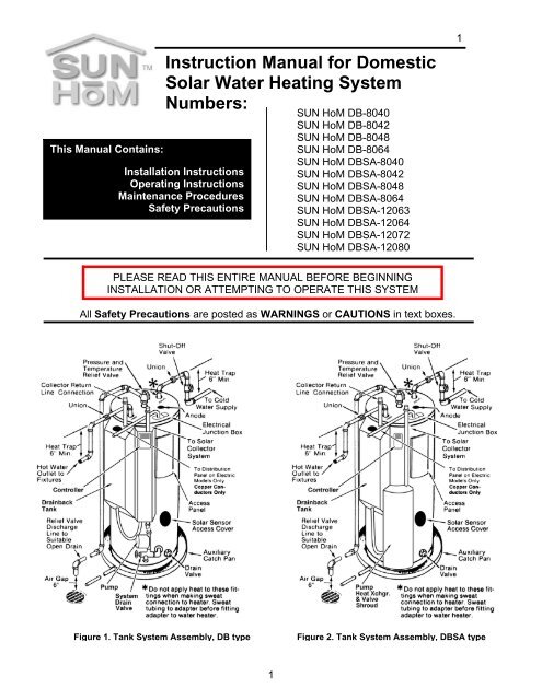
11THIS IS A DRAINBACK SYSTEM. ALL PLUMBINGTO AND FROM COLLECTORS AND THECOLLECTORS THEMSELVES MUST BE SET SOTHEY WILL DRAIN COMPLETELY WHEN THEPUMP IS OFF.It is not recommended that collectors be mountedwith the parallel flow tubes in the horizontalposition. In the event this is the only option, thecollectors must slope downward toward thecollector inlet by no less than ¼” per foot. The Toand From Collector plumbing lines should alsoslope ¼” per foot from the collectors back to thetank.The installation of all horizontal and vertical pipingmay not reduce the per<strong>for</strong>mance or rating of anystructural member or fire rated assembly. Adhere toall applicable local codes and ordinances.Fig. 17Collector Sensor PlacementThe collector sensor must be located on the hotwater return line as close to the collector as possible.Sensors are typically accurate to +/- 1/2°F ifproperly installed and weatherized. To maximizesensor accuracy, attach the flanged portion of thesensor to the SunEarth, Inc. collector header pipe,as close as possible to the collector outlet, with astainless steel hose clamp. Wire nuts used toconnect the sensor and low voltage wiring shall beall plastic, sealed with silicone and thoroughlywrapped in electrician's tape.header. Thoroughly wrap and weatherize theinsulation with electrician's tape or insulation tapeas provided by the manufacturer (Rubatex Insul-Tape or equal). See Figure 17 <strong>for</strong> collector sensorinstallation detail.Low Voltage Wiring:The low voltage wiring used to connect the collectorsensor to the controller should be a minimum18AWG. The wiring should be bare or tinned copper,two conductor, PVC insulated, with a PVC UV ratedgray jacket suitable <strong>for</strong> exterior use. Use EastmanWire & Cable No. 5704, Belden Wire and Cable No.8461 or equal. The system comes pre-wired <strong>for</strong> thetank sensor. Do not attempt to install a tank sensor.Interconnect Plumbing:Piping to and from the solar collector array is calledthe interconnect plumbing. Because the SUN HoMsystem is a Drainback Type it requires minimalplumbing. The main Issue in Drainback systems isthat the interconnect plumbing must slope from thecollectors back to the drainback reservoir with nochange in the slope that would cause water to stayin the lines when the pump is not running.From the two collector interconnect fittings on thetank system assembly only ¾” hard copper pipingshould be used. The proper unions are suppliedwith the system. Measure the distance from the topof these two fittings to a point inside the attic spacesthat is 1¼” above the level of the top of the bottomcord of the roofing trusses. Cut two pieces of hardcopper tubing to this length. Sweat the unionsprovided with the system to two pieces of coppertubing. Using Rubatex pipe insulation cut twopieces the length of the distance from top of theunions to the ceiling where the tubes will penetrate.Install the Rubatex and insert the two pieces oftubing into holes cut directly above the To andReturn Collector fittings on the tank systemassembly. Refer to Figure 1 and 2 <strong>for</strong> the location ofthese fittings.From these two pieces of copper tubing, soft coppertubing can be run in the attic spaces to the pointwhere the piping must transition through the roof.The entire length of the piping should be insulated.The sensor "bundle" must be placed under therubber pipe insulation covering the collector11
Charging the System:Once the components are plumbed you are readyto charge the collector loop. This is done at theDrainback tank on the tank system assembly. It isrecommended that the collector loop be flushed toinsure all solder fluxes and any other contaminantsare not present when the final distilled water chargeis put in. A pre-charge of regular tap water can berun through the collector loop <strong>for</strong> several minutesprior to the final operating charge being installed. Ifthere is evidence of sever contamination in thepiping, tri-sodium phosphate(TSP) can be added tothe tap water charge.If a pre-flush is determined to be needed theDrainback Tank should be filled with regular tapwater to the FILL Line on the side of the tank. Atthis point ¼ to ½ cup of TSP can be added ifnecessary. When ready, plug in the controller. Thepump should be turned on and off several times at5 minute intervals to flush the system piping. Thepump can be turned off and on with the manualswitch located inside the controller front panel.When this is completed drain the solar loop usingthe System Drain Valve below the pump (On DBSAsystems the System Drain Valve is behind theshroud). When the tank is fully drained use a hoseto continue flushing out the drainback tank <strong>for</strong> 5minutes. Turn off the hose and let the system drainfully. Make sure the controller is set back to theautomatic position. Unplug the controller whenfinished.After flushing and the drainback tank is completelydrained, fill the drainback tank to the Fill Line on theside of the tank with pure clean distilled water. If theelection is made to add a gallon of propylene glycolto the system, leave room <strong>for</strong> this when filling thetank. Use of inhibited propylene glycol, plainwater or a concentration of these two fluids asthe Heat Transfer Fluid (HTF) in this system isstrictly prohibited.If propylene glycol is added to the solar loop amethod of checking the heat transfer fluid <strong>for</strong> PHmust be implemented. See “Service” and “SystemParts List” Sections in this manual <strong>for</strong> instruction.OPERATING INSTRUCTIONS12Refer to Figures 1 and 2 or the system schematicsat the end of this manual <strong>for</strong> references in operatingthis system.System Start Up:Drainback type systems are the simplest of theactive type systems to start up. At this point all thatremains is <strong>for</strong> the controller to be plugged into anoutlet. A red light (First one on the left) on the frontof the controller should indicate power is present. Ifnot check to see power is present at the outlet.If sufficient solar energy is present the system willbegin to operate automatically. When the collectoris hotter than the tank by 12 0 F or more the NumberOne light (Center one) on the controller will comeon indicating that power is supplied to the pump.<strong>Water</strong> is lifted by the pump to the collector where itpicks up heat and is returned to the drainback tank.The drainback tank supplies the water to the heatexchanger where it gives up heat energy to thewater heater tank and is then sent back to thecollector by the pump. This cycle continues as longas the collector is hotter than the tank. In “DB” typesystems the heat exchanger is wrapped around thesteel water heater tank so heat energy istransferred by conduction through the tank wall tothe water. In “DBSA” type systems the solar heatedfluid is sent to a “Side Arm” heat exchanger locatedout side the tank jacket. In this type heat exchangerthe solar heat fluid passes around the outside of abundle of vertical tubes that have the potable waterinside them. The heat causes the potable water torise where it moves back into the main tank. Whenthis happens, cold water flows in from the bottomwhere it is heated. This is called a thermo-syphoncycle and it will continue was long as long as heatis available from the collectors.With the pump running, check all lines, fittings andjoints <strong>for</strong> leaks. If leaks are present, unplug thecontroller, wait <strong>for</strong> the HTF to drain back and thenmake repairs. To start up again, plug in thecontroller.Flat plate collectors can reach temperatures over 300 0 Funder the right conditions. Always be cautious whenworking around flat plates that are exposed to sunlight. <strong>Water</strong> passing through tube incorporated in theplate picks up heat to transfer to the water heater.This completes the system installation procedure.12
13Explanation of Major Components and TheirFunction.COLLECTOR:The SunEarth collectors in your SUN HoM systemare flat plate type. They are designed to maximizethe capture of solar energy in the temperatureranges required <strong>for</strong> domestic hot water. Flat platecollectors accomplish this by employing the greenhouse effect. The glass covering permits up to 90%of the visible sunlight to enter the collector. Whenthe light passes through the glass it’s frequency ischanged slightly to a lower energy level. When thelight strikes the absorbing surface of the flat plateinside the light is absorbed as heat. Thecombination of the glass frequency change and thesolar absorbing surface of the plate capture themaximum amount of energy. As the absorber plateheats up it begins to radiate energy as infrared (IR)or heat radiation. Glass is essentially opaque to IRwavelengths so the heat is trapped increasing thetemperature.TANK SYSTEM ASSEMBLY:Unlike most other solar systems your SUN HoMDrainback system comes pre plumbed and wired asa complete assembly. This is called the TankSystem Assembly or TSA. The TSA contains thewater heater tank, the heat exchanger, pumpcontroller, drainback tank, tank sensor, drain valve,system drain valve and the wiring and piping tomake all connections. The TSA, the collectors andthe interconnect piping make up the completesystem.TANK SYSTEM ASSEMBLY: (cont.)• Pump: The system is equipped with a singleTACO 009 or 008 Bronze circulator pump. Ituses 115V regular AC power which is suppliedfrom the controller. When heat is available inthe collector the pump is energized to lift theheat transfer fluid (distilled water) through theinterconnect piping to the collectors where itgains heat. The water then returns to thedrainback tank, then to the heat exchangerwhere it heats the potable water. The cyclecontinues until the collector can no longercontribute heat energy.• Controller: The controller is powered by 115Vhouse current and is the device that determinesif solar energy is available. The controller,through the sensors, constantly measures thetemperature of the water heater tank and thecollector, comparing them to see if the collectoris hotter then the tank. When the collectorreaches a 12 0 F higher temperature than thewater heater tank the controller energizes thepump. As stated above the pump will continueto run until the differential temperature (thedifference between the collector and the tank)drops to 4 0 F. When this happens the pump isturned off and the heat transfer fluid drains backinto the drainback tank.• Sensors: The system contains 2 sensors, oneat the outlet of the collector and one on thebottom of the water heater tank. The controlleruses these 2 sensors to measure tank andcollector temperatures. They are simplethermistor (thermal resistors) type sensors thathave an inverse reaction to temperature. As thetemperature goes, up the resistance goesdown. The controller is calibrated to read this astemperature changes. As the collector heats upthe resistance goes down and at the right pointthe controller turns on the pump. The reversehappens when the collector cools off.• <strong>Water</strong> Heater Tank: This is standard glass linedsteel tank that is constructed just like any otherwater heater. The only difference is that it has aheat exchanger wrapped around the outer steelor it has extra ports to make connections to. Inthe DBHE series systems the heat exchanger isa copper coil wrapped around the lower half ofthe tank be<strong>for</strong>e it is insulated. In the DBSAseries, the tank has side ports and the heatexchanger is external to the tank. In eithersystem the heat exchanger is used to transfersolar heat energy to the potable water.• Heat Exchanger: An all copper device used totransfer solar heat to the potable water. See“System Start Up” section above <strong>for</strong> more detailon how this works.• Temperature and Pressure Relief Valve: Thisdevice is inserted into the water heater tank <strong>for</strong>safety. It is located on top of the tank. The T&Prelief valve is preset to open and discharge ifeither a high pressure or high temperaturesituation occurs in the water heater. All waterheaters regardless of whether they are solarpower or not, must have this safety devicewhich is required by national building codes.There is no T&P valve required in the collectorloop as it is a non-pressurized type.• Isolation Valve: Also called “Shut Off Valve”,this valve is installed in the cold water service13
14line to the water heater. It is used to isolate thesystem <strong>for</strong> maintenance, repairs and service.THIS VALVE SHOULD ALWAYS BE OPEN IFELECTRIC POWER IS ON TO THE HEATINGELEMENT IN THE WATER HEATER TANK.Other types of solar water heating systemshave collector isolation valves. Since thissystem employs Drainback freeze protection.the system does not have collector loopisolation valves.• Drainback Tank: This is a vented reservoir tankattached to the side of the water heater tankthat holds the collector loop heat transfer fluid(HTF). (The vent is in the cap supplied with thesystem) This system uses distilled water <strong>for</strong> theHTF. When the pump is turned on water isdrawn from the drainback tank and supplied tothe collectors. When the water returns it entersthe drainback tank through a copper dip tubethat is inserted into the top of the drainbacktank. This copper dip tube is a very importantpart of the systems and cannot be replaced bya simple tube. It has been pre-cut and drilled toper<strong>for</strong>m a precise function. It is extremelyimportant <strong>for</strong> the water to enter thedrainback tank below the water level in thetank. If it does not, serious damage or injurycan occur.• Freeze Prevention: The system uses theprinciple of draining water from the collectors toprevent freezing. No other valves, controlfunctions or devices are required to preventfreezing of the collectors. When the pump is deenergizedthe water in the collector loop drainsback to the Drainback Tank thereby preventingcollector freeze damage. Proper installation iskey to insuring this type freeze protectionworks.• Heat Transfer Fluid: This is the liquid added toand stored in the Drainback Tank. Distilledwater is the recommended fluid. Use of potabletap water is prohibited. As described earlier,propylene glycol can be added at a ratio of 8:1,(8 parts water to one part propylene glycol).This is not required.SERVICE:START UP PROCEDURE: At this point the waterheater tank should already be filled and on line <strong>for</strong>hot water. This includes the electric elementconnections.1. Fill the Drainback Tank to the level indicated onthe side of the cover.2. Insure all connections, both plumbing andelectrical have been made. Plumbingconnections include the To and From piping tothe collector. The electrical connection is thesensor wire from the collector sensor to thecontroller.3. Plug in the controller.If sufficient solar energy is available the pumpshould come on right away.DO NOT TEST THE RETURN LINE FOR HEAT BYTOUCHING IT WITH YOUR BARE HAND.This is the end of the start up procedure.SHUT DOWN PROCEDURE: Depending on therequirement, not every step needs to be followed.1. Unplug the controller.2. If required, attach a hose to the System DrainValve. See Figures 1 and 2.3. Open the System Drain Valve and drain HTF toa container if it has the propylene glycoladditive. If not discharge the HTF to a drain orground.SYSTEM HTF CAN BE HOT. USE CAUTION!!!This is the end of the shut down procedureIf the water heater tank is to be shut downfollow these steps only after the Shut DownProcedure <strong>for</strong> the solar system has beencompleted.1. Disconnect electric power to the water heater.(Throw the breaker.)2. Close the Shut Off Valve.3. If the water heater tank needs to be drained:Attach a hose to the Drain Valve on the bottomof the water heater.4. Open the drain valve.5. Open the T&P relief valve to allow the tank tovent. The T&P valve can be opened by liftingthe lever on top to the vertical position.To recharge the water heater tank follow theinstructions contained in the Installation section.14
15OPERATIONAL CHECK: If hot water is beingsupplied the system is obviously producing it. It maynot be clear whether the heat is being supplied bythe electric element, or by the solar collectors.Follow this procedure to check <strong>for</strong> solar systemoperation.1. During bright sunlight check to see if theNumber “1” indicator light on the controller ison. (This is the center red light in the lower righthand corner.) If it is the pump should berunning and the drainback reservoir should bewarm or hot to the touch. This step only showsthe controller and pump are working.2. Check to see the pump is not running at night. Ifit is consult the troubleshooting guide. Whenfinished locating problem and repairs have beenmade, repeat this step.3. In the morning, disconnect power to the electricbackup element in the water heater. (DO THISBY THROWING THE BREAKER).4. At the end of the day check to see if quantitiesof hot water are available.During summer months it may be possible tocompletely turn off power to the back up element.This is done by throwing the breaker. This isrecommended only after it is determined the solarsystems is supplying hot water.SYSTEM FLUID CHECK: A periodic inspection ofthe system to check the HTF level is recommended.Every month the level should be checked to see it iswithin 2” of the Fill Line. If the level drops simplyadd distilled water to bring it back up to the Fill Line.If the option of adding propylene glycol to the HTFis elected, a monthly check of the PH of the HTF isrequired. Using PH strips such as those used <strong>for</strong>swimming pools, or by using a digital PH meter areacceptable methods <strong>for</strong> per<strong>for</strong>ming the PH check. Ifthe PH drops below “7”, follow the Shut DownProcedure and drain the HTF. Then, repeat theStart Up Procedure. (See also ChargingProcedure.)MAINTENANCE:WATER HEATER TANK: Once each year it isrecommended that the water heater tank be purged.To do this, follow the steps below.1. Disconnect power to the electric element.(DO THIS BY THROWING THE CIRCUITBREAKER)2. Attach a hose to the Drain Valve on thebottom of the water heater tank.3. See Figures 1 and 2. Open the Drain Valveslowly to allow water under line pressure topurge the tank <strong>for</strong> a few minutes.4. Close the “Shut off Valve”.5. Let the system set <strong>for</strong> 10 minutes, Thisallows the sediment to fall back to thebottom of the tank.6. Now open the T&P relief valve to allowsediment particles to drain out by gravity.7. Let this continue until the discharge at theend of the hose is clear water. Whenfinished follow the next series of stepsexactly.1. Close the T&P Valve.2. Close the Drain Valve and remove thehose.3. Open the system Shut Off Valve.4. Open a hot water faucet in the highest partof the home.5. Wait until a stream of clear water runs <strong>for</strong>several minutes with no air escaping.6. Return power to the backup element.SOLAR SYSTEM MAINTENANCE: Drainback typesystems are the most trouble free systemsavailable. The only maintenance required is tocheck and insure the level and PH of the heattransfer fluid in the Drainback Tank are kept withinproper limits. See “SYSTEM FLUID CHECK” underSERVICE.COLLECTOR MAINTENANCE: Collectors operatebest when the glass is clean and unobstructed. Ifthey become dirty wash them with mild soapy waterand rinse. Remove any branches or leaves that donot naturally fall off or are blown away by the wind.Collectors installed at the proper angle anywhere inthe continental United States should not have eitherof these problems. Dust and dirt build can be aproblem in dry desert climates where there is littlerain to wash the glass.15
16TROUBLESHOOTING:Follow the chart below <strong>for</strong> problem identification andresolution:SYMPTOM CHECK REPAIRNo hot waterPump “On”light is lit,pump doesnot run.Pump andcontrollerwork but nohot water.<strong>Water</strong> is tooHOT.Check to seepower is on tobackup elementPer<strong>for</strong>m solarsystemoperationalchecksIf election is madeto operate on“<strong>Solar</strong> Only”Check HTF levelin drainback tankUnplug pumppower line fromcontroller andplug into 115Vextension cordCheck <strong>for</strong>sufficient sunlight.Check to insureproper flow insolar loop.If solar loop isworking properlybut sunlight is notavailable thencheck electricbackup element.Check high limitsetting on solarcontroller.If solar suppliedwater is atpreferredtemperatureRe-engagepower. If power ison replaceelement.If pump does notfunction, replaceit. If controller isnot working,Check sensorsand replace ifnecessary. Ifcontroller doesnot work, replaceit.Check to insuresufficient sunlighthas beenavailable.If low, adddistilled water.If pump runs,replace controller,if not replacepump cartridge orcapacitor.If no sun light isavailable, reapplypower to electricbackup element.If HTF water isnot flowing callsolar contractorwho installed thesystem <strong>for</strong> serviceReplace electricelement.Reduce setting iftoo high.Install optionaltempering valvebetween cold andhot lines on waterheater.SYMPTOM CHECK REPAIRNO lights on,on controllerUnsure ofsystemper<strong>for</strong>mance.Check <strong>for</strong>thermostat failureon electricelement.Check to insureunit is plugged in.If bad replace it.If plugged inreplace unit orcall technicianCall systeminstaller.Additional Troubleshooting procedures <strong>for</strong> solarsystems can be found at the Florida <strong>Solar</strong> EnergyCenter web site:http://www.fsec.ucf.edu/solar/apps/sdhw/trouble.htmSYSTEM PARTS LIST:System Part Number:Each SUN HoM system is identified by a systempart number, i.e.: DBSA 80-40. The letters refer to:DrainBack Type Heat Exchanger type:“DB” only means Heat Exchange Tank“DBSA” stands <strong>for</strong> Side Arm Heat ExchangerThe first two or three number designators, (i.e.: 80or 120) stand <strong>for</strong> the tank size in gallons. Thesecond two number designators indicate collectorsquare footage, (i.e.: 40).The table below indicates collector type based onthe square footage number. Collectors aremanufactured and supplied by SunEarth, Inc.Designator BRAND Sq. Ft. Part # NO.40 Empire 40 EP-40 142 Empire 21 EP-21 248 Empire 24 EP-24 263 Empire 21 EP-21 364 Empire 32 EP-32 272 Empire 24 EP-24 380 Empire 40 EP-40 216
17Parts Number List:All parts available through <strong>Solar</strong>Direct.com, or<strong>Solar</strong> Direct, 5919 21 st Street E, Bradenton,Florida 34203. Ph: 941-359-8228<strong>Water</strong> Heater Tank: RUUD, RSPE-80-1 <strong>for</strong> DBSAmodels, RSPER-HE-1 <strong>for</strong> DB models.Collectors: See table above.Pump: TACO 009B or 008B CirculatorDrainback Tank: <strong>Solar</strong> Energy, Inc., DB-TankController: Goldline, GL-30 LC.Sensors: Goldline, SB sensor.Propylene Glycol: Dow Frost (R)Other parts have multiple options <strong>for</strong> replacement.number it will NOT BE HONORED. If it is anemergency and the part is needed right away, youmay call the company at 1-941-359-8228 to file aclaim. The original system serial number must beavailable at the time the claim is made. All otherclaims should be sent by mail.This system is provided by:<strong>Solar</strong> Direct5919 21 st Street EastUnit ABradenton, Florida 34203Phone: 800—333- 9276FAX: 941-359-8228http://www.<strong>Solar</strong>Direct.comLIMITED WARRANTY:This system is covered under Limited Warranty by<strong>Solar</strong> Energy, Inc. Its coverage only extends to thelimits of coverage of materials and workmanship ofsystem components that are not covered byWarranty from or by the OEM manufacturer of theindividual components. Individual Warranties <strong>for</strong> thecomponents are supplied with the system when it isdelivered. Please consult the individual warrantycards be<strong>for</strong>e making a claim to <strong>Solar</strong> Energy, Inc.Limits of Coverage: <strong>Solar</strong> Energy, Inc. willreplace or repair any part in the system <strong>for</strong> a periodof five (5) years from the date of initial purchasesubject to the following Terms and Conditions.1. The part does not have a Warranty supplied byanother company that covers the part.2. The part was installed in the initial assembly.3. The part became defective as result of normaluse.This Limited Warranty does not extend anyWarranty, written or implied by others withrespect to time or limits of coverage. ThisLimited Warranty does not cover valves.“The solar system described by this manual,when properly installed and maintained, meetsthe standards established by the Florida <strong>Solar</strong>Energy Center, in accordance with Section377.705, Florida Statutes. This certification doesnot imply endorsement or warranty of thisproduct by the Florida <strong>Solar</strong> Energy Center orthe State of Florida.”For Service Call:How To File a Claim:A Warranty Card is supplied with the system when itis sold. THIS CARD MUST BE FILLED OUT ANDRETURNED AT THE TIME OF SALE. TheWarranty Card has two sections. Fill out bothsections and separate the two halves. Mail the halfthat has the address on the back side and keep theother <strong>for</strong> your records.When filing a claim with <strong>Solar</strong> Energy, Inc., use thesystem serial number on the retained part of theWarranty Card. If a claim does not have this17