The NuSTAR Data Analysis Software Guide - HEASARC - NASA
The NuSTAR Data Analysis Software Guide - HEASARC - NASA
The NuSTAR Data Analysis Software Guide - HEASARC - NASA

Create successful ePaper yourself
Turn your PDF publications into a flip-book with our unique Google optimized e-Paper software.
<strong>The</strong> <strong>NuSTAR</strong> <strong>Data</strong> <strong>Analysis</strong> <strong>Software</strong> <strong>Guide</strong> M. Perri, S. Puccetti, N. Spagnuolo (ASI Science <strong>Data</strong> Center) & A. Davis, K. Forster, B. Grefenstette, F. Harrison, K. Madsen (California Institute of Technology) Version 1.7 May 2014
<strong>The</strong> <strong>NuSTAR</strong> <strong>Data</strong> <strong>Analysis</strong> <strong>Software</strong> <strong>Guide</strong>Document HistoryVersion Date Comment1.0 August 18, 2012 First version1.1 September 21, 2012 Revised and updated for <strong>NuSTAR</strong>DAS v. 0.6.11.2 October 31, 2012 Revised and updated for <strong>NuSTAR</strong>DAS v. 0.8.01.3 August 29, 2013 First public version, revised and updated for <strong>NuSTAR</strong>DAS v. 1.2.01.4 November 21, 2013Revised and updated for <strong>NuSTAR</strong>DAS v. 1.3.0. Addition ofanalysis cases section 6.1.5 December 13, 2013 Revised and updated for <strong>NuSTAR</strong>DAS v. 1.3.1.1.6 April 23, 2014 Revised and updated for <strong>NuSTAR</strong>DAS v. 1.4.0.1.7 May 30, 2014 Revised and updated for <strong>NuSTAR</strong>DAS v. 1.4.1.Table 1-1: Document History<strong>NuSTAR</strong> <strong>Software</strong> <strong>Guide</strong> 3
<strong>The</strong> <strong>NuSTAR</strong> <strong>Data</strong> <strong>Analysis</strong> <strong>Software</strong> <strong>Guide</strong><strong>NuSTAR</strong> <strong>Software</strong> <strong>Guide</strong> 4
<strong>The</strong> <strong>NuSTAR</strong> <strong>Data</strong> <strong>Analysis</strong> <strong>Software</strong> <strong>Guide</strong>Contents1 INTRODUCTION ............................................................................................................................................................. 9 1.1 Scope ....................................................................................................................................................................... 9 1.2 <strong>Software</strong> Characteristics .......................................................................................................................................... 9 1.3 <strong>Software</strong> Breakdown ................................................................................................................................................ 9 1.4 Downloading and installing .................................................................................................................................... 11 1.5 <strong>Guide</strong> Organization ................................................................................................................................................ 12 2 <strong>NuSTAR</strong> DATA FILES ................................................................................................................................................... 13 2.1 <strong>NuSTAR</strong> File Naming Convention .......................................................................................................................... 13 2.2 Archive Directory Structure .................................................................................................................................... 13 3 DATA CALIBRATION (STAGE 1) .................................................................................................................................. 17 3.1 Standard <strong>Data</strong> Processing with 'nupipeline' (Stage 1) ........................................................................................... 17 3.2 Metrology <strong>Data</strong> Processing ('numetrology') ........................................................................................................... 18 3.3 Attitude File Correction ('nuattcorr')........................................................................................................................ 19 3.4 Bad Pixels Flagging ('nuflagbad')........................................................................................................................... 19 3.5 Hot Pixels Searching and Flagging ('nuhotpix')...................................................................................................... 21 3.6 Energy Corrections, Event Reconstruction and GRADE Assignment ('nucalcpha') .............................................. 22 3.7 Gain Correction ('nucalcpi') .................................................................................................................................... 25 3.8 Events Flagging ('nuflagevt') .................................................................................................................................. 26 3.9 Coordinates Transformation ('nucoord')................................................................................................................. 27 3.9.1 Detector Coordinates Calculation ('nucalcpos')........................................................................................... 28 3.9.2 Sky Coordinates Calculation ('coordinator') ................................................................................................ 29 3.9.3 Optical Axis, Aperture Stop Center and Detector Reference Pixel Sky Positions ('nuskypos')................... 30 4 EVENTS SCREENING AND EXPOSURE MAPS GENERATION (STAGE 2) .............................................................. 33 4.1 Standard <strong>Data</strong> Processing with 'nupipeline' (Stages 1 and 2) ............................................................................... 33 4.2 Rationale ................................................................................................................................................................ 34 4.3 SAA passages calculation ('nucalcsaa')................................................................................................................. 34 4.4 Filter File Generation ('nufilter') .............................................................................................................................. 35 4.5 Good Time Intervals Generation and <strong>Data</strong> Screening ('nuscreen')........................................................................ 36 4.6 Dead Time Correction ('nulivetime') ....................................................................................................................... 37 4.7 Screening criteria ................................................................................................................................................... 38 4.7.1 Screening Criteria associated with the attitude and orbital parameters ...................................................... 38 4.7.2 Screening Criteria associated with the mast position .................................................................................. 38 4.7.3 Screening Criteria associated with the instrumental parameters ................................................................ 39 <strong>NuSTAR</strong> <strong>Software</strong> <strong>Guide</strong> 5
<strong>The</strong> <strong>NuSTAR</strong> <strong>Data</strong> <strong>Analysis</strong> <strong>Software</strong> <strong>Guide</strong>4.7.4 Standard Screening Expressions for attitude/orbital/instrumental parameters ........................................... 39 4.7.5 Screening Criteria associated with the event proprieties ............................................................................ 40 4.7.6 SCIENCE observational mode: summary. .................................................................................................. 41 4.8 Examples of how to screen the data with custom selections ................................................................................. 42 4.8.1 Example of how to use 'nuscreen'............................................................................................................... 42 4.8.2 Example of how to use nupipeline ............................................................................................................... 42 4.9 Generation of Exposure Maps ('nuexpomap')........................................................................................................ 42 4.9.1 Exposure maps generation in 'nupipeline'.................................................................................................. 44 4.10 Trasformation of SKY coordinates in DET1 and DET2 coordinates ('nuskytodet') ................................................ 45 5 EXTRACTION OF PRODUCTS (STAGE 3) .................................................................................................................. 47 5.1 Standard <strong>Data</strong> Processing with 'nuproducts' (Stage 3) .......................................................................................... 48 5.2 Standard <strong>Data</strong> Processing with 'nupipeline' (Stages 1, 2 and 3) ........................................................................... 49 5.3 <strong>The</strong> Extraction of high-level data products ('nuproducts') ...................................................................................... 49 5.4 <strong>The</strong> Extraction of high-level data products with 'nupipeline'................................................................................... 54 5.5 Apply backscale correction to energy spectra ('nubackscale')............................................................................... 55 5.6 Apply livetime, PSF/EXPOSURE and vignetting corrections to light-curves ('nulccorr') ........................................ 56 5.7 Generation of ARF files ('numkarf') ........................................................................................................................ 58 5.8 Generation of RMF files ('numkrmf') ...................................................................................................................... 60 6 SPECIFIC ANALYSIS CASES ...................................................................................................................................... 61 6.1 Standard Processing .............................................................................................................................................. 61 6.2 Generation of high-level data products with a user defined temporal filter ............................................................ 62 6.3 Metrology data out of range: recovery of lost exposure time ................................................................................. 62 6.4 Barycenter Correction ............................................................................................................................................ 63 6.4.1 Method 1: Level 3 files correction with 'nuproducts' .................................................................................... 63 6.4.2 Method 2: light-curve correction with 'barycorr' ........................................................................................... 64 7 CALIBRATION FILES .................................................................................................................................................... 65 7.1 Introduction ............................................................................................................................................................ 65 7.2 List of calibration files used by <strong>NuSTAR</strong>DAS ......................................................................................................... 65 8 APPENDIX A: FITS FILE STRUCTURE ........................................................................................................................ 67 8.1 Level 1 File Format ................................................................................................................................................. 67 8.2 Level 1a File Format ............................................................................................................................................... 68 8.3 Level 2 File Format ................................................................................................................................................. 69 8.4 GTI table FITS Format ........................................................................................................................................... 71 8.5 Bad Pixel table FITS Format .................................................................................................................................. 71 8.6 Filter File Format .................................................................................................................................................... 72 8.7 Optical Axis File Format ......................................................................................................................................... 73 <strong>NuSTAR</strong> <strong>Software</strong> <strong>Guide</strong> 6
<strong>The</strong> <strong>NuSTAR</strong> <strong>Data</strong> <strong>Analysis</strong> <strong>Software</strong> <strong>Guide</strong>8.8 DET1 Reference Pixel File Format ......................................................................................................................... 74 8.9 Mast aspect solution File Format ........................................................................................................................... 74 8.10 Position Sensing Detector File Format ................................................................................................................... 75 Index of TablesTable 1-1: Document History ................................................................................................................................................... 3Table 7-1: Calibration Files .................................................................................................................................................... 63Table 8-1: Level 1 FITS File structure ................................................................................................................................... 67Table 8-2: Level 1 FITS File Events Table Columns ............................................................................................................. 67Table 8-3: Level 1a FITS File structure ................................................................................................................................. 68Table 8-4: Level 1a FITS File Events Table Columns ........................................................................................................... 69Table 8-5: Level 2 FITS File structure ................................................................................................................................... 69Table 8-6: Level 2 FITS File Events Table Columns ............................................................................................................. 71Table 8-7: GTI Table columns ............................................................................................................................................... 71Table 8-8: Bad Pixels Table columns .................................................................................................................................... 71Table 8-9: Filter FITS File structure ....................................................................................................................................... 72Table 8-10: Filter Table Columns .......................................................................................................................................... 73Table 8-11: Optical Axis FITS File structure .......................................................................................................................... 73Table 8-12: Optical Axis Table Columns ............................................................................................................................... 73Table 8-13: DET1 Reference Pixel FITS File structure ......................................................................................................... 74Table 8-14: DET1 Reference Pixel Table Columns ............................................................................................................... 74Table 8-15: Mast aspect solution FITS File structure ............................................................................................................ 74Table 8-16: Mast aspect solution Table Columns ................................................................................................................. 74Table 8-17: Position Sensing Detector FITS File structure ................................................................................................... 75Table 8-18: Position Sensing Detector Table Columns ......................................................................................................... 75Index of FiguresFigure 1: <strong>NuSTAR</strong>DAS data reduction flow diagram ............................................................................................................. 10 Figure 2: Definition of the <strong>NuSTAR</strong> event grades ................................................................................................................. 24Figure 3: Relationship between the raw telemetry coordinates of the four sub-detectors (coordinates 'RAWX', 'RAWY')and the Focal Plane Bench Frame (coordinates 'DET1X', 'DET1Y'). .................................................................................... 28Figure 4: Relationship between the detector coordinates in the Focal Plane Bench frame (columns 'DET1X','DET1Y')and in the Optics Bench frame (columns 'DET2X', 'DET2Y'). ............................................................................................... 29 <strong>NuSTAR</strong> <strong>Software</strong> <strong>Guide</strong> 7
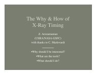
<strong>The</strong> <strong>NuSTAR</strong> <strong>Data</strong> <strong>Analysis</strong> <strong>Software</strong> <strong>Guide</strong>1 INTRODUCTION1.1 ScopeThis <strong>Guide</strong> describes the <strong>NuSTAR</strong> <strong>Data</strong> <strong>Analysis</strong> <strong>Software</strong> (<strong>NuSTAR</strong>DAS), the software for the processingof scientific data taken with the <strong>NuSTAR</strong> observatory. In this guide the processing procedures for thecalibration, the screening and the generation of high-level <strong>NuSTAR</strong> data products (energy spectra, lightcurves,sky images) to be used for scientific analysis are discussed. <strong>The</strong> <strong>NuSTAR</strong>DAS package has beenjointly developed by the ASI Science <strong>Data</strong> Center (ASDC, Italy) and the California Institute of Technology(Caltech, USA).This document does not provide a description of the <strong>NuSTAR</strong> observatory and of its scientific payload forwhich the reader is referred to the primary mission description document (Harrison et al., 2013, ApJ, 770,103). This guide is a living document, following the evolution of the processing algorithms, the calibrationinformation and the data analysis techniques. This version of the guide is written based on version 1.4.1 ofthe <strong>NuSTAR</strong>DAS package and version 20140414 of the <strong>NuSTAR</strong> CALDB. It will be regularly updatedfollowing the future software changes.1.2 <strong>Software</strong> Characteristics<strong>The</strong> <strong>NuSTAR</strong>DAS package produces cleaned, calibrated event list files and standard high-level scientificproducts starting from the FITS formatted telemetry data. <strong>The</strong> software is designed as a collection ofsoftware modules (tasks) each dedicated to a single function. <strong>The</strong> package includes also a main script, the<strong>NuSTAR</strong> pipeline (named 'nupipeline') allowing users to automatically run in sequence all the tasks for thedata processing.<strong>The</strong> <strong>NuSTAR</strong> tasks are written in FTOOLS style and the whole package is fully compatible with theHEASoft software, maintained and distributed by the <strong>NASA</strong>-<strong>HEASARC</strong> data center(http://heasarc.gsfc.nasa.gov). <strong>The</strong> <strong>NuSTAR</strong>DAS package is officially integrated in the HEASoftand distributed to the users within its standard public releases. Questions about the <strong>NuSTAR</strong>DAS softwarepackage can be addressed to the <strong>HEASARC</strong> help desk at http://heasarc.gsfc.nasa.gov/cgibin/Feedbackwhere you should select “<strong>NuSTAR</strong>” as the mailing list.Multi-mission FTOOLS from the HEASoft package are also used in several <strong>NuSTAR</strong>DAS modules. <strong>The</strong><strong>NuSTAR</strong> software parameter interface is implemented with the PIL (Parameter Interface Library) libraryand the I/O with the FITS data files makes use of the FITSIO library.<strong>The</strong> <strong>NuSTAR</strong> software tasks retrieve the calibration files structured in <strong>HEASARC</strong>'s calibration database(CALDB) system. <strong>The</strong> <strong>NuSTAR</strong>DAS data processing software uses FITS data format following the <strong>NASA</strong>-OGIP standards as inputs and outputs and makes exclusive use of open source software (C and Perllanguages).1.3 <strong>Software</strong> Breakdown<strong>The</strong> input to the <strong>NuSTAR</strong>DAS package is the <strong>NuSTAR</strong> FITS formatted telemetry data produced at the<strong>NuSTAR</strong> Science Operation Center (<strong>NuSTAR</strong> SOC) in Caltech. <strong>The</strong> <strong>NuSTAR</strong>DAS data processing isorganized in three distinct stages for the calibration, the screening and the extraction of high-level scientificproducts as illustrated in Fig. 1 showing the <strong>NuSTAR</strong>DAS high-level data reduction flow diagram.<strong>NuSTAR</strong> <strong>Software</strong> <strong>Guide</strong> 9
<strong>The</strong> <strong>NuSTAR</strong> <strong>Data</strong> <strong>Analysis</strong> <strong>Software</strong> <strong>Guide</strong>Figure 1: <strong>NuSTAR</strong>DAS data reduction flow diagram<strong>NuSTAR</strong> <strong>Software</strong> <strong>Guide</strong> 10
<strong>The</strong> <strong>NuSTAR</strong> <strong>Data</strong> <strong>Analysis</strong> <strong>Software</strong> <strong>Guide</strong><strong>The</strong>se three main processing stages are:1. <strong>Data</strong> Calibration: FITS formatted telemetry processing to produce calibrated event files (Stage 1);2. <strong>Data</strong> Screening: calibrated event files filtering by applying cleaning criteria on specifiedorbital/instrument parameters and event properties to produce cleaned event files (Stage 2);3. Products Extraction: generation of high-level scientific products (light-curves, energy spectra, skyimages, Ancillary Response Files, Redistribution Matrix Files) (Stage 3).<strong>The</strong> processing steps listed above defines the following levels of science data:- Level 0: Raw Telemetry packets;- Level 1: Telemetry formatted in FITS format;- Level 1a: Calibrated Events Files;- Level 2: Cleaned and Calibrated Event Files;- Level 3: High-level Scientific Products (e.g. light-curves, energy spectra, sky images).<strong>The</strong> files generated with the <strong>NuSTAR</strong>DAS package (e.g. Level 1a/2 event files, Level 3 energy spectra andlight-curves) can be read into widely used high-energy astronomy multi-mission data analysis programssuch as XSELECT, XSPEC, XRONOS and XIMAGE.<strong>The</strong> <strong>NuSTAR</strong>DAS package is run at the <strong>NuSTAR</strong> SOC in Caltech where it is used to generate the differentlevels of <strong>NuSTAR</strong> scientific archive. <strong>The</strong> package has also been designed to allow users to reproduce anystage of the data processing which could be necessary, for example, because of improved calibrationinformation, updated software modules or because the user wants to use a non-standard data processing.To this end, the 'nupipeline' script is the main interface for the users.Once installed, specific help files for all the <strong>NuSTAR</strong>DAS modules can be viewed by using the command’fhelp task_name’ (e.g. 'fhelp nupipeline').1.4 Downloading and installing<strong>The</strong> <strong>NuSTAR</strong>DAS package is integrated in the <strong>NASA</strong>-<strong>HEASARC</strong> HEASoft software and can bedownloaded at the following link:http://heasarc.gsfc.nasa.gov/docs/software/lheasoft/<strong>The</strong> installation instructions can be found at the same address. Note that the <strong>NuSTAR</strong> calibration dataprovided in the CALDB must be installed in order to processing the <strong>NuSTAR</strong> scientific data. <strong>The</strong> <strong>NuSTAR</strong>CALDB can be downloaded from:http://heasarc.gsfc.nasa.gov/FTP/caldb/data/nustar/fpm/goodfiles_nustar_fpm.tar.gzDetailed installation instructions are available at:http://heasarc.gsfc.nasa.gov/docs/heasarc/caldb/install.htmlNote that the <strong>NuSTAR</strong> CALDB can be accessed remotely over the internet without having to download thecalibration data locally; for instructions see:http://heasarc.gsfc.nasa.gov/docs/heasarc/caldb/caldb_remote_access.htmlNote that remote access may be slower than accessing the CALDB from a local installation.<strong>NuSTAR</strong> <strong>Software</strong> <strong>Guide</strong> 11
<strong>The</strong> <strong>NuSTAR</strong> <strong>Data</strong> <strong>Analysis</strong> <strong>Software</strong> <strong>Guide</strong>1.5 <strong>Guide</strong> OrganizationThis guide is organized as follows. Chapter 2 describes the <strong>NuSTAR</strong> data files to provide a basicknowledge of their content, the file naming convention and the archive structure. Chapter 3 gives adescription of the processing steps and the software modules involved in the data calibration (Stage 1).Chapter 4 describes the standard screening criteria that are applied to the data and the specific softwaremodules used to produce calibrated and cleaned event files and sky exposure maps (Stage 2). In chapter 5the third stage of the data reduction, i.e. the generation of high-level data products (e.g. energy spectra,light-curves and sky images), is illustrated. Examples of standard data processing command lines andprocedures for some specific analysis issues are given in Chapter 6. In Chapter 7 the calibration files usedin the data processing are described. Finally, the appendix details the table formats for the <strong>NuSTAR</strong>science files.<strong>NuSTAR</strong> <strong>Software</strong> <strong>Guide</strong> 12
<strong>The</strong> <strong>NuSTAR</strong> <strong>Data</strong> <strong>Analysis</strong> <strong>Software</strong> <strong>Guide</strong>2 <strong>NuSTAR</strong> DATA FILES<strong>The</strong> <strong>NuSTAR</strong>DAS data processing software uses FITS data format following the <strong>NASA</strong>-OGIP standards asinputs and outputs. In this chapter we provide a basic knowledge of the file naming convention adopted for<strong>NuSTAR</strong>, their content and how they are located in the <strong>NuSTAR</strong> archive structure.2.1 <strong>NuSTAR</strong> File Naming Convention<strong>The</strong> file name format for the <strong>NuSTAR</strong> science files uses the following convention:where:nuObservationID [M][xx]_[ll].ss• 'nu' is a prefix to indicate the mission name (<strong>NuSTAR</strong>);• 'ObservationID' is a 11 digits number to identify the observation (hereafter obsID);• 'M' is a one character string that identifies the focal Plane Module (A or B);• 'xx' is a code to identify the observing mode as defined below:- 01 (SCIENCE): normal observing scientific mode;- 02 (OCCULTATION): Earth in the field of view;- 03 (SLEW): data taken during a spacecraft slew;- 04 (SAA): South Atlantic Anomaly passages;- 05 (CALIBRATION): on-board calibration radioactive source in the field of view;- 06 (SCIENCE_SC): attitude reconstruction from the spacecraft bus star trackers;• 'll' indicates for event files the processing level ('uf' for Level 1 and Level 1a files, 'cl' for Level 2files). For other data files it describes their content (e.g. 'met' for raw metrology data, 'mast' formast aspect solution file, 'ex' for exposure maps);• 'ss' is the file extension and indicates the data type (e.g. 'evt' for event files, 'img' for sky images,'hk' for housekeeping files, 'lc' for light-curves, 'pha' for energy spectra).<strong>The</strong> quantities in square brackets can be omitted, for example i) 'M' (A or B) is not used for data files fromthe metrology laser system and ii) the observing mode code 'xx' is not used for Level 1/1a event files sincethe data splitting is carried out during the Stage 2 (see Chapter 4).2.2 Archive Directory Structure<strong>The</strong> <strong>NuSTAR</strong> public data archive can be accessed at the <strong>HEASARC</strong>:http://heasarc.gsfc.nasa.gov/FTP/nustar/data/obs/and at the ASDC:http://www.asdc.asi.it/mmia/index.php?mission=numasterFor each observation, the <strong>NuSTAR</strong> science data files are stored in the archive in a single directory namedafter the observationID number. Each directory has the following structure:\observationID\auxil \hk \event_uf \event_cl<strong>NuSTAR</strong> <strong>Software</strong> <strong>Guide</strong> 13
<strong>The</strong> <strong>NuSTAR</strong> <strong>Data</strong> <strong>Analysis</strong> <strong>Software</strong> <strong>Guide</strong>Event files from both focal plane modules, housekeeping, metrology and other types of data (e.g. attitudeand orbit files) are contained in different sub-directories according to their content and/or level ofprocessing as detailed below. <strong>The</strong> obsID 10012001002 (3C 273 calibration observation in July 2012) isused as an example.<strong>The</strong> data archive may also contain files generated during standard data processing of each observationIDat the <strong>NuSTAR</strong> Science Operations Center at Caltech. <strong>The</strong>se files are not used as input to any<strong>NuSTAR</strong>DAS modules.• pipe.log Log of the output from nupipeline processing• nu10012001002.cat.gz Catalog of files in the archive<strong>The</strong> standard pipeline processing log may be useful for comparison to the STDOUT during execution of<strong>NuSTAR</strong>DAS modules.<strong>The</strong> following lists contain all the input files used for the <strong>NuSTAR</strong>DAS data processing.1. <strong>The</strong> 'auxil' directory stores the following files:• nu10012001002_att.fits Corrected star tracker attitude file• nu10012001002_orb.fits Orbit file• NUSTAR_TLE_ARCHIVE.txt.YYYYDDD <strong>NuSTAR</strong> Two-Line Elements file2. In the 'hk' directory the following housekeeping FITS files are contained:• nu10012001002_ceb.hk Central Electronics Box (CEB) housekeeping file• nu10012001002A_fpm.hk FPMA instrument housekeeping file• nu10012001002B_fpm.hk FPMB instrument housekeeping file• nu10012001002A_dspx.fits FPMA disabled pixel map file• nu10012001002B_dspx.fits FPMB disabled pixel map file• nu10012001002_met.fits Raw Metrology <strong>Data</strong> file• nu10012001002_chu123.fits Spacecraft bus star tracker housekeeping file• nu10012001002_chu4.fits Optical bench star tracker housekeeping file• nu10012001002_eng.hk Spacecraft bus attitude quaternion file• nu10012001002_obeb.hk Optical Bench Electronics Box housekeeping file3. <strong>The</strong> 'event_uf' directory stores the Level 1 science event files:• nu10012001002A_uf.evt L1 FPMA event file• nu10012001002B_uf.evt L1 FPMB event file<strong>The</strong> 'event_cl' directory of the archive stores the output files generated by a full processing (Stages 1, 2and 3). A full list of the output files generated by a standard run of the 'nupipeline' script is given below.Note that in the public archive the processed attitude file and the instrument housekeeping files are locatedin the 'auxil' and 'hk' directories, respectively (see individual footnotes).<strong>NuSTAR</strong> <strong>Software</strong> <strong>Guide</strong> 14
<strong>The</strong> <strong>NuSTAR</strong> <strong>Data</strong> <strong>Analysis</strong> <strong>Software</strong> <strong>Guide</strong>Stage1:nu10012001002_psd.fitsnu10012001002_psdcorr.fitsnu10012001002_mast.fitsnu10012001002_att.fits 1nu10012001002A_fpm.hk 2nu10012001002B_fpm.hk 2nu10012001002A_bp.fitsnu10012001002B_bp.fitsnu10012001002A_hp.fitsnu10012001002B_hp.fitsnu10012001002A_oa.fitsnu10012001002B_oa.fitsnu10012001002A_det1.fitsnu10012001002B_det1.fitsnu10012001002A_uf.evtnu10012001002B_uf.evtPosition Sensing Detector fileCorrected Position Sensing Detector fileMast aspect solution fileCorrected star tracker Attitude fileFPMA updated instrument housekeeping fileFPMB updated instrument housekeeping fileFPMA Bad Pixel fileFPMB Bad Pixel fileFPMA Hot Pixel fileFPMB Hot Pixel fileFPMA Optical Axis fileFPMB Optical Axis fileFPMA DET1 Reference Pixel fileFPMB DET1 Reference Pixel fileL1a FPMA calibrated event fileL1a FPMB calibrated event fileStage 2:nu10012001002A.mkfFPMA Filter filenu10012001002B.mkfFPMB Filter filenu10012001002A.attorbFPMA Prefilter output filenu10012001002B.attorbFPMB Prefilter output filenu10012001002A01_gti.fits FPMA GTI file for obs. mode 01nu10012001002B01_gti.fits FPMB GTI file for obs. mode 01nu10012001002A01_cl.evt L2 FPMA event file for obs. mode 01nu10012001002B01_cl.evt L2 FPMB event file for obs. mode 01nu10012001002A02_gti.fits FPMA GTI file for obs. mode 02nu10012001002B02_gti.fits FPMB GTI file for obs. mode 02nu10012001002A02_cl.evt L2 FPMA event file for obs. mode 02nu10012001002B02_cl.evt L2 FPMB event file for obs. mode 02nu10012001002A03_gti.fits FPMA GTI file for obs. mode 03nu10012001002B03_gti.fits FPMB GTI file for obs. mode 03nu10012001002A03_cl.evt L2 FPMA event file for obs. mode 03nu10012001002B03_cl.evt L2 FPMB event file for obs. mode 03nu10012001002A04_gti.fits FPMA GTI file for obs. mode 04nu10012001002B04_gti.fits FPMB GTI file for obs. mode 04nu10012001002A04_cl.evt L2 FPMA event file for obs. mode 04nu10012001002B04_cl.evt L2 FPMB event file for obs. mode 04nu10012001002A05_gti.fits FPMA GTI file for obs. mode 05nu10012001002B05_gti.fits FPMB GTI file for obs. mode 05nu10012001002A05_cl.evt L2 FPMA event file for obs. mode 05nu10012001002B05_cl.evt L2 FPMB event file for obs. mode 05nu10012001002A06_gti.fits FPMA GTI file for obs. mode 06nu10012001002B06_gti.fits FPMB GTI file for obs. mode 06nu10012001002A06_cl.evt L2 FPMA event file for obs. mode 06nu10012001002B06_cl.evt L2 FPMB event file for obs. mode 06nu10012001002A01_ex.img 3 FPMA exposure map for obs. mode 01nu10012001002B01_ex.img 3 FPMB exposure map for obs. mode 011 This file is stored in the 'auxil' archive directory.2 <strong>The</strong>se files are are stored in the 'hk' archive directory.3 <strong>The</strong>se files are not delivered to the 'event_cl' archive directory.<strong>NuSTAR</strong> <strong>Software</strong> <strong>Guide</strong> 15
<strong>The</strong> <strong>NuSTAR</strong> <strong>Data</strong> <strong>Analysis</strong> <strong>Software</strong> <strong>Guide</strong><strong>The</strong> ’exitstage’ input parameters of 'nupipeline' allows the users to terminate the data reduction at differentprocessing stages (described in Chapter 1). <strong>The</strong> default value is ’exitstage=2’, i.e. the data are calibratedand screened (see next chapter). Below we provide an example of how to run 'nupipeline' to execute thecomplete Stage 1 for a standard <strong>NuSTAR</strong> data processing:> nupipeline indir=/archive/10012001002/ steminputs=nu10012001002outdir=./pipeline_out exitstage=1By default, the 'nupipeline' processes data files for both Focal Plane Modules (FPMA and FPMB). Bysetting the input parameter 'instrument' to 'FPMA' or 'FPMB' the users can choose to process only theevent files of a single Focal Plane Module, as illustrated below for FPMB:> nupipeline indir=/archive/10012001002/ steminputs=nu10012001002outdir=./pipeline_out exitstage=1 instrument=FPMB3.2 Metrology <strong>Data</strong> Processing ('numetrology')<strong>The</strong> <strong>NuSTAR</strong>DAS software module 'numetrology' processes the data from the laser metrology system, thedevice on-board <strong>NuSTAR</strong> tracking temporal changes of the alignment of the mast connecting the detectorsfocal plane and the optics bench mirror system.<strong>The</strong> task requires in input the following files (parameter names are given in parenthesis):• Raw Metrology File (metrologyfile)• Metrology grid File (metgridfile)• Spacecraft Alignment File (alignfile)<strong>The</strong> files generated in output by the task are:• Position Sensing Detector File (outpsdfile)• Corrected Position Sensing Detector File (outpsdfilecor)• Mast Aspect Solution File (mastaspectfile)<strong>The</strong> task first calculates the X and Y positions as a function of time of the laser spots on the two PositionSensing Detectors ('PSD0' and 'PSD1') located on the detectors focal plane bench. <strong>The</strong> X/Y coordinatesare written in the output file specified through the input parameter 'outpsdfile'.Next, if the input parameter 'psdflag' is set to 'yes' (default value), the X/Y coordinates are corrected for thedistortions introduced by the response of the two laser detectors. To this end, the information stored in theMetrology Grid file (read in input via the parameter 'metgridfile') is used and the results are written in theoutput file 'outpsdfilecor'. During this step, a specific column, named 'METGRID_FLAG', is added to the'outpsdfilecor' file to flag time intervals during which the laser spots fall outside the X and/or Y rangescovered by the Metrology Grid File. By setting 'psdcal=no', the X/Y coordinates are not linearized and theiroriginal values are copied into the outputfile 'outpsdfilecor'. <strong>The</strong> allowed values of the 'METGRID_FLAG'column are '0' (laser spots within the calibrated grid), '1' (laser spots out of the calibrated grid) and '2' (PSDX/Y coordinates not linearized).In the third step, the lasers positions are used to calculate the Mast Aspect Solution File storing, as afunction of time, the roto-translations tracking the spacecraft mast movements. <strong>The</strong> roto-translations termsare written in the columns 'T_FBOB' and 'Q_FBOB' of the output file 'mastaspectfile'.<strong>NuSTAR</strong> <strong>Software</strong> <strong>Guide</strong> 18
<strong>The</strong> <strong>NuSTAR</strong> <strong>Data</strong> <strong>Analysis</strong> <strong>Software</strong> <strong>Guide</strong><strong>The</strong> task processes the raw metrology data (steps 1 and 2 described above) if the input parameter 'metflag'is set to 'yes' (default value). By setting 'metflag=no' only the step 3 is executed by the task and thecorrected Position Sensing Detector File must be provided in input by the user through the parameter'inpsdfilecor'.Usage Example:1. Process the raw metrology data file 'nu10012001002_met.fits' using the calibration information storedin the CALDB. <strong>The</strong> mast aspect solution file is written in the output file 'nu10012001002_mast.fits'. <strong>The</strong>X/Y coordinates of the PSD detectors, before and after the correction for the distortions, are stored inthe output files 'nu10012001002_psd.fits' and 'nu10012001002_psdcorr.fits', respectively.> numetrology metrologyfile=nu10012001002_met.fits3.3 Attitude File Correction ('nuattcorr')<strong>The</strong> <strong>NuSTAR</strong>DAS software module 'nuattcorr' corrects the attitude file for the offset between theSpacecraft Bus (SC) and the Camera Head Unit #4 (CHU4) coordinate system. <strong>The</strong> task applies thecorrection only to the data derived from the spacecraft bus star trackers (CHU123), i.e. to the attitude filerows with the column 'SOURCE=2'. <strong>The</strong> offset is given by a quaternion read from the CALDB file'chuoffsetfile'.<strong>The</strong> task requires in input the following files:• Attitude File (attfile)• CALDB CHUs Quaternion Offset File (chuoffsetfile)<strong>The</strong> files generated in output by the task are:• Corrected Attitude File (outattfile)Usage Example:1. Apply the offset quaternion to the input attitude file 'nu10012001002_att.fits'. <strong>The</strong> corrected attitude fileis written in the output file 'nu10012001002_att_corr.fits'.> nuattcorr attfile=nu10012001002_att.fitsoutattfile=nu10012001002_att_corr.fits3.4 Bad Pixels Flagging ('nuflagbad')<strong>The</strong> <strong>NuSTAR</strong>DAS software module 'nuflagbad' flags events occurring in known bad pixels of the <strong>NuSTAR</strong>detectors.<strong>The</strong> task requires in input the following files:• Level 1/1a Event File (infile)• On-board disabled pixel file (dispixfile)• CALDB on-ground bad pixel file (bpfile)• User bad pixel file (userbpfile)<strong>The</strong> files generated in output by the task are:• Calibrated Level 1a Event File (outfile)• Bad Pixels File (outbpfile)Three different input files that identify bad pixels can be used by the task for event flagging:<strong>NuSTAR</strong> <strong>Software</strong> <strong>Guide</strong> 19
<strong>The</strong> <strong>NuSTAR</strong> <strong>Data</strong> <strong>Analysis</strong> <strong>Software</strong> <strong>Guide</strong>1. On-ground CALDB Bad Pixel Calibration File including the most up to date information aboutknown stable bad pixels;2. Disabled Pixel File storing the list of pixels disabled by the on-board processing for the currentobservation;3. User supplied Bad Pixel File including the list of additional bad pixels provided by the user.<strong>The</strong> on-ground CALDB Bad Pixel File and the User Bad Pixel File contain for each bad pixel a column'TIME' including the start epoch at which the pixel has to be considered bad. <strong>The</strong> Disabled Pixel File,including the list of pixels disabled by the on-board software for the current observation, stores for eachdisabled pixel the corresponding time interval in the columns 'TIME' and 'TIME_STOP'.All events are flagged using the information obtained from the three input bad pixel files and the user canchoose which bad pixel file to use. Events are marked using the 'nuflagbad' module by adding/updating the'STATUS' column of the input Level 1/1a event file. <strong>The</strong> format of this column is a 16-bit binary number andthe value of the 'STATUS' column specifies the quality of the flagging (i.e. if the event falls on a stable badpixel from the on-ground CALDB File or on an on-board disabled pixel).<strong>The</strong> task also flags events if any of the 8 neighborhood pixels falls on a bad pixel or outside the detectorboundaries (i.e. the event is located on a detector edge). <strong>The</strong> position of these neighbor pixels is stored ina new column 'BADPOS' added/updated by the task. <strong>The</strong> format of this column is an 8-bit binary number.<strong>The</strong> list of flags in the 'STATUS' column used by the task is the following:• b0000000000000001 Event falls in a bad pixel from on-ground CALDB Bad Pixel File• b0000000000000010 Event falls in a bad pixel from on-board disabled pixel• b0000000000000100 Event falls in a bad pixel from user bad pixel file• b0000000000001000 Event has a neighbor bad from bad/disabled/user pixel list• b0000000000010000 Event falls in a detector edge pixelIn addition to the event flagging, the task also stores the list of bad pixels in four distinct 'BADPIX'extensions, one for each of the four detectors, of the input event file. Optionally, if requested by the userthrough the parameter 'outbpfile', the bad pixels list is also written in a separate output file. <strong>The</strong> 'BADPIX'extensions contain the positional and temporal information and a 16-bit binary number column, named'BADFLAG', indicating the class of the bad pixel with the following meaning:• b0000000000000001 Bad pixel from on-ground CALDB Bad Pixel File• b0000000000000010 Disabled pixel from on-board software• b0000000000000100 Bad pixel in the file provided by the userUsage Examples:1. Flag the events of the input event file 'nu10012001002A_uf.evt' considering the bad pixels listed in theon-ground CALDB Bad Pixel File and in the Disabled Pixel File named 'nu10012001002A_dspx.fits'.<strong>The</strong> list of bad pixels is stored in the 'BADPIX' extensions of the output event file('nu10012001002A_out.evt') and in the output bad pixel fits file named 'nu10012001002A_bp.fits'.> nuflagbad infile=nu10012001002A_uf.evt outfile=nu10012001002A_out.evtdispixfile=nu10012001002A_dspx.fits outbpfile=nu10012001002A_bp.fits2. Flag the events of the input event file 'nu10012001002A_uf.evt' considering the bad pixels listed in theon-ground CALDB Bad Pixel File, in the Disabled Pixel File named 'nu10012001002A_dspx.fits' and ina user provided file named 'userbadpix.fits'. <strong>The</strong> list of bad pixels is stored in the 'BADPIX' extensionsof the output event file ('nu10012001002A_out.evt').> nuflagbad infile=nu10012001002A_uf.evt outfile=nu10012001002A_out.evtdispixfile=nu10012001002A_dspx.fits userbpfile=userbadpix.fitsoutbpfile=NONE<strong>NuSTAR</strong> <strong>Software</strong> <strong>Guide</strong> 20
<strong>The</strong> <strong>NuSTAR</strong> <strong>Data</strong> <strong>Analysis</strong> <strong>Software</strong> <strong>Guide</strong>3.5 Hot Pixels Searching and Flagging ('nuhotpix')<strong>The</strong> <strong>NuSTAR</strong>DAS software module 'nuhotpix' searches and flags anomalous (hot and flickering) pixels.<strong>The</strong>se are detector pixels that may show unstable states of noise signature and if this signal is muchgreater then the background level they appear as isolated pixel signals resembling X-ray events.<strong>The</strong> task requires in input the following files:• Level 1/1a Event File (infile)<strong>The</strong> files generated in output by the task are:• Calibrated Level 1a Event File (outfile)• Hot Pixels File (outhpfile)<strong>The</strong> hot/flickering pixels search is achieved by applying statistical tests to a set of counts images generatedfrom the input event file. Each counts image is accumulated during a time interval with a duration definedby the input parameter 'binsize'.For each image, hot/flickering pixels are identified comparing the counts in each pixel to the meanbackground counts. First, for each pixel, the probability for its counts to be a Poisson fluctuation of themean background of the detector is computed. <strong>The</strong> parameter 'impfac' allows the user to rescale thebackground level. If the pixel probability is lower than a Poisson probability threshold (set by the userthrough the parameter 'logpos'), the pixel is considered a hot/flickering pixel candidate. To confirm thehot/flickering pixel candidates, their counts are compared to the mean counts of the surrounding pixels in asquare cell with size of the order of the Point Spread Function (parameter 'cellsize') to discriminate ahot/flickering pixel from a pixel of a celestial X-ray source in the field of view.As a second step, by setting the parameter 'cleanflick' to "yes" (default), hot/flickering pixels are searchedusing a background estimated locally in its surrounding pixels contained in a cell with size defined by'cellsize'. If the local background is zero, the pixel is flagged as hot/flickering if the number of its counts islarger than a threshold value set by the parameter 'bthresh'. In this second step, setting the parameter‘iterate’ to ‘yes’ enables iterating the search for hot/flickering pixels.As in the case of the 'nuflagbad' task, the 'nuhotpix' module updates the 'STATUS' column of the event file.<strong>The</strong> task also flags events if any of the 8 neighborhood pixels falls on a hot/flickering pixel. <strong>The</strong> position ofthese neighbor pixels is stored in a new column, named 'HOTPOS', added by the task. <strong>The</strong> format of thiscolumn is an 8-bit binary number.<strong>The</strong> values of the 'STATUS' column used by 'nuhotpix' is the following:• b0000000000100000 Event falls in a hot/flickering pixel• b0000000001000000 Event has a neighbor hot/flickering pixelIn addition to the event flagging, the task also stores the list of hot/flickering pixels in four distinct 'BADPIX'extensions, one for each of the four detectors, of the input event file. Optionally, if requested by the userthrough the parameter 'outhpfile', the bad pixels list is also written in a separate output file. <strong>The</strong> 'BADPIX'extensions contain the positional and temporal information and a 16-bit binary number column, named'BADFLAG', indicating the class of the bad pixel. <strong>The</strong> start and end time values of the time interval wherethe pixel is hot/flickering is also stored in the two columns 'TIME' and 'TIME_STOP'. <strong>The</strong> 16-bit binarynumber column 'BADFLAG' (see 'nuflagbad' help file) is updated by 'nuhotpix' as follows:• b0000000000100000 Event falls in a hot/flickering pixel<strong>NuSTAR</strong> <strong>Software</strong> <strong>Guide</strong> 21
<strong>The</strong> <strong>NuSTAR</strong> <strong>Data</strong> <strong>Analysis</strong> <strong>Software</strong> <strong>Guide</strong>Usage Examples:1. Search and flag hot/flickering pixels in the <strong>NuSTAR</strong> event file named nu10012001002A_uf.evt. <strong>The</strong> listof hot/flickering pixels is stored in the 'BADPIX' extensions of the output event file and in the output hotpixel fits file named 'nu10012001002A_outhp.fits'.> nuhotpix infile=nu10012001002A_uf.evt outfile=nu10012001002A_out.evt3.6 Energy Corrections, Event Reconstruction and GRADE Assignment ('nucalcpha')<strong>The</strong> <strong>NuSTAR</strong>DAS software module 'nucalcpha' processes the <strong>NuSTAR</strong> event files to correct photonenergies, reconstruct events and assign a grade to each event.<strong>The</strong> task requires in input the following files:• Level 1/1a Event File (infile)• CALDB Capacitor Offset File (offsetfile)• CALDB Grade File (gradefile)• CALDB PHA Parameter File (phaparfile)<strong>The</strong> files generated in output by the task are:• Calibrated Level 1a Event File (outfile)As a first step, various corrections to the energy of the events are applied. <strong>The</strong> 'nucalcpha' task reads the'PREPHAS' and 'POSTPHAS' columns of the input event files storing, for each event, the nine chargevalues (of the 3x3 square pixel array) taken before and after the on-board trigger, respectively. <strong>The</strong> pretriggervalues are first subtracted from the post-trigger ones and then the "capacitor offset", the "time ofrise" and the "common mode" corrections are applied to the energies.<strong>The</strong> corrected energies are written in the 'PHAS' column of the output event file. Moreover, the taskadds/updates the 'SWTRIG' column of the output event file. <strong>The</strong> algorithm used is summarized below.For each event (3x3 pixels array) the task applies the following processing steps:1. Computation of RAWPHAS (9 dimensional vector):RAWPHAS[9] = POSTPHAS[9] - PREPHAS[9]2. Offset correction, i.e. computation of 'OFFPHAS' (9 dimensional vector):OFFPHAS[9] = RAWPHAS[9] - OFFSET[9]where the 9 values of OFFSET[9] are read from the input CAP_OFFSET file and are dependent on:• the coordinates (RAWX, RAWY) of the pixels (3X3 array)• the capacitor number (S_CAP column) of the event the detector (DET_ID column)3. Time of rise correction, i.e. computation of 'TRPHAS' (9 dimensional vector):TRPHAS[9] = OFFPHAS[9] * (1+(NUMRISE/DENRISE)*TIMERISE[9])where NUMRISE, DENRISE are read from the input event file. <strong>The</strong> 9 values of TIMERISE[9] are read bydefault from the input PHAPAR file and are dependent on:• the coordinates (RAWX, RAWY) of the pixels (3X3 array)• the detector (DET_ID column)<strong>NuSTAR</strong> <strong>Software</strong> <strong>Guide</strong> 22
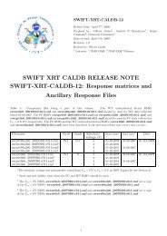
<strong>The</strong> <strong>NuSTAR</strong> <strong>Data</strong> <strong>Analysis</strong> <strong>Software</strong> <strong>Guide</strong>If the parameter 'phaparfile' is set to 'NONE', the 9 values are provided in input to the task through thespecific parameter 'timerise' (default=0.0016).4. Common mode correction, i.e. computation of 'PHAS' (9 dimensional vector):4a) exclusion of the M pixels located out of the detector or falling on bad/hot pixels4b) selection of the N pixels ("E+") with TRPHAS >= 'EVTTHR[9]' (not including the M pixelsdefined in point 4a)4c) selection of the 9-N-M pixels ("E-") with TRPHAS < 'EVTTHR[9]'<strong>The</strong> 9 values of EVTTHR[9] are read by default from the input PHAPAR file and are dependent on:- the coordinates (RAWX, RAWY) of the pixels (3X3 array)- the detector (DET_ID column)If the parameter 'phaparfile' is set to 'NONE', the 9 values are provided in input to the task throughthe specific parameter 'evtthr' (default=55).4d) calculation of the mean of the pixels with TRPHAS < 'EVTTHR[9]':< E- >=(&sum E-)/(9-N-M)4e) computation of PHAS (9 dim. vector) for the N pixels "E+":PHAS[9] = TRPHAS[9] - < E->4f) computation of PHAS (9 dim. vector) for the 9-N-M pixels "E-":PHAS[9] = TRPHAS[9]4g) setting to zero PHAS values for the M pixels out of detector:PHAS[9] = 05. computation of 'SWTRIG' column (9 dimensional vector):SWTRIG[9] = 1 for pixels with TRPHAS >= 'EVTTHR[9]'SWTRIG[9] = 0 for pixels with TRPHAS < 'EVTTHR[9]'In the second step, the task reconstructs the event charge splitting topology and assigns to them a gradefollowing a charge pattern definition stored in the input CALDB file 'gradefile' (see Figure 2). <strong>The</strong> values ofthe event grades are written in the 'GRADE' column of the output event file.Usage Examples:1. Calculate PHAS and GRADE values for the event file 'nu10012001002A_uf.evt'. <strong>The</strong> values of theevent software threshold, the time of rise correction coefficients, the capacitor offset values and theGRADE classification are read from the specific CALDB files. <strong>The</strong> results are written in the outputevent file 'nu10012001002A_out.evt'.> nucalcpha infile=nu10012001002A_uf.evt outfile=nu10012001002A_out.evt<strong>NuSTAR</strong> <strong>Software</strong> <strong>Guide</strong> 23
<strong>The</strong> <strong>NuSTAR</strong> <strong>Data</strong> <strong>Analysis</strong> <strong>Software</strong> <strong>Guide</strong>Figure 2: Definition of the <strong>NuSTAR</strong> event grades<strong>NuSTAR</strong> <strong>Software</strong> <strong>Guide</strong> 24
<strong>The</strong> <strong>NuSTAR</strong> <strong>Data</strong> <strong>Analysis</strong> <strong>Software</strong> <strong>Guide</strong>3.7 Gain Correction ('nucalcpi')<strong>The</strong> <strong>NuSTAR</strong>DAS software module 'nucalcpi' processes the <strong>NuSTAR</strong> event files to convert the chargeassociated to each event from electronic units (“Pulse Height Amplitude”, PHAS) into physical energy units(“Pulse Invariant”, PI) by applying gain corrections.<strong>The</strong> task requires in input the following files:• Level 1/1a Event File (infile)• Instrument Housekeeping File (hkfile)• CALDB Gain File (gainfile)• CALDB Charge Loss Correction File (clcfile)• CALDB Charge Loss Correction Filter File (clcfilterfile)<strong>The</strong> files generated in output by the task are:• Calibrated Level 1a Event File (outfile)<strong>The</strong> 'nucalcpi' task applies a conversion between signal charge and photon energy, which is pixel, gradeand temperature dependent. In addition, a temporal evolution of the gain is also included. Specifically, thetask reads, for each event, the ‘PHAS’ column of the input event file and the temperature associated toeach event from the input Housekeeping file. Moreover, its position on the detector ('RAWX', 'RAWY'columns) and its grade ('GRADE' column) are read.Next, by using the gain values stored in the CALDB gain file (parameter 'gainfile'), the task calculates theenergy in physical units and stores the values in a new column (named ‘PI’) of the output event file. Also,specific charge-loss corrections for multiple pixels events are applied using information from the two inputCALDB files 'clcfile' and 'clcfilterfile'.<strong>The</strong> task also computes the PI values for the 3x3 array pixels below the software threshold and stores theresult in the 'SURRPI 'column.<strong>The</strong> gain coefficient values have been evaluated from ground calibration data at three fixed temperaturesof the detector and may be periodically updated using the results of the flight calibration data analysis. <strong>The</strong>charge loss correction is applied to events with grades 1-8 using the information stored in the input CALDBCharge Loss Correction and Charge Loss Correction Filter files.<strong>The</strong> PI calculation is the result of an interpolation on temperature and on time. First, for each event the tworows valid for the epochs closest to the time of the event are chosen. <strong>The</strong>n for each row, given thetemperature associate to the event, the task performs a temperature interpolation of the gain coefficientsbetween the two nearest temperatures, thus obtaining two sets of coefficients for two contiguous times.Finally, a second interpolation with respect to time between these two sets of coefficients is performed.<strong>The</strong> temperature of each event is read from the input Housekeeping file (input parameter 'hkfile').Optionally, by setting 'hkfile' to 'NONE', the temperature associated to all the events is read from the inputparameter 'temperature'.<strong>The</strong> unit of the 'PI' and 'SURRPI' columns is set to 40 eV per channel.Usage Examples:1. Calculate PI values for the input event file 'nu10012001002A_uf.evt'. <strong>The</strong> detector temperatureassociated to each event is read from the input file 'nu10012001002A.hk'. <strong>The</strong> results are written in theoutput event file 'nu10012001002A_out.evt'.> nucalcpi infile=nu10012001002A_uf.evt outfile=nu10012001002A_out.evthkfile=nu10012001002A_fpm.hk<strong>NuSTAR</strong> <strong>Software</strong> <strong>Guide</strong> 25
<strong>The</strong> <strong>NuSTAR</strong> <strong>Data</strong> <strong>Analysis</strong> <strong>Software</strong> <strong>Guide</strong>3.8 Events Flagging ('nuflagevt')<strong>The</strong> <strong>NuSTAR</strong>DAS software module 'nuflagevt' flags the events of <strong>NuSTAR</strong> event files according to variousconditions.<strong>The</strong> task requires in input the following files:• Level 1/1a Event File (infile)• CALDB Depth Cut File (depthcutfile)• CALDB Event Cut File (eventcutfile)<strong>The</strong> files generated in output by the task are:• Calibrated Level 1a Event File (outfile)<strong>The</strong> 'nuflagevt' task first flags the events on the basis of their depth of interaction in the detectors,accounting for the total absorption probability in CZT along the direction of the original photon. <strong>The</strong> aim isto flag the internal detector background events thus improving the S/N.<strong>The</strong> depth cut profiles are read from the input CALDB file 'depthcutfile' which stores, for each pixel of thedetectors, three energy depth cut channels 'E1', 'E2' and 'E3' as a function of the event energy. For eachevent, 'nuflagevt' selects the CALDB 'E1', 'E2' and 'E3' values corresponding to its position on the detectorand energy ('RAWX', 'RAWY' and 'PI' columns on the input event file) and flags it according to the followingcriteria:• SURRPI ≤ E1 (if E2,E3 > 0)• E2 < SURRPI ≤ E1 (if E2,E3 < 0)• SURRPI ≤ E3 (if E2,E3 < 0)where 'SURRPI' is a column read from the input event file and stores the sum of the energies of theuntriggered surrounding pixels, i.e. the pixels in the 3x3 array which are below the software threshold.Next, the task flags events according to the values of the 'PRIOR', 'RESET', 'PREPHAS[5]', and 'PI'columns of the input event file. Specifically, "baseline", "prior/reset", "prior", "reset" and "energy" cuts areapplied using specific conditions on the values of these columns as detailed below:1. "Baseline cut":• (BASELINE < BASELINE1 and PI < PI_BASELINE) or (BASELINE > BASELINE2)2. "Prior/reset cut" (FPMA only):• (PRIOR2 < PRIOR < PRIOR3 and PI < PI_PRIOR) or• (RESET2 < RESET < RESET3 and PI1_RESET < PI < PI2_RESET)3. "Prior cut":• PRIOR < PRIOR14. "Reset cut":• RESET < RESET15. "Energy cut":• PI < 0 or PI > 4095where the threshold values BASELINE1, PI_BASELINE, BASELINE2, PRIOR1, PRIOR2, PRIOR3,PI_PRIOR, RESET1, RESET2, RESET3, PI1_RESET, PI2_RESET are read from the input CALDB file'evtcutfile'.<strong>NuSTAR</strong> <strong>Software</strong> <strong>Guide</strong> 26
<strong>The</strong> <strong>NuSTAR</strong> <strong>Data</strong> <strong>Analysis</strong> <strong>Software</strong> <strong>Guide</strong>As in the case of the 'nuflagbad' module, the task updates the 'STATUS' column of the event file. <strong>The</strong>values of the 'STATUS' column used by 'nuflagevt' are the following:• b0000000010000000 Event fails depth cut• b0000000100000000 Event fails baseline cut• b0000001000000000 Event fails prior/reset cut• b0000010000000000 Event fails prior cut• b0000100000000000 Event fails reset cut• b0001000000000000 Event with PI out of rangeUsage Examples:1. Flag events in the <strong>NuSTAR</strong> event file named nu10012001002A_uf.evt. <strong>The</strong> 'STATUS' column of theoutput event file 'nu10012001002A_out.evt' is updated accordingly.> nuflagevt infile=nu10012001002A_uf.evt outfile=nu10012001002A_out.evt3.9 Coordinates Transformation ('nucoord')<strong>The</strong> <strong>NuSTAR</strong>DAS software module 'nucoord' converts the coordinates of each event from the telemetryraw sub-detector (hybrid) values into celestial sky coordinates using information from the Mast AspectSolution File and the Spacecraft Attitude File.<strong>The</strong> following four coordinates systems are defined (event files columns names are indicated inparenthesis):• (RAWX, RAWY): telemetry sub-detector (hybrid) coordinates (pixel size = 12.3’’)• (DET1X, DET1Y): Focal Plane Bench Frame (FB) detector coordinates (pixel size = 2.46’’)• (DET2X, DET2Y): Optics Bench Frame (OB) detector coordinates (pixel size = 2.46’’)• (X, Y): Celestial Sky Coordinates (pixel size = 2.46’’)<strong>The</strong> 'nucoord' task also calculates, as a function of time, the sky positions of the telescope optical axis, ofthe aperture stop center and of a reference pixel of the detector.<strong>The</strong> task requires in input the following files:• Level 1/1a Event File (infile)• Mast Aspect Solution File (mastaspectfile)• Spacecraft Attitude File (attfile)• CALDB Pixel Location File (pixposfile)• CALDB Spacecraft Alignment File (alignfile)• CALDB Telescope Definition File (teldef)<strong>The</strong> files generated in output by the task are:• Calibrated Level 1a Event File (outfile)• Optical Axis File (optaxisfile)• DET1 Reference Pixel File (det1reffile)<strong>The</strong> 'nucoord' module is a script that runs in sequence the software modules 'nucalcpos', 'coordinator' and'nuskypos'. <strong>The</strong>se modules are discussed in the following sub-sections.<strong>NuSTAR</strong> <strong>Software</strong> <strong>Guide</strong> 27
<strong>The</strong> <strong>NuSTAR</strong> <strong>Data</strong> <strong>Analysis</strong> <strong>Software</strong> <strong>Guide</strong>3.9.1 Detector Coordinates Calculation ('nucalcpos')<strong>The</strong> first module run by 'nucoord' is the 'nucalcpos' task to calculate the detector coordinates in thedetectors Focal Plane Bench Frame ('DET1') and in the Optics Bench Frame ('DET2') starting from thetelemetry sub-detector coordinates ('RAW' system).<strong>The</strong> task requires in input the following files:• Level 1/1a Event File (infile)• Mast Aspect Solution File (mastaspectfile)• CALDB Pixel Location File (pixposfile)• CALDB Spacecraft Alignment File (alignfile)<strong>The</strong> files generated in output by the task are:• Calibrated Level 1a Event File (outfile)<strong>The</strong> 'nucalcpos' task reads the ‘RAWX’ and ‘RAWY’ columns of the input event file storing the originaltelemetry coordinates of the events for each of the four focal plane module sub-detectors ('DET0', 'DET1','DET2' and 'DET3'). For each sub-detector, the range of the 'RAWX' and 'RAWY' columns is 0-31.As a first step, the task transforms the RAW coordinates of the four sub-detectors in a new commoncoordinate system referred to the detectors Focal Plane Bench Frame (FB). This first step includes achange of the pixel size (by a factor of 1/5) and a correction of the detector pixels positions using theinformation from the input CALDB pixel location file (parameter 'pixposfile').<strong>The</strong> new coordinates values are saved in two new columns (‘DET1X’ and ‘DET1Y’) of the output event file.<strong>The</strong> DET1 pixel size is 12.3/5=2.46 arc seconds and the column range is 1-360. <strong>The</strong> coordinatestransformation between the 'RAW' and the 'DET1' system is illustrated in Figure 3.Figure 3: Relationship between the raw telemetry coordinates of the four sub-detectors(coordinates 'RAWX', 'RAWY') and the Focal Plane Bench Frame (coordinates 'DET1X', 'DET1Y').<strong>NuSTAR</strong> <strong>Software</strong> <strong>Guide</strong> 28
<strong>The</strong> <strong>NuSTAR</strong> <strong>Data</strong> <strong>Analysis</strong> <strong>Software</strong> <strong>Guide</strong>Next, the task uses the time dependent roto-translations stored in the Mast Aspect Solution file to calculatethe detector coordinates in the Optics Bench Frame (OB). <strong>The</strong>se coordinates are written in two newcolumns (‘DET2X’ and ‘DET2Y’) of the output event file.This transformation enables the correction of coordinates for the movement of the deployed mastconnecting the detectors Focal Plane Bench to the Optics Bench. <strong>The</strong> coordinates transformation betweenthe 'DET1' and the 'DET2' systems is illustrated in Figure 4.<strong>The</strong> DET2 pixel size is the same as the DET1 system size (2.46 arc seconds) while the column range is 1-600. Additional details on the algorithm can be found in the help file of the task.Figure 4: Relationship between the detector coordinates in the Focal Plane Bench frame (columns'DET1X','DET1Y') and in the Optics Bench frame (columns 'DET2X', 'DET2Y').3.9.2 Sky Coordinates Calculation ('coordinator')<strong>The</strong> second module run by 'nucoord' is the 'coordinator' FTOOL. This is a multi-mission tool distributed bythe <strong>HEASARC</strong> as part of the HEASoft package. For <strong>NuSTAR</strong> it is used to convert the 'DET2' coordinates in'SKY' celestial coordinates taking into account the spacecraft attitude information.<strong>The</strong> task requires in input the following files:• Level 1/1a Event File (eventfile)• Spacecraft Attitude File (attfile)• CALDB Telescope Definition File (teldef)<strong>The</strong> SKY celestial coordinates are stored in two new columns (‘X’ and ‘Y’) of the event file. <strong>The</strong> 'X' and 'Y'column range is 1-1000.<strong>NuSTAR</strong> <strong>Software</strong> <strong>Guide</strong> 29
<strong>The</strong> <strong>NuSTAR</strong> <strong>Data</strong> <strong>Analysis</strong> <strong>Software</strong> <strong>Guide</strong>3.9.3 Optical Axis, Aperture Stop Center and Detector Reference Pixel Sky Positions ('nuskypos')<strong>The</strong> third module run by 'nucoord' is the <strong>NuSTAR</strong>DAS task 'nuskypos' that calculates, as a function of time,the sky positions of the telescope optical axis, of the aperture stop center and of a reference pixel of thedetector in the DET1 coordinate system.<strong>The</strong> task requires in input the following files:• Mast Aspect Solution File (mastaspectfile)• Spacecraft Attitude File (attfile)• CALDB Spacecraft Alignment File (alignfile)• CALDB Telescope Definition File (teldef)<strong>The</strong> files generated in output by the task are:• Optical Axis File (optaxisfile)• DET1 Reference Pixel File (det1reffile)As a first step, the 'nuskypos' task reads the position of the optical axis in the DET2 frame from the inputCALDB spacecraft align file (parameter 'alignfile') and transforms it in the SKY frame. This allows themotion of the optical axis to be tracked in the SKY coordinate system and it is used to calculate the off-axisangle of a given celestial source by the 'numkarf' task during the Stage 3. <strong>The</strong> SKY position of the opticalaxis as a function of time is stored in the output file 'optaxisfile'.<strong>The</strong> 'nuskypos' module also calculates the DET2 and SKY coordinates of the center of the aperture stop.<strong>The</strong> location of the aperture stop center in the DET1 frame is stored in the CALDB 'alignfile'. <strong>The</strong> task firstreads this position and converts the Focal Plane Bench Frame (DET1) coordinates into the Optics BenchFrame (DET2) detector coordinates using the mast aspect solution file (parameter 'mastaspectfile').Afterward, the DET2 coordinates are transformed in SKY coordinates using the input spacecraft attitudeand teldef files. <strong>The</strong> DET2 and SKY positions of the aperture stop center are stored in the output file'optaxisfile'.Finally, 'nuskypos' calculates, as a function of time, the SKY coordinates of a reference pixel in the DET1frame using information from the mast aspect solution file and the spacecraft attitude file. This informationis used by the 'nuexpomap' task to generate the exposure maps. <strong>The</strong> SKY position of the detectorreference point as a function of time is stored in the output file 'det1reffile'. Additional details about thealgorithm can be found in the help file of the task.Usage Examples:1. Convert the RAW coordinates of the input event file 'nu10012001002A_uf.evt' to DET1 and DET2coordinates using the pixel location file stored in the CALDB. <strong>The</strong> DET1X/DET1Y and DET2X/DET2Ycoordinates are written in the output file 'nu10012001002A_out.evt'.> nucalcpos infile=nu10012001002A_uf.evt outfile=nu10012001002A_out.evtmastaspectfile=nu10012001002_mast.fits2. Calculate the SKY positions of the optical axis file and of the (350,350) DET1 reference pixel and storethem in the output files 'nu10012001002A_oa.fits', 'nu10012001002A_det1.fits', respectively.> nuskypos mastaspectfile=nu10012001002_mast.fits instrument=FPMAattfile=nu10012001002_att.fits pntra=258.3014 pntdec=-23.7678alignfile=nuCalign20100101v007.fits teldef=nuA20100101v002.teldefoptaxisfile=nu10012001002A_oa.fits det1reffile=nu10012001002A_det1.fits<strong>NuSTAR</strong> <strong>Software</strong> <strong>Guide</strong> 30
<strong>The</strong> <strong>NuSTAR</strong> <strong>Data</strong> <strong>Analysis</strong> <strong>Software</strong> <strong>Guide</strong>3. Convert the RAW coordinates of the input event file 'nu10012001002A_uf.evt' to DET1, DET2 and SKYcoordinates using the pixel location file stored in the CALDB. <strong>The</strong> DET1X/DET1Y, DET2X/DET2Y andX/Y coordinates are written in the output file 'nu10012001002A_out.evt'. <strong>The</strong> optical axis file and theDET1 reference file are also generated.> nucoord infile=nu10012001002A_uf.evt outfile=nu10012001002A_out.evtmastaspectfile=nu10012001002_mast.fits attfile=nu10012001002_att.fitspntra=258.3014 pntdec=-23.7678 optaxisfile=nu10012001002A_oa.fitsdet1reffile=nu10012001002A_det1.fits<strong>NuSTAR</strong> <strong>Software</strong> <strong>Guide</strong> 31
<strong>The</strong> <strong>NuSTAR</strong> <strong>Data</strong> <strong>Analysis</strong> <strong>Software</strong> <strong>Guide</strong><strong>NuSTAR</strong> <strong>Software</strong> <strong>Guide</strong> 32
<strong>The</strong> <strong>NuSTAR</strong> <strong>Data</strong> <strong>Analysis</strong> <strong>Software</strong> <strong>Guide</strong>4 EVENTS SCREENING AND EXPOSURE MAPS GENERATION (STAGE 2)This chapter describes the Stage 2 of the <strong>NuSTAR</strong> data reduction devoted to the screening of event filesby applying cleaning criteria on specified attitude/orbital/instrument parameters and event properties. Stage2 also includes the generation of sky exposure maps.<strong>The</strong> inputs of the screening stage are the Level 1a calibrated event files. Stage 2 produces in output theLevel 2 calibrated and cleaned event files to be used for scientific analysis. In the following the Stage 2<strong>NuSTAR</strong> software modules are presented in the same order used for the standard data processing alongwith software usage examples. <strong>The</strong>se processing steps are coded in the second stage of the 'nupipeline'script and cases of how to run the pipeline are illustrated in the next section.<strong>The</strong> list of the Stage 2 software modules is the following:• nucalcsaa – Calculation of the SAA passages• nufilter - Filter file generation.• nuscreen - Good Time Intervals generation and event file screening.• nulivetime - Event files dead time correction.• nuexpomap - Sky exposure maps generation.• nuskytodet – Calculation of the DET1 and DET2 coordinates from SKY coordinates.4.1 Standard <strong>Data</strong> Processing with 'nupipeline' (Stages 1 and 2)<strong>The</strong> data reduction steps described in this chapter are coded in the 'nupipeline' script. <strong>The</strong> majority of theinput parameters of the single software modules can also be set directly running the 'nupipeline' andappropriate default values have been set for most of them.By setting the input parameter 'exitstage=2' (default value), the 'nupipeline' script allows calibration (stage1) and screening (stage 2) of the data using a single command line. Both data from the FPMA and theFPMB modules are processed by default. <strong>The</strong> standard command to be used is:> nupipeline indir=/archive/10012001002/ steminputs=nu10012001002outdir=./pipeline_outNote that in this command line it is not necessary to specify 'exitstage=2' since '2' is the default value ofthis parameter. All the 'nupipeline' output files are generated in a directory named "pipeline_out".To generate also the sky exposure maps the input parameter 'createexpomap' must be set to 'yes' (defaultvalue is 'no') as illustrated in the following command line:> nupipeline indir=/archive/10012001002/ steminputs=nu10012001002outdir=./pipeline_out createexpomap=yes<strong>NuSTAR</strong> <strong>Software</strong> <strong>Guide</strong> 33
<strong>The</strong> <strong>NuSTAR</strong> <strong>Data</strong> <strong>Analysis</strong> <strong>Software</strong> <strong>Guide</strong>4.2 Rationale<strong>The</strong> calibrated Level 1a event files can include "bad" events and/or "bad" time intervals that need to beexcluded before the files can be used for the scientific data analysis. This chapter lists the criteria and themethods that are used to screen the data.<strong>The</strong> <strong>NuSTAR</strong> Calibration Team has defined the standard screening criteria used to produce the cleanedLevel 2 event files (see Section 4.7). Starting from the Level 2 files, high-level scientific products (skyimages, light-curves and energy spectra) can be extracted. We will see that it is also possible to apply adifferent data screening which may be more or less conservative than the standard one.4.3 SAA passages calculation ('nucalcsaa')<strong>The</strong> <strong>NuSTAR</strong>DAS software module 'nucalcsaa' calculates South Atlantic Anomaly (SAA) passages of the<strong>NuSTAR</strong> observatory.<strong>The</strong> task requires in input the following files:• Housekeeping file (hkfile)• Level 1a event file (evtfile)• Orbit file (orbitfile)• SAA parameter file (saaparfile)<strong>The</strong> file generated in output by the task is:• Housekeeping file (outfile)<strong>The</strong> 'nucalcsaa' module identifies the SAA passage in two different modes: 'STRICT' and 'OPTIMIZED'.<strong>The</strong> mode to be used can be set through the input parameter 'saamode'. In the 'STRICT' removal mode theSAA passages are identified by monitoring the level of the high-gain shield singles rates stored in the'SHLDHI' column of the input housekeeping file. In the 'OPTIMIZED' mode the SAA passages found in the'STRICT' mode are refined by requiring the presence of an increase of the detector events count ratessimultaneous to the observed shield singles rates increase. <strong>The</strong> results are written in a new column named'SW_SAA' of the output housekeeping file.In addition, by setting the input parameter 'tentacle' to 'yes', the task allows identification and flagging oftime intervals in which the detector events count rates show an increase. This search is done only whenthe spacecraft is entering into the SAA region and a simultaneous shield singles rates increase is notrequired. <strong>The</strong> results are written in a new column named 'SW_TENTACLE' of the output housekeeping file.<strong>The</strong> various numerical values used by the algorithm are stored in a specific CALDB file provided in inputthrough the parameter 'saaparfile'.<strong>The</strong> algorithm has been tested for steady sources with fluxes not dominating over the detector background.<strong>The</strong> 'tentacle' option should be used only when the background count rate is not stable and shows timeintervals of increased intensity. <strong>The</strong> users should carefully check the time intervals identified by the task.Usage example:1. Calculate the 'SW_SAA' column using the 'OPTIMIZED' SAA removal function. <strong>The</strong> new column isstored in the ouput file 'nu10012001002A_fpm_out.hk':> nucalcsaa hkfile=nu10012001002A_fpm.hk orbitfile=nu10012001002_orb.fitsevtfile=nu10012001002A_uf.evt outfile=nu10012001002A_fpm_out.hksaamode=OPTIMIZED tentacle=no<strong>NuSTAR</strong> <strong>Software</strong> <strong>Guide</strong> 34
<strong>The</strong> <strong>NuSTAR</strong> <strong>Data</strong> <strong>Analysis</strong> <strong>Software</strong> <strong>Guide</strong>4.4 Filter File Generation ('nufilter')<strong>The</strong> <strong>NuSTAR</strong>DAS software module 'nufilter' creates a filter file, which is used for the data screening by the'nuscreen' module (see next section 4.5). <strong>The</strong> filter file contains the attitude and orbit derived quantities, theinstrument housekeeping parameter values, and the quality of the reconstructed mast position as afunction of time.<strong>The</strong> task requires in input the following files:• Housekeeping file (hkfile)• CEB Housekeeping (cebhkfile)• Attitude file (attfile)• Position Sensing Detector file (psdcorfile)• Orbit file (orbitfile)• Makefilter configuration file (mkfconfigfile)• NORAD Two Line Elements (TLEs) file (tlefile)• Telescope definition file (teldef)• 'Prefilter' configuration file (preconfigfile)• Leap seconds file (leapfile)• AtFunction rigidity file (rigfile)<strong>The</strong> file generated in output by the task is:• Filter file (mkffile)• Attitude-orbit file (attorbfile)In the first step, 'nufilter' derives attitude and orbit related quantities by running the multi-mission 'prefilter'FTOOL. <strong>The</strong> satellite attitude information included in the attitude file is interpolated and the NORAD TwoLine Elements (TLEs) are propagated to determine satellite ephemeris quantities. This information is usedto calculate quantities such as Elevation Angle, Bright Earth Angle, Sun Angle, Cut-off rigidity, etc. <strong>The</strong>output file of 'prefilter' (parameter 'attorbfile') contains the set of columns defined in the CALDB file'preconfigfile'.In the second main step, the 'nufilter' creates the filter file by running the multi-mission FTOOL 'makefilter'.<strong>The</strong> housekeeping information is read from the input orbit file (parameter 'orbitfile'), the housekeeping files(parameters 'hkfile' and 'cebhkfile') and the spacecraft attitude file (parameter 'attfile'). <strong>The</strong> quality of thereconstructed mast position is read from the 'METGRID_FLAG' column of the position sensing detector file(parameter 'psdcorfile'). <strong>The</strong> 'makefilter' configuration file, provided in input through the parameter'mkfconfigfile', is a FITS file (by default read from the CALDB) which contains for each parameter thefollowing information: the parameter name, the name of the FITS file, the name of the extension containingthe parameter, the interpolation method, the calibration method, the output parameter name and commentsfor the corresponding keyword in the output filter file.<strong>The</strong> interpolation method is used when the value of a specific parameter is not present at given times; thecalibration method is applied when some simple numerical manipulations on the input HK parameters isneeded. Currently, the default of the interpolation method is set to copy the last known value of thatparameter. <strong>The</strong> calibration method has not been implemented yet. See also the 'makefilter' help file forfurther details.<strong>NuSTAR</strong> <strong>Software</strong> <strong>Guide</strong> 35
<strong>The</strong> <strong>NuSTAR</strong> <strong>Data</strong> <strong>Analysis</strong> <strong>Software</strong> <strong>Guide</strong>Usage example:1. Create the output 'prefilter' file named nu10012001002A.attorb and a filter file namednu10012001002A.mkf in the output directory 'pipeline_out':> nufilter hkfile=nu10012001002A_fpm.hk attfile=nu10012001002_att.fitsorbitfile=nu10012001002_orb.fits cebhkfile=nu10012001002A_ceb.hkpsdcorfile=nu10012001002A_psdcorr.fits outdir=./pipeline_out pntra=258.3014pntdec=-23.7678 tlefile=NUSTAR_TLE_ARCHIVE.txt.20130424.5 Good Time Intervals Generation and <strong>Data</strong> Screening ('nuscreen')<strong>The</strong> <strong>NuSTAR</strong>DAS software module 'nuscreen' filters calibrated event files by applying cleaning criteria onspecified orbital, attitude and instrument parameters. To this end, specific Good Time Intervals files (GTIs)based on attitude/orbit and instrument housekeeping parameters are generated from the filter file. A datascreening based on event properties (e.g. the charge pattern) is also applied to produce the output Level 1cleaned science event files.<strong>The</strong> task requires in input the following files:• Level 1 event file (infile)• Filter file (mkffile)• Housekeeping Range file (hkrangefile)• Events Range file (evtrangefile)• Housekeeping file (hkfile)• User GTI file (usrgtifile)<strong>The</strong> files generated in output by the task are:• Level 2 science event file (outfile)• Good Time Interval file (gtifile)<strong>The</strong> 'nuscreen' task i) generates a GTI file based on attitude and/or instrument housekeeping parametersand quality of the reconstructed mast position, ii) screens the data using these GTIs, iii) screens eventsusing a GRADE filter and/or a selection on the STATUS column, iv) applies the dead time correction to thetemporal keywords of the screened event files.<strong>The</strong> GTIs are calculated considering two different sets of parameters, one related to the satellite attitudeand orbit ('createattgti=yes') and the other related to instrument housekeeping ('createinstrgti=yes'). <strong>The</strong>GTI file is created by running the multi-mission FTOOL 'maketime' and contains the time intervals whereevents are considered good for science data analysis.Setting the input parameter 'gtiexpr' to 'DEFAULT' and 'hkrangefile' to 'CALDB', the attitude and instrumenthousekeeping parameters screening expressions are built using the standard criteria contained in theHousekeeping Calibration files, which are dependent on the observing mode selection provided in inputthrough the parameter 'obsmode'. <strong>The</strong> supported observing modes are SCIENCE, OCCULTATION, SLEW,SAA, CALIBRATION and SCIENCE_SC (see Section 2.1). It is possible to supply attitude and/orinstrument non-standard criteria through the parameter 'gtiexpr' providing a specific Boolean expression.<strong>The</strong> calculated GTIs are used to screen the events by setting the parameter 'gtiscreen' to 'yes' (defaultvalue). An additional user created GTI file can also be provided in input by using the 'usrgtifile' parameter.'nuscreen' filters out the events previously flagged as "bad" in the 'STATUS' column of the event file (i.e.bad/hot pixels). Moreover, the task applies a grade selection by setting the 'evtscreen' parameter to 'yes'.<strong>The</strong> standard screening criteria for GRADE and STATUS are defined in the Event Range Calibration fileand to use these the parameter 'evtrangefile' is set to CALDB and 'gradeexpr' and 'statusexpr' parameters<strong>NuSTAR</strong> <strong>Software</strong> <strong>Guide</strong> 36
<strong>The</strong> <strong>NuSTAR</strong> <strong>Data</strong> <strong>Analysis</strong> <strong>Software</strong> <strong>Guide</strong>are set to 'DEFAULT'. Non-standard screening criteria can be specified using the parameters 'gradeexpr'and 'statusexpr'. <strong>The</strong> first is for the selection on the GRADE column and values can be input as a range ora single number (e.g. 'gradeexpr=0-4' to select GRADE range between 0 and 4; 'gradeexpr=0' to selectonly GRADE equal to 0). <strong>The</strong>se inputs are used with the 'filter grade' command in 'xelect'. <strong>The</strong> second isfor the selection on the STATUS column and the value should be input as a Boolean expression, e.g.expr="STATUS==b0" to select only good events (see Sections 3.4, 3.5 and 3.8 for the definition of thevalues in the STATUS column).For the SCIENCE observing mode ('obsmode=SCIENCE'), in the case of the parameter'gtiexpr=DEFAULT', the task also calculates exposure time (not livetime corrected) during which themetrology laser spots are out of the calibrated PSD grid. <strong>The</strong> value of the exposure time is printed in theprocessing log of the task as follows: "Info: Metrology laser spots out of calibrated PSD grid for ONTIME=Xseconds". During these time intervals, in the case of a standard metrology data processing ('nupipeline'input parameter 'psdcal=yes'), the events are filtered out by 'nuscreen'. A procedure to recover this lostexposure time is given in Chapter 6.<strong>The</strong> parameters 'gtiexpr' and 'statusexpr' accept the expression directly from the command line or writteninto a text file and input by preceding the filename with '@' (e.g. statusexpr=@file.txt). <strong>The</strong> expression inthe file can be arbitrarily complex and can extend over multiple lines of the file. Lines that begin with 2slash characters (//) are ignored and can be used to add comments.If all the screening parameters are set to 'yes', the output events file contains only good events and the GTIextension is updated.'nuscreen' also applies the dead time correction to the temporal keywords of the output screened eventfiles by running the 'nulivetime' task (see Section 4.6).Usage Example:1. Generate the cleaned event file nu10012001002A01_cl.evt (DEFAULT name) and the GTI FITS filenu10012001002A01_gti.fits (DEFAULT name) using the screening expression to create the GTI writtenin the Housekeeping Range Calibration file and the events selection criteria defined in the EventsRange Calibration file:> nuscreen obsmode=SCIENCE infile=nu10012001002A_uf.evt gtiscreen=yesevtscreen=yes gtiexpr=DEFAULT gradeexpr=DEFAULT statusexpr=DEFAULTcreateattgti=yes createinstrgti=yes outdir=./pipeline_outhkfile=nu10012001002A_fpm.hk mkffile=nu10012001002A.mkf outfile=DEFAULT4.6 Dead Time Correction ('nulivetime')<strong>The</strong> <strong>NuSTAR</strong>DAS software module 'nulivetime' calculates the dead time corrections necessary to updatethe temporal keywords of the screened <strong>NuSTAR</strong> event files. It is run automatically by the 'nuscreen' task(see previous section).<strong>The</strong> task requires in input the following files:• Level 2 event file (infile)• Housekeeping file (hkfile)<strong>The</strong> file generated in output by the task is:• Level 2 event file with updated temporal keywords (outfile)'nulivetime' applies the dead time corrections and updates the temporal keywords of the screened <strong>NuSTAR</strong>event files. <strong>The</strong> dead time correction is calculated using information stored in the input file 'hkfile' and<strong>NuSTAR</strong> <strong>Software</strong> <strong>Guide</strong> 37
<strong>The</strong> <strong>NuSTAR</strong> <strong>Data</strong> <strong>Analysis</strong> <strong>Software</strong> <strong>Guide</strong>written in the keyword 'DEADC' of the output event file. 'nulivetime' also updates the 'EXPOSURE' and'LIVETIME' keywords of the output event file.Usage example:1. Apply dead time corrections to the input cleaned event file 'nu10012001002A01_cl.evt'.> nulivetime infile=nu10012001002A01_cl.evt hkfile=nu10012001002A_fpm.hkoutfile=NONE4.7 Screening criteriaIn this section we describe the screening criteria associated with i) attitude, orbital and/or instrumentalparameters, ii) quality of the reconstructed mast position and iii) specific events properties which areapplied by the 'nuscreen' module to produce Level 2 cleaned event files.<strong>The</strong> values of the attitude, orbital and instrumental parameters and the parameter related to the quality ofthe reconstructed mast position (see next sections), as a function of time are included in the Filter File(*.mkf) and are used to generate Good Time Intervals (GTIs) for which their values are within specifiedranges.4.7.1 Screening Criteria associated with the attitude and orbital parametersOne set of screening criteria is obtained by considering parameters related to the satellite position and thetelescopes boresight direction. <strong>The</strong>se parameters are part of the standard screening in 'nuscreen' (and inthe 'nupipeline' script). Non standard screening expressions can be set through the parameter 'gtiexpr'(see examples in Section 4.8). <strong>The</strong> Filter File columns that can be used for the GTIs generation are:• SAA_A, SAA_B: South Atlantic Anomaly (for focal plane module A and B, respectively) flags withvalue '0' (observatory outside the SAA) or '1' (observatory in the SAA);• SW_SAA, SW_TENTACLE: refined South Atlantic Anomaly flags as evaluated by the 'nucalcsaa'module (see Section 4.3), with value '0' (observatory outside the SAA) or '1' (observatory in theSAA);• ELV: elevation angle between the telescopes boresight and the Earth limb (degrees);• OCCULTED: flag with value '0' (Earth not in the FOV) or '1' (EARTH in the FOV);• SLEW: flag with value '0' (observatory not slewing) or '1' (observatory performing a slew betweentwo targets);• SOURCE: indicates the origin for the reconstruction of the attitude file ('1' = attitude from the startracker on the Optics Bench "CHU4", used for scientific analysis; '2' = attitude from spacecraft startrackers "CHU123");• RESIDUAL: quality of the attitude reconstruction from the "CHU4" star tracker on the OpticsBench.4.7.2 Screening Criteria associated with the mast positionFor the <strong>NuSTAR</strong> observatory, a good reconstructed mast position is crucial to evaluate accurate skycoordinates for each event. <strong>The</strong> Position Sensing Detectors (PSDs) are two optical detectors located in thefocal plane to monitor and evaluate the mast position as a function of the time. <strong>The</strong> PSDs are calibrated<strong>NuSTAR</strong> <strong>Software</strong> <strong>Guide</strong> 38
<strong>The</strong> <strong>NuSTAR</strong> <strong>Data</strong> <strong>Analysis</strong> <strong>Software</strong> <strong>Guide</strong>only in a specific grid, which is stored in the CALDB metrology grid file. Occasionally, due the mastmovements, the laser spots can be outside this calibrated grid and in this case the sky coordinates are notcalculated. As a consequence, the corresponding time intervals must be excluded from the GTIs. A specificcolumn computed by the 'numetrology' task, named 'METGRID_FLAG', of the Filter File providesinformation on the metrology grid data. This column is used for the GTIs generation and its values aredefined as follows:• METGRID_FLAG: the value of this parameter is '0' (laser spots within the calibrated grid), '1' (laserspots out of the calibrated grid) or '2' (PSD X/Y coordinates not linearized)4.7.3 Screening Criteria associated with the instrumental parametersScreening on specific instrument parameters is done to ensure that data are always included within certainspecific ranges. <strong>The</strong> 'nuscreen' software module can handle screening criteria to define GTIs according tospecific instrumental housekeeping parameter range values. <strong>The</strong> instrumental parameters and theoptimized range of the Filter File instrumental columns used for the GTIs generation are:• CAL0STAT: flag with value '0' (on-board calibration sources not in FPMA FOV) or '1' (on-boardcalibration sources in FPMA FOV);• CAL1STAT: flag with value '0' (on-board calibration sources not in FPMB FOV) or '1' (on-boardcalibration sources in FPMB FOV);• LIVETIME: exposure corrected for the dead time.4.7.4 Standard Screening Expressions for attitude/orbital/instrumental parameters<strong>The</strong> unfiltered <strong>NuSTAR</strong> Level 1a science event files can be divided in up to six different Level 2 cleanedevent files, according to the standard screening on the values of attitude/orbital/instrumental parameters.Each cleaned event file stores the data taken in one of the supported observational modes (see alsoSection 2.1) as detailed below:1. SCIENCE (01): data from the science target with good attitude reconstruction. <strong>The</strong> following screeningexpressions are used:• ELV>3 && SAA_A=0 && SAA_B=0 && SW_SAA=0 && SW_TENTACLE=0 && SLEW=0 &&SOURCE=1 && RESIDUAL0 &&(METGRID_FLAG=0||METGRID_FLAG=2) (for FPMA)• ELV>3 && SAA_A=0 && SAA_B=0 && SW_SAA=0 && SW_TENTACLE=0 && SLEW=0 &&SOURCE=1 && RESIDUAL0 &&(METGRID_FLAG=0||METGRID_FLAG=2) (for FPMB)2. OCCULTATION (02): data during the Earth occultation. <strong>The</strong> following screening expressions are used:• ELV0 && (METGRID_FLAG=0||METGRID_FLAG=2) (for FPMA)• ELV0 && (METGRID_FLAG=0||METGRID_FLAG=2)(for FPMB)<strong>NuSTAR</strong> <strong>Software</strong> <strong>Guide</strong> 39
<strong>The</strong> <strong>NuSTAR</strong> <strong>Data</strong> <strong>Analysis</strong> <strong>Software</strong> <strong>Guide</strong>3. SLEW (03): data taken during a spacecraft slew. <strong>The</strong> following screening expressions are used:• SAA_A=0 && SAA_B=0 && SW_SAA=0 && SW_TENTACLE=0 && SLEW=1 && CAL0STAT=0 &&LIVETIME>0 && (METGRID_FLAG=0||METGRID_FLAG=2) (for FPMA)• SAA_A=0 && SAA_B=0 && SW_SAA=0 && SW_TENTACLE=0 && SLEW=1 && CAL1STAT=0 &&LIVETIME>0 && (METGRID_FLAG=0||METGRID_FLAG=2) (for FPMB)4. SAA (04): data taken during a SAA passage. <strong>The</strong> following screening expression is used:• (SAA_A=1||SAA_B=1||SW_SAA=1||SW_TENTACLE=1) && (LIVETIME=0 &&(METGRID_FLAG=0||METGRID_FLAG=2)) (for FPMA and FPMB)5. CALIBRATION (05): data when the on-board calibration source is in the Field Of View. <strong>The</strong> followingscreening expressions are used:• SAA_A=0 && SAA_B=0 && SW_SAA=0 && SW_TENTACLE=0 && CAL0STAT=1 && LIVETIME>0&& (METGRID_FLAG=0||METGRID_FLAG=2) (for FPMA)• SAA_A=0 && SAA_B=0 && SW_SAA=0 && SW_TENTACLE=0 && CAL1STAT=1 && LIVETIME>0&& (METGRID_FLAG=0||METGRID_FLAG=2) (for FPMB)6. SCIENCE_SC (06): data from the science target with poor attitude reconstruction. <strong>The</strong> followingscreening expressions are used:• ELV>3 && SAA_A=0 && SAA_B=0 && SW_SAA=0 && SW_TENTACLE=0 && SLEW=0 &&SOURCE=2 && CAL0STAT=0 && LIVETIME>0 && (METGRID_FLAG=0||METGRID_FLAG=2) (forFPMA)• ELV>3 && SAA_A=0 && SAA_B=0 && SW_SAA=0 && SW_TENTACLE=0 && SLEW=0 &&SOURCE=2 && CAL1STAT=0 && LIVETIME>0 && (METGRID_FLAG=0||METGRID_FLAG=2) (forFPMB)4.7.5 Screening Criteria associated with the event proprietiesDuring data screening additional selections, associated with characteristics of the events themselves, areapplied.<strong>The</strong> current <strong>NuSTAR</strong> screening criteria are:• Removal of events on bad and hot/flickering pixels ('nuflagbad' and 'nuhotpix', see Sections 3.4and 3.5)• Removal of events failing the depth of interaction cut (see 'nuflagevt', see Section 3.8)• Removal of events failing the 'baseline', 'prior' and 'reset' cuts (see 'nuflagevt' see Section 3.8)• Removal of events with PI values out of range ('nuflagevt', see Section 3.8)• Grade selection ('nucalcpha', see Section 3.6)<strong>The</strong>se criteria are applied to the data using the information stored in the 'STATUS' column of the eventfile storing the type of flag according to the following definitions:• b0000000000000000 Good event• b0000000000000001 Event falls in a bad pixel from on-ground CALDB Bad Pixel File• b0000000000000010 Event falls in a bad pixel from on-board disabled pixel<strong>NuSTAR</strong> <strong>Software</strong> <strong>Guide</strong> 40
<strong>The</strong> <strong>NuSTAR</strong> <strong>Data</strong> <strong>Analysis</strong> <strong>Software</strong> <strong>Guide</strong>• b0000000000000100 Event falls in a bad pixel from user bad pixel file• b0000000000001000 Event has a neighbor bad from bad/disabled/user pixel list• b0000000000010000 Event falls in a detector edge pixel• b0000000000100000 Event falls in a hot/flickering pixel• b0000000001000000 Event has a neighbor hot/flickering pixel• b0000000010000000 Event fails depth cut• b0000000100000000 Event fails baseline cut• b0000001000000000 Event fails prior/reset cut• b0000010000000000 Event fails prior cut• b0000100000000000 Event fails reset cut• b0001000000000000 Event with PI out of range<strong>The</strong> standard expression used to filter out for bad events is:STATUS = b000000000x0xx000This expression excludes from the event file all the flagged events, except i) events having a neighbor badfrom bad/disabled/user pixel list, ii) events falling in a detector edge pixel and iii) events having a neighborhot/flickering pixel.In addition to the selection on the 'STATUS' column, the events are filtered according to the value of the'GRADE' column. A single X-ray event can in fact be spread in more than one detector pixel (up to 4contiguous pixels). <strong>The</strong> grade is a classification of the shape of X-ray events on the detector. <strong>The</strong> singlepixel events (i.e. grade 0) have better spectral resolution than others. Single or double pixel events aremore likely to be X-ray events than three-four pixel events. <strong>The</strong>re are 32 grades defined for <strong>NuSTAR</strong> (asdescribed in Chapter 3) and their values are stored in the 'GRADE' column of the event file.<strong>The</strong> standard grade selection defined by the <strong>NuSTAR</strong> Calibration Team and stored in the CALDB is:GRADE ≥ 0 && GRADE ≤ 26.4.7.6 SCIENCE observational mode: summary.<strong>The</strong> observing mode "SCIENCE" (01) is the mode used for the extraction of high-level scientific products.<strong>The</strong> standard screening criteria used to generate cleaned Level 2 "01" event files in the archive for thisobserving mode is summarized below:1. Removal of the following time intervals:• During a slew of the satellite;• When the Earth is in the Field Of View;• When the satellite is in the South Atlantic Anomaly;• When the angle between telescope boresight and Earth limb is equal or less than 3 deg;• When the on-board calibration source is in the Field Of View;• When the attitude reconstruction is not derived from the star tracker mounted on the OpticsBench;• When the quality of the attitude reconstruction from the star tracker on the Optics Bench is low(RESIDUAL > 7);• When either of the laser spots tracking the mast motion are outside the PSD calibrated grid;• When the LIVETIME is zero.2. Removal of bad pixels (dead, hot and flickering), events failing the depth/baseline/prior/reset cuts,events with PI channels out of range.3. <strong>The</strong> grade of the event in the range 0-26.<strong>NuSTAR</strong> <strong>Software</strong> <strong>Guide</strong> 41
<strong>The</strong> <strong>NuSTAR</strong> <strong>Data</strong> <strong>Analysis</strong> <strong>Software</strong> <strong>Guide</strong>4.8 Examples of how to screen the data with custom selections<strong>The</strong> following two equivalent methods allow performing customized screening:1. By running the 'nuscreen' module (see Section 4.5) specifying screening criteria via the inputparameters 'gtiexpr ', 'gradeexpr', and 'statusexpr'.2. By running the Stage 2 of the 'nupipeline' script. Within 'nupipeline', the screening criteria arespecified by the values of the input parameters 'gradeexpr', 'statusexpr' and 'gtiexpr01', 'gtiexpr02','gtiexpr03', 'gtiexpr04', 'gtiexpr05', 'gtiexpr06'. Note that by default (parameter 'obsmode=ALL') the'nupipeline' runs the 'nuscreen' module six times.4.8.1 Example of how to use 'nuscreen'For detailed spectral analysis it could be necessary to optimize the energy resolution. To this aim, userscan decide to select only events with grades equal to '0' (single pixel events) starting from the Level 2event file. <strong>The</strong> command line to be used is:> nuscreen infile=nu10012001002A01_cl.evt gtiscreen=no evtscreen=yesgtiexpr=NONE gradeexpr=0 statusexpr=NONE outdir=./hkfile=nu10012001002A_fpm.hk outfile=nu10012001002A01_cl_grade0.evtIn this example the GTIs are not applied, by setting the 'gtiscreen' parameter to 'no', since the input eventfile was already cleaned. <strong>The</strong> grade selection is done setting the parameter 'evtscreen' to yes. <strong>The</strong>parameter 'gradeexpr' specifies the values to filter in the column 'GRADE'.4.8.2 Example of how to use nupipeline<strong>The</strong> above example above can also be handled by 'nupipeline'. In this case both Stage 1 and Stage 2 areexecuted and the command to be used is:> nupipeline indir=./10012001002 outdir=./pipeline_out steminputs=nu10012001002obsmode=SCIENCE instrument=FPMA evtscreen=yes gradeexpr=04.9 Generation of Exposure Maps ('nuexpomap')<strong>The</strong> <strong>NuSTAR</strong>DAS software module 'nuexpomap' generates Sky Exposure Maps storing, for a givenobservation, the net exposure time for each sky pixel. <strong>The</strong> exposure map accounts for detector bad and hotpixels, detector gaps, attitude variations, mast movements and, optionally, telescope vignetting.<strong>The</strong> task requires in input the following files:• Level 2 event file (infile)• Attitude file (attfile)• Mast Aspect Solution file (mastaspectfile)• DET1 Reference Point file (det1reffile)• Pixel Location File (pixposfile)<strong>NuSTAR</strong> <strong>Software</strong> <strong>Guide</strong> 42
<strong>The</strong> <strong>NuSTAR</strong> <strong>Data</strong> <strong>Analysis</strong> <strong>Software</strong> <strong>Guide</strong>• Alignment File (alignfile)• Telescope Definition File (teldef)• Instrument Probability Map File (instrprobmapfile)• Vignetting File (vignfile)<strong>The</strong> file generated in output by the task is:• Exposure Map file (expomapfile)<strong>The</strong> NUSTARDAS 'nuexpomap' task first generates a set of instrument maps in Focal Plane Bench DET1frame where bad/hot pixels and detector gaps are marked using information from the 'BADPIX' extensionof the input event file (parameter 'infile') and from the input CALDB Instrument Probability Map File(parameter 'instrprobmapfile'), respectively.<strong>The</strong> set of DET1 instrument maps is constructed as follows. First, the task reads the input file 'det1reffile'storing the X/Y SKY position as a function of time of a reference pixel in the DET1 coordinate system.Second, the X/Y offsets relative to their minimum value in the 'det1reffile' are calculated. Third, the X/Yoffsets are binned with a bin size in pixels specified by the input parameter 'pixbin'. Each bin defines a timeinterval during which the spatial fluctuations due to attitude variations and mast movements are below the'pixbin' value and are considered constant. This information is then used by 'nuexpomap' to build theaspect histogram defining, for each spatial offset bin, the time interval and duration of each single DET1instrument map. By setting the parameters 'offsetfile' and 'aspecthistofile' to something other then 'NONE'the task saves in the current directory the spatial offset and aspect histogram files, respectively.Each DET1 instrument map is then transformed to the Optics Bench DET2 frame using the mast aspectsolution (parameter 'mastaspectfile') and the CALDB align file (parameter 'alignfile'). In this step,'nuexpomap' makes use of the multi-mission FTOOLs 'combinexform' and 'imagetrans'.Optionally, if the parameter 'vignflag' is set to 'yes', the task applies the vignetting correction to the DET2instrument maps using the vignetting CALDB file (parameter 'vignfile'). <strong>The</strong> vignetting correction is appliedat the energy value specified by the parameter 'energy'.Next, the DET2 instrument maps are transformed to the SKY frame using the attitude information providedin input through the parameter 'attfile'. To this end, the multi-mission FTOOLs 'getxform', 'imagetrans' and'getwcs' are used by 'nuexpomap'. <strong>The</strong> total exposure map, storing in each pixel the net exposure time ofthe observation, is then calculated by summing the single exposure maps in sky coordinates. Dead timecorrections are included in the total exposure map.By setting the parameters 'det1instrfile','det2instrfile' and 'skyinstrfile' to something other then 'NONE' thetask saves in the current directory the single DET1, DET2 and SKY instrument maps as FITS IMAGEextensions in the corresponding output files.Optionally, the task allows the generation of smaller exposure maps covering a user defined region of theSKY grid, as defined by the input parameters 'skyx', 'skyy' and 'skysize'. In this case 'nuexpomap' uses thetask ‘nuskytodet’ to transform 'skyx' and 'skyy' in the DET1 and DET2 coordinates, needed to generate theexposure maps.<strong>The</strong> 'nuexpomap' task can also be executed starting from an input DET2 instrument map produced in aprevious run, allowing to skip the first processing steps. In this case the DET2 instrument map should befull size (1000x1000 pixels) and not corrected for vignetting. <strong>The</strong> user should provide the input DET2 mapthrough the parameter 'indet2instrfile'.<strong>NuSTAR</strong> <strong>Software</strong> <strong>Guide</strong> 43
<strong>The</strong> <strong>NuSTAR</strong> <strong>Data</strong> <strong>Analysis</strong> <strong>Software</strong> <strong>Guide</strong>Usage Examples:1. Generate the exposure map nu10012001002A01_ex10.img including the vignetting correction atenergy 10 keV (default), starting from the Level 2 event file nu10012001002A01_cl.evt. <strong>The</strong> commandline to be used is:> nuexpomap infile=nu10012001002A01_cl.evt attfile=nu10012001002_att.fitsmastaspectfile=nu10012001002_mast.fits det1reffile=nu10012001002A_det1.fitsexpomapfile=nu10012001002_ex10.img2. Same as above, but providing in input a DET2 instrument map (not corrected for vignetting):> nuexpomap infile=nu10012001002A01_cl.evt attfile=nu10012001002_att.fitsindet2instrfile=nu40060001001A01_det2.fitsexpomapfile=nu10012001002_ex10.img3. <strong>The</strong> vignetting correction can be applied to the exposure maps at an energy different from the defaultvalue, by setting the value of the parameter 'energy'. In the example below the energy used for thevignetting correction is 30 keV.> nuexpomap infile=nu10012001002A01_cl.evt attfile=nu10012001002_att.fitsmastaspectfile=nu10012001002_mast.fits det1reffile=nu10012001002A_det1.fitsexpomapfile=nu10012001002_ex30.img energy=304. <strong>The</strong> exposure map can be also generated without applying the vignetting correction, starting from theLevel 2 event file nu10012001002A01_cl.evt. In this case the command line to be used is:> nuexpomap infile=nu10012001002A01_cl.evt attfile=nu10012001002_att.fitsmastaspectfile=nu10012001002_mast.fits det1reffile=nu10012001002A_det1.fitsexpomapfile=nu10012001002_ex_no_vig.img vignflag=no4.9.1 Exposure maps generation in 'nupipeline'<strong>The</strong> exposure map for the '01' observation mode (i.e. "SCIENCE") can be directly generated when runningthe 'nupipeline' script by setting the parameter 'createexpomap' to 'yes' (default value is 'no'), as illustratedin the following examples.Usage examples:1. <strong>The</strong> results of 'nuexpomap' in Example 1 of section 4.9, can be reproduced by running 'nupipeline' asfollows:> nupipeline indir=./10012001002 outdir=./pipeline_out steminputs=nu10012001002obsmode=SCIENCE instrument=FPMA createexpomap=yes<strong>NuSTAR</strong> <strong>Software</strong> <strong>Guide</strong> 44
<strong>The</strong> <strong>NuSTAR</strong> <strong>Data</strong> <strong>Analysis</strong> <strong>Software</strong> <strong>Guide</strong>2. <strong>The</strong> results of 'nuexpomap' in Example 3 of section 4.9, can be reproduced by running 'nupipeline' asfollows:> nupipeline indir=./10012001002 outdir=./pipeline_out steminputs=nu10012001002obsmode=SCIENCE instrument=FPMA createexpomap=yes energy=303. <strong>The</strong> results of 'nuexpomap' in Example 4 of Section 4.9, can be reproduced by running 'nupipeline' asfollows:> nupipeline indir=./10012001002 outdir=./pipeline_out steminputs=nu10012001002obsmode=SCIENCE instrument=FPMA createexpomap=yes expovignflag=no4.10 Trasformation of SKY coordinates in DET1 and DET2 coordinates ('nuskytodet')<strong>The</strong> NUSTARDAS 'nuskytodet' calculates as a function of time the Focal Plane Bench Frame coordinates(DET1) and the Optics Bench Frame coordinates (DET2) of an input position in SKY coordinates.<strong>The</strong> task requires in input the following files:• Attitude file (attfile)• Mast Aspect Solution file (mastapectfile)• Alignment file (alignfile)• Telescope definition file (teldef)<strong>The</strong> file generated in output by the task is:• SKY Reference Pixel File in DET1 and DET2 system (skydetfile)'nuskytodet' reads the input SKY coordinates from the parameters 'skyxref' and 'skyyref'. <strong>The</strong>tranformations from SKY to DET1 and DET2 frames are calculated using information from the attitude file('attfile'), the mast aspect solution file ('mastaspectfile') and the two CALDB files 'teldef' and 'align'. <strong>The</strong>DET1 and DET2 values as a function of time are stored in the output file 'skydetfile'.Usage Examples:1. Calculate the DET1 and DET2 coordinates of the SKY pixel (X,Y)=(500,500) and store them in theoutput file 'nu10012001002A_skydet.fits'.> nuskytodet instrument=FPMA mastaspectfile=nu10012001002_mast.fitsattfile=nu10012001002_att.fits pntra=258.3014 pntdec=-23.7678skydetfile=nu10012001002A_skydet.fits<strong>NuSTAR</strong> <strong>Software</strong> <strong>Guide</strong> 45
<strong>The</strong> <strong>NuSTAR</strong> <strong>Data</strong> <strong>Analysis</strong> <strong>Software</strong> <strong>Guide</strong><strong>NuSTAR</strong> <strong>Software</strong> <strong>Guide</strong> 46
<strong>The</strong> <strong>NuSTAR</strong> <strong>Data</strong> <strong>Analysis</strong> <strong>Software</strong> <strong>Guide</strong>5 EXTRACTION OF PRODUCTS (STAGE 3)This chapter describes Stage 3 of the <strong>NuSTAR</strong> data reduction, which is dedicated to the generation ofhigh-level scientific products (light-curves, energy spectra, sky images, ARF and RMF files).<strong>The</strong> inputs to Stage 3 are the Level 2 cleaned and calibrated event files and other files generated duringthe previous processing stages. Stage 3 produces in output the Level 3 data products to be used forscientific analysis.In the following sections the Stage 3 <strong>NuSTAR</strong> software modules are presented in the same order used forthe standard data processing along with software usage examples. <strong>The</strong>se processing steps are coded in adedicated module named 'nuproducts' which constitutes the third stage of the 'nupipeline' script.Examples of how to execute Stage 3 automatically for standard data processing are illustrated in the nexttwo sections.<strong>The</strong> list of the Stage 3 software modules is the following:• nuproducts - Extract high-level data products from a Level 2 event file• nubackscale - Apply backscale correction to energy spectra (called by 'nuproducts')• nulccorr - Apply livetime, PSF/EXPOSURE and vignetting corrections to light-curves (called by'nuproducts')• numkarf - Generates an ARF file for an input PHA file (called by 'nuproducts')• numkrmf - Generates an RMF file for an input spatial region file (called by 'nuproducts')<strong>The</strong> following Level 3 data products are generated during this stage:• Source energy spectrum• Background energy spectrum• Redistribution Matrix File (RMF)• Ancillary Response File (ARF)• Source light-curve• Background light-curve• Field image in sky coordinates<strong>The</strong> level 3 <strong>NuSTAR</strong> files are FTOOLS compliant and users can perform spectral analysis by using theXSPEC package and temporal analysis with the LCURVE or XRONOS software packages (seehttp://heasarc.gsfc.nasa.gov/docs/xanadu/xanadu.html).Note that the 'nuproducts' module makes use of the XSELECT multi-mission software package to extractenergy spectra and light-curves. <strong>The</strong> module also applies to them <strong>NuSTAR</strong> specific corrections (e.g.livetime and PSF corrections). It is therefore strongly suggested that energy spectra and light-curvesare extracted using the 'nuproducts' module and not separately using directly the XSELECTpackage.<strong>NuSTAR</strong> <strong>Software</strong> <strong>Guide</strong> 47
<strong>The</strong> <strong>NuSTAR</strong> <strong>Data</strong> <strong>Analysis</strong> <strong>Software</strong> <strong>Guide</strong>5.1 Standard <strong>Data</strong> Processing with 'nuproducts' (Stage 3)To apply the data reduction steps for the extraction of high-level scientific products the 'nupipeline' taskmakes use of a dedicated module named 'nuproducts' (see Section 5.3). <strong>The</strong> 'nuproducts' taskautomatically retrieves all the necessary input files from a directory specified by the input parameter 'indir'which must be set to the output directory of a previous run of 'nupipeline' (Stages 1 and 2). An example ofa standard command line for a point-like source is:> nuproducts indir=./pipeline_out instrument=FPMB steminputs=nu10012001002outdir=./products srcregionfile=source.reg bkgregionfile=background.regIn this case 'nuproducts' is run from the same directory used to execute the 'nupipeline' run (pipeline_out inthe various command line examples) and generates in the 'products' directory the source energy spectrum,background energy spectrum, RMF file, ARF file, corrected source light-curve, corrected background lightcurve,and field image in sky coordinates for the FPMB module. <strong>The</strong> source and background extractionregions are read from the input ASCII files 'source.reg' and 'background.reg', respectively. <strong>The</strong>se filesshould have a format compatible with XSELECT and DS9.Optionally, by setting the input parameter 'rungrppha=yes', the 'nuproducts' module generates in outputalso a grouped source energy spectrum (parameter 'grpphafile'). This is achieved through an internal run ofthe FTOOL 'grppha'. <strong>The</strong> energy spectrum is grouped such that a minimum of 'grpmincounts' counts iscontained in each bin and the energy channels lower than 'grppibadlow' and higher than 'grppibadhigh' areflagged as bad. In the following the command line to be used to generate a source grouped energyspectrum is shown:> nuproducts indir=./pipeline_out instrument=FPMB steminputs=nu10012001002outdir=./products srcregionfile=source.reg bkgregionfile=background.regrungrppha=yes grpmincounts=30 grppibadlow=35 grppibadhigh=1909<strong>The</strong> above example generates a binned energy spectrum (named 'nu10012001002B01_sr_grp.pha') with aminimum of 30 counts in each new energy channel and with PI channels '0-34' and '1910-4095' flagged asbad. Note that the '35-1909' PI range corresponds to the 3-78 keV calibrated energy range.To extract the Level 3 scientific products with the 'nuproducts' module directly from the 'event_cl' archivedirectory it is also necessary to set the 'attfile' and 'hkfile' input parameters as follows:> nuproducts indir=./event_cl instrument=FPMB steminputs=nu10012001002outdir=./products srcregionfile=source.reg bkgregionfile=background.regattfile=/archive/10012001002/auxil/nu10012001002_att.fitshkfile=/archive/10012001002/hk/nu10012001002B_fpm.hk<strong>NuSTAR</strong> <strong>Software</strong> <strong>Guide</strong> 48
<strong>The</strong> <strong>NuSTAR</strong> <strong>Data</strong> <strong>Analysis</strong> <strong>Software</strong> <strong>Guide</strong>5.2 Standard <strong>Data</strong> Processing with 'nupipeline' (Stages 1, 2 and 3)<strong>The</strong> data reduction steps for the extraction of high-level scientific products are also coded in the third stageof the 'nupipeline' script which directly runs the 'nuproducts' module. This can done by setting the inputparameter ’exitstage=3’. In this case the 'nupipeline' script, in a single command line, applies to the datathe calibration steps (Stage 1), the screening steps (Stage 2) and extracts the high-level data products(Stage 3). By default, data from both modules (FPMA and FPMB) are processed.<strong>The</strong> standard command line to be used is:> nupipeline indir=/archive/10012001002/ steminputs=nu10012001002outdir=./pipeline_out exitstage=3 srcregionfile=source.regbkgregionfile=background.reg5.3 <strong>The</strong> Extraction of high-level data products ('nuproducts')<strong>The</strong> NUSTARDAS module 'nuproducts' is a perl module which utilizes the XSELECT multi-missionsoftware package to extract source and background light-curves and energy spectra from the inputcalibrated and screened event files (Level 2). By default, 'nuproducts' calls the 'numkrmf' and 'numkarf'tasks to generate the RMF and/or ARF files appropriate for the spectral analysis.<strong>The</strong> ‘nuproducts’ module also updates the values of the output source spectrum keywords 'BACKFILE','RESPFILE' and 'ANCRFILE' with the names of the background spectrum file, the RMF file and the ARFfile, respectively. For spectral analysis (e.g. by using XSPEC), users should decide on grouping or not thesource spectrum using an external tool (e.g. by using the FTOOL 'grppha'). By default, 'nuproducts' callsthe 'nulccorr' task, to apply various corrections to the output light-curves, and the 'nubackscale' task toapply backscale corrections to the output energy spectra.<strong>The</strong> input parameters needed to run 'nuproducts' are the Right Ascension and Declination of the source(i.e. parameters 'srcra' and 'srcdec'), the Right Ascension and Declination of the center of the backgroundregion (i.e. parameters 'bkgra' and 'bkgdec'), or alternatively, the source and background extraction regionfiles. Also, the data input directory, the stem for FITS input files, the chosen <strong>NuSTAR</strong> detector (FPMA orFPMB) and the output directory for the generation of the products, must be specified.<strong>The</strong> task requires in input the following files:• Level 2 event file (infile)• Source region file (srcregionfile)• Background region file (bkgregionfile)• Attitude file (attfile)• Mast Aspect Solution file (mastaspectfile)• DET1 Reference Point file (det1reffile)• Optical Axis file (optaxisfile)• User GTI file (usrgtifile)• Housekeeping file (hkfile)• Pixel location file (pixposfile)• Alignment file (alignfile)• Telescope definition file (teldef)<strong>NuSTAR</strong> <strong>Software</strong> <strong>Guide</strong> 49
<strong>The</strong> <strong>NuSTAR</strong> <strong>Data</strong> <strong>Analysis</strong> <strong>Software</strong> <strong>Guide</strong>• Instrument Probability Map File (instrprobmapfile)• 2D-PSF file for Light curve correction (psffile)• Vignetting file (vignfile)• On-axis ARF file (inarffile)• 2D-PSF Grouping File for ARF generation (grppsffile)• Aperture Stop Correction file (apstopcorrfile)• Ghost Rays Correction file (grcorrfile)• DETABS Correction file (detabscorrfile)• RMF Grouping File for RMF file generation (grprmffile)<strong>The</strong> files generated in output are the following:• Source spectrum (phafile)• Source corrected light-curve (lcfile)• Source image (imagefile)• Background spectrum (bkgphafile)• Background corrected light-curve (bkglcfile)• Response Matrix file (outrmffile)• Ancillary Response file (outarffile)<strong>The</strong> source spectrum and light-curve are extracted by filtering the data on a spatial region in SKYcoordinates. If the parameter 'srcregionfile' is set to ‘DEFAULT’ it is possible, through the parameters'srcra', 'srcdec' and 'srcradius', to specify the Right Ascension and Declination of the center and the radiusof a circular extraction region. An extraction region file with an arbitrary shape can be input through theparameter 'srcregionfile'. This file should have a format compatible with XSELECT and DS9. Note that, forpoint-like sources, while arbitrary region geometries can be used for products extraction, specific regiongeometries are required for the generation of corrected ARFs and the PSF correction of light-curves. For alist of the supported geometries of the extraction regions see the sections dedicated to the modules'numkarf' and 'nulccorr' later in this Chapter.A full field of view image in sky coordinates is produced if the parameter 'imagefile' is different from 'NONE'.Note that energy spectra and light-curves are not background subtracted at this point.By setting the parameter 'bkgextract' to 'yes' (default value) it is possible to extract the spectrum and lightcurveof the background from a region file specified by the parameter 'bkgregionfile'. Alternatively('bkgregionfile'='DEFAULT'), it is possible to define through the parameters 'bkgra', 'bkgdec', 'bkgradius1'and 'bkgradius2' the Right Ascension, Declination of the center and the inner and outer radii of an annularextraction region.If the input parameter 'runbackscale' is set to ‘yes’ (default), the 'BACKSCAL' keywords of the source andbackground energy spectra are updated by running the 'nubackscale' task (see Section 5.5).By default (parameter 'correctlc=yes'), the task applies the livetime, PSF/EXPOSURE and vignettingcorrections to the output source light-curves by running the 'nulccorr' task (see Section 5.6). In the case ofbackground light-curve only livetime and EXPOSURE corrections are applied. Note that in the case ofpoint-like sources the EXPOSURE correction is always applied to the background light-curve. In the caseof extended sources the background light-curve EXPOSURE correction is managed by the value of theinput parameter 'lcexpoflag'.<strong>NuSTAR</strong> <strong>Software</strong> <strong>Guide</strong> 50
<strong>The</strong> <strong>NuSTAR</strong> <strong>Data</strong> <strong>Analysis</strong> <strong>Software</strong> <strong>Guide</strong>For the extraction of light-curves it is possible set the binsize (in seconds) via the parameter 'binsize'. Forthe extraction of light-curves and sky images the minimum and maximum values of the PI channels can bechanged via the parameters 'pilow' and 'pihigh'. Moreover, it is possible to apply a user defined temporalfilter to the event file providing in input a FITS GTI file (parameter 'usrgtifile').By setting the parameter 'plotdevice' to GIF or PS, it is possible to choose the device for plotting thegenerated image, light curve and spectrum.Optionally, by setting the input parameters 'rummkarf' and 'runmkrmf' to ‘yes’ (default value), the task alsogenerates the ARF and RMF files appropriate for the spectral analysis of the source energy spectrum. Thisis achieved by running the tasks 'numkarf' and 'numkrmf' (see Sections 5.7 and 5.8, respectively).<strong>The</strong> task can also optionally apply the barycenter correction to the output files by setting the inputparameter 'barycorr' to 'yes' (default is 'no'). <strong>The</strong> barycenter correction is calculated through themultimission FTOOL 'barycorr'. <strong>The</strong> correction is applied to the following input files: 'infile', 'mastaspectfile','attfile', 'det1reffile', 'optaxisfile' and 'hkfile'. Note that when 'nuproducts' is run providing in input a user GTIfile (parameter 'usrgtifile') the barycenter correction is applied to it if the input parameter 'usrgtibarycorr' isset to 'yes' (default value).To apply the barycenter correction it is necessary to set the input parameter 'orbitfile' and specify theposition of the source (parameters 'srcra_barycorr' and 'srcdec_barycorr'). <strong>The</strong> barycenter correctedcleaned event file can be saved in the output directory by setting the parameter 'cleanup=no'.Optionally, by setting the input parameter 'rungrppha' to 'yes', the output source energy spectrum isgrouped through an internal run of the FTOOL 'grppha'. <strong>The</strong> energy spectrum is grouped such that aminimum of 'grpmincounts' counts is contained in each bin. Also, the energy channels lower than'grppibadlow' and higher than 'grppibadhigh' are flagged as bad.Usage examplesPoint-like source case:5.3A.Default Circular and annular extraction regions for source and background, respectively:> nuproducts indir=./pipeline_out instrument=FPMB steminputs=nu10012001002outdir=./products srcra=187.2779154 srcdec=2.0523883 bkgra=187.2779154bkgdec=2.0523883In this example nuproducts generates in the output directory the following data products:• source energy spectrum (pha file), extracted in circular region centered on srcra and srcdec withradius of 20 software pixels (parameter srcradius). <strong>The</strong> 'BACKSCAL' keyword in the sourcespectrum is updated for the exposure variations within the extraction region.• background energy spectrum (pha file), extracted in annular region centered on bkgcra and bkgdecwith inner and outer radius of 50 (parameter bkgradius1) and 80 (parameter bkgradius2) softwarepixels, respectively. <strong>The</strong> 'BACKSCAL' keyword in the background spectrum is updated for theexposure variations within the extraction region.• RMF file, appropriate for the source energy spectrum.• ARF file, appropriate for the point-like source spectrum.• Source light-curve (not background subtracted) corrected for the livetime, the PSF and vignettingcorrections, applied at energy 'lcenergy' =10 keV .<strong>NuSTAR</strong> <strong>Software</strong> <strong>Guide</strong> 51
<strong>The</strong> <strong>NuSTAR</strong> <strong>Data</strong> <strong>Analysis</strong> <strong>Software</strong> <strong>Guide</strong>• Background light-curve (corrected for the livetime and EXPOSURE corrections).• Field image in sky coordinates.5.3B. It is also possible to use source and/or background extraction region geometries different fromcircular and annular ones, respectively. In this case the region files with an arbitrary shape can be inputthrough the parameters 'srcregionfile' and/or 'bkgregionfile', respectively. However, note that the task'numkarf' supports only circular, elliptical and annular extraction regions centered on the source. <strong>The</strong>'CIRCLE-CIRCLE' region is not supported, so we suggest using the 'ANNULUS' region. Moreover'numkarf' only applies the ghost-ray correction (parameter 'grflag') for point-like sources (parameter'extended=no') and for circular extraction regions for the source:> nuproducts indir=./pipeline_out instrument=FPMB steminputs=nu10012001002outdir=./products srcregionfile=source.reg bkgregionfile=background.reglcfile=NONE bkglcfile=NONE imagefile=NONEIn this example nuproducts generates in the output directory the following data products:• source energy spectrum (pha file), extracted in the region source.reg. <strong>The</strong> 'BACKSCAL'keyword of the source spectrum is updated for the exposure variations within theextraction region.• background energy spectrum (pha file), extracted in the region background.reg. <strong>The</strong>'BACKSCAL' keyword of the background spectrum is updated for the exposure variationswithin the extraction region.• RMF file (appropriate for the source spectrum),• ARF file (for a point-like source spectrum).5.3C. It is also possible to apply a time filter to the event file and to the high-level data products byproviding an input FITS GTI (Good time interval) file (parameter 'usrgtifile'):> nuproducts indir=./pipeline_out instrument=FPMB steminputs=nu10012001002outdir=./products srcregionfile=source.reg bkgregionfile=background.regusrgtifile=myGTIs.fits5.3D. To analyze light-curves in a specific energy range and temporal bin size, it is necessary to set thevalues of the parameters ‘pilow’ and ‘pihigh’, which define the minimum and maximum value of the PIto be included in the extracted light curve, and the parameter binsize:> nuproducts indir=./pipeline_out instrument=FPMB steminputs=nu10012001002phafile=NONE outdir=./products srcregionfile=source.reg bkgextract=nobkglcfile=NONE imagefile=NONE runmkarf=no runmkrmf=no pilow=100pihigh=1000 binsize=500 lcnergy=5In this example nuproducts generates in the directory products only the source light-curve extractedusing the spatial region source.reg, the energy range 100-1000 (in PI channels) and with a temporalbin size of 500 s. <strong>The</strong> source light-curve, not background subtracted, is corrected for the livetime andthe PSF and vignetting corrections are applied at energy 5 keV.5.3E. Barycenter correction (with default circular and annular extraction regions for source andbackground, respectively):<strong>NuSTAR</strong> <strong>Software</strong> <strong>Guide</strong> 52
<strong>The</strong> <strong>NuSTAR</strong> <strong>Data</strong> <strong>Analysis</strong> <strong>Software</strong> <strong>Guide</strong>> nuproducts indir=./pipeline_out instrument=FPMB steminputs=nu10012001002outdir=./products srcra=187.2779154 srcdec=2.0523883 bkgra=187.2779154bkgdec=2.0523883 barycorr=yes srcra_barycorr=187.2779154srcdec_barycorr=2.0523883orbitfile=/archive/10012001002/auxil/nu10012001002_orb.fitsIn this example nuproducts generates in the output directory the following barycenter corrected dataproducts:• source energy spectrum (pha file), extracted in circular region centered on srcra and srcdec withradius of 20 software pixels (parameter srcradius). <strong>The</strong> 'BACKSCAL' keyword in the sourcespectrum is updated for the exposure variations within the extraction region.• background energy spectrum (pha file), extracted in annular region centered on bkgcra and bkgdecwith inner and outer radius of 50 (parameter bkgradius1) and 80 (parameter bkgradius2) softwarepixels, respectively. <strong>The</strong> 'BACKSCAL' keyword in the background spectrum is updated for theexposure variations within the extraction region.• RMF file, appropriate for the source energy spectrum.• ARF file, appropriate for the point-like source spectrum.• Source light-curve (not background subtracted) corrected for the livetime, the PSF and vignettingcorrections, applied at energy 'lcenergy' =10 keV .• Background light-curve (corrected for the livetime and EXPOSURE corrections).• Field image in sky coordinates.5.3F. Same as Example 5.3B, in addition a grouped source energy spectrum is generated (named'nu10012001002B01_sr_grp.pha'):> nuproducts indir=./pipeline_out instrument=FPMB steminputs=nu10012001002outdir=./products srcregionfile=source.reg bkgregionfile=background.reglcfile=NONE bkglcfile=NONE imagefile=NONE rungrppha=yes grpmincounts=30grppibadlow=35 grppibadhigh=1909Extended sources case.In the case of an extended source the Point Spread Function and Ghost-Rays corrections are not appliedto the output ARF file. <strong>The</strong> correction terms include the vignetting, the aperture stop, the detectorabsorption and the EXPOSURE corrections. To generate the ARF appropriate for an extended source, thevalue of the parameters 'extended' must be set to 'yes' (default value is 'no').5.3G.> nuproducts indir=./pipeline_out instrument=FPMB steminputs=nu10012001002outdir=./products srcregionfile=source.reg bkgregionfile=background.reglcfile=NONE bkglcfile=NONE imagefile=NONE extended=yesIn this example nuproducts generates in the output directory the following files:• source energy spectrum (pha file), extracted in the region source.reg. <strong>The</strong> 'BACKSCAL' keyword ofthe source spectrum is updated for the exposure variations within the extraction region.• background enegy spectrum (pha file), extracted in the region background.reg. <strong>The</strong> 'BACKSCAL'keyword of the background spectrum is updated for the exposure variations within the extractionregion.<strong>NuSTAR</strong> <strong>Software</strong> <strong>Guide</strong> 53
<strong>The</strong> <strong>NuSTAR</strong> <strong>Data</strong> <strong>Analysis</strong> <strong>Software</strong> <strong>Guide</strong>• RMF file (appropriate for the source spectrum).• ARF file (for the extended source spectrum).5.4 <strong>The</strong> Extraction of high-level data products with 'nupipeline'<strong>The</strong> 'nuproducts' module for the extraction of high-level products is coded in the third stage of the'nupipeline' script. <strong>The</strong>refore by using 'nupipeline' setting the parameter 'exitstage' to '3', the script calls'nuproducts' and extracts the high-level data products. In the examples given below the same numbering ofthe previous section is used. Note that it is not possible to generate source grouped energy spectra withthe 'nupipeline' module.Usage examples:5.4A.5.4B.5.4C.5.4D.5.4E.> nupipeline indir=./10012001002 outdir=./pipeline_outsteminputs=nu10012001002 srcra=187.2779154 srcdec=2.0523883obsmode=SCIENCE instrument=FPMB exitstage=3 bkgra=187.2779154bkgdec=2.0523883> nupipeline indir=./10012001002 outdir=./pipeline_outsteminputs=nu10012001002 obsmode=SCIENCE instrument=FPMB exitstage=3srcregionfile=source.reg bkgregionfile=background.reg fpmb_lcfile=NONEfpmb_bkglcfile=NONE fpmb_imagefile=NONE> nupipeline indir=./10012001002 outdir=./pipeline_outsteminputs=nu10012001002 obsmode=SCIENCE instrument=FPMB exitstage=3srcregionfile=source.reg bkgregionfile=background.regusrgtifile=myGTIs.fits> nupipeline indir=./10012001002 outdir=./pipeline_outsteminputs=nu10012001002 obsmode=SCIENCE instrument=FPMB exitstage=3srcregionfile=source.reg bkgextract=no fpmb_phafile=NONEfpmb_bkglcfile=NONE fpmb_imagefile=NONE runmkarf=no runmkrmf=no pilow=100pihigh=1000 binsize=500> nupipeline indir=./10012001002 outdir=./pipeline_outsteminputs=nu10012001002 srcra=187.2779154 srcdec=2.0523883obsmode=SCIENCE instrument=FPMB exitstage=3 bkgra=187.2779154bkgdec=2.0523883 barycorr=yes srcra_barycorr=187.2779154srcdec_barycorr=2.05238835.4G.(EXTENDED SOURCES):> nupipeline indir=./10012001002 outdir=./pipeline_outsteminputs=nu10012001002 obsmode=SCIENCE instrument=FPMB exitstage=3srcregionfile=source.reg bkgregionfile=background.reg fpmb_lcfile=NONEfpmb_bkglcfile=NONE fpmb_imagefile=NONE extended=yes<strong>NuSTAR</strong> <strong>Software</strong> <strong>Guide</strong> 54
<strong>The</strong> <strong>NuSTAR</strong> <strong>Data</strong> <strong>Analysis</strong> <strong>Software</strong> <strong>Guide</strong>5.5 Apply backscale correction to energy spectra ('nubackscale')<strong>The</strong> <strong>NuSTAR</strong>DAS software module 'nubackscale' generates a corrected source and/or backgroundspectrum accounting for the exposure variations within the extraction regions. <strong>The</strong> corrections arecalculated using the sky exposure map generated internally by the 'nuexpomap' task. A sky exposure map,not corrected for vignetting, can also be provided in input to the task by setting the input parameter'inexpomapfile', allowing to reduce the execution time. <strong>The</strong> task generates output FITS PHA files('srcoutfile' and/or 'bkgoutfile') with updated values of the 'BACKSCAL' keyword.<strong>The</strong> task requires in input the following files:• source spectrum PHA file (srcphafile)• background spectrum PHA file (bkgphafile)• Level 2 event file (evtfile)• Attitude file (attfile)• Mast Aspect Solution file (mastaspectfile)• DET1 Reference Point file (det1reffile)• Pixel location file (pixposfile)• Alignment file (alignfile)• Telescope definition file (teldef)• Instrument Probability Map File (instrprobmapfile)<strong>The</strong> files generated in output by the task are:• source spectrum PHA file (srcoutfile)• background spectrum PHA file (bkgoutfile)This module is called by the 'nuproducts' module.Usage example:1. In this example 'nubackscale' will update, with the backscale correction, the BACKSCAL keyword ofthe input source and background spectra: ‘nu10012001002A01_sr.pha’ and‘nu10012001002A01_bkg.pha’, respectively:> nubackscale evtfile=nu10012001002A01_cl.evtsrcphafile=nu10012001002A01_sr.pha attfile=nu10012001002_att.fitsdet1reffile=nu10012001002A_det1.fits mastaspectfile=nu10012001002_mast.fitsbkgphafile=nu10012001002A01_bkg.pha srcoutfile=NONE bkgoutfile=NONE2. Using this command line, 'nubackscale' applies the backscale correction to the input source andbackground spectra. <strong>The</strong> corrected spectra are written in the output files'nu10012001002A01_sr_corr.pha' and 'nu10012001002A01_bk_corr.pha':> nubackscale evtfile=nu10012001002A01_cl.evtsrcphafile=nu10012001002A01_sr.pha attfile=nu10012001002_att.fitsdet1reffile=nu10012001002A_det1.fits mastaspectfile=nu10012001002_mast.fits<strong>NuSTAR</strong> <strong>Software</strong> <strong>Guide</strong> 55
<strong>The</strong> <strong>NuSTAR</strong> <strong>Data</strong> <strong>Analysis</strong> <strong>Software</strong> <strong>Guide</strong>bkgphafile=nu10012001002A01_bkg.pha srcoutfile=nu10012001002A01_sr_corr.phabkgoutfile=nu10012001002A01_bkg_corr.pha3. Same as Example 1, but with a sky exposure map (not corrected for vignetting) provided in input:> nubackscale evtfile=nu10012001002A01_cl.evtsrcphafile=nu10012001002A01_sr.pha attfile=nu10012001002_att.fitsdet1reffile=nu10012001002A_det1.fits mastaspectfile=nu10012001002_mast.fitsbkgphafile=nu10012001002A01_bkg.pha srcoutfile=NONE bkgoutfile=NONEinexpomapfile=nu10012001002A01_ex.img5.6 Apply livetime, PSF/EXPOSURE and vignetting corrections to light-curves ('nulccorr')<strong>The</strong> <strong>NuSTAR</strong>DAS software module 'nulccorr' generates a corrected light-curve accounting for the livetime,the PSF/EXPOSURE and vignetting corrections. <strong>The</strong> livetime correction is always applied and it iscalculated using the values of the 'LIVETIME' column in the input file 'hkfile'.<strong>The</strong> task requires in input the following files:• Light curve file (lcfile)• Spectrum pha file (phafile)• Optical Axis File (optaxisfile)• Level 2 event file (infile)• Attitude file (attfile)• Mast Aspect Solution file (mastapectfile)• DET1 Reference Point file (det1reffile)• Instrument Housekeeping File (hkfile)• Pixel location file (pixposfile)• Alignment file (alignfile)• Telescope definition file (teldef)• Instrument Probability Map File (instrprobmapfile)• 2D-PSF file (psffile)• Vignetting file (vignfile)<strong>The</strong> file generated in output by the task is:• Corrected light curve file (outlcfile)For point-like sources (parameter 'extended=no'), the task applies to the output light-curve the PSF andvignetting corrections by setting the input parameters 'psfflag' and 'vignflag' to 'yes' (default values),respectively. <strong>The</strong> PSF term includes the corrections for the fraction of photons falling outside the light-curveextraction region and for bad pixels and detector gaps located within the extraction region. <strong>The</strong> vignettingand PSF corrections are applied using the energy value specified by the parameter 'energy'.<strong>NuSTAR</strong> <strong>Software</strong> <strong>Guide</strong> 56
<strong>The</strong> <strong>NuSTAR</strong> <strong>Data</strong> <strong>Analysis</strong> <strong>Software</strong> <strong>Guide</strong>For the point-like case, circular, elliptical and annular extraction regions centered on the source aresupported by the task if the PSF correction is applied. No restrictions on the shape of the extraction regionare present if the input parameter 'psfflag' is set to 'no'.For extended sources (parameter 'extended=yes'), the task applies to the output light-curve theEXPOSURE and vignetting corrections when setting the input parameters 'expoflag' and 'vignflag' to 'yes'(default values), respectively. <strong>The</strong> EXPOSURE correction term accounts for bad pixels and detector gapslocated within the extraction region. Also in this case, the vignetting correction is applied using the energyvalue specified by the parameter 'energy'. For the extended case there are no restrictions on the shape ofthe extraction region.By default the PSF/EXPOSURE and vignetting corrections are calculated using a sky instrument map (see'nuexpomap' ) generated internally by the task. To reduce the task execution time, it is possible to providein input to 'nulccorr' a sky instrument map file and the associated aspect histogram file through theparameters 'inskyinstrfile' and 'inaspecthistofile', respectively. Note that in the latter case to producevignetting corrected output light-curves it is necessary to provide in input a sky instrument map correctedfor vignetting.<strong>The</strong> task generates an output FITS light curve ('outlcfile') with the 'RATE' and 'ERROR' columns correctedfor the different factors. <strong>The</strong> original values of the 'RATE' and 'ERROR' columns are saved and stored inthe two new columns 'RATE_ORIG' and 'ERROR_ORIG' of the output light-curve. <strong>The</strong> task also sets thevalue of the 'DEADAPP' keyword to 'T' to reflect the fact that the output ligh-curve is livetime corrected.<strong>The</strong> task adds or updates to the output light-curve the keyword 'NULCCO' with value 'T' to specify that thelight-curve has been corrected.This module is called by the 'nuproducts' module.Usage examples:1. In this example 'nulccorr' applies the livetime, PSF and vignetting corrections at energy 10 keV to theinput light curve:> nulccorr evtfile=nu10012001002A01_cl.evt outlcfile=NONEsrcphafile=nu10012001002A01_sr.pha attfile=nu10012001002_att.fitsdet1reffile=nu10012001002A_det1.fits mastaspectfile=nu10012001002_mast.fits2. <strong>The</strong> energy of PSF and vignetting corrections can be specified by the parameter 'energy'. In the examplebelow 'nulccorr' applies the correction at an energy of 5 keV:> nulccorr evtfile=nu10012001002A01_cl.evt outlcfile=NONE energy=5srcphafile=nu10012001002A01_sr.pha attfile=nu10012001002_att.fitsdet1reffile=nu10012001002A_det1.fits mastaspectfile=nu10012001002_mast.fits3. Extended source: in this case the light-curve is corrected for the EXPOSURE variations (i.e. detectorsedges/gaps, bad/hot pixel), but no PSF correction is applied. <strong>The</strong> parameter 'extended' has to be set to'yes' for the extended case, as in the example below:> nulccorr evtfile=nu10012001002A01_cl.evt outlcfile=NONEsrcphafile=nu10012001002A01_sr.pha attfile=nu10012001002_att.fitsdet1reffile=nu10012001002A_det1.fits mastaspectfile=nu10012001002_mast.fitsextended=yes4. Background light curve: in this case the light curve should be corrected only for the livetime andEXPOSURE variations. <strong>The</strong> command line to be used for a background light-curve is:> nulccorr evtfile=nu10012001002A01_cl.evt outlcfile=NONEsrcphafile=nu10012001002A01_sr.pha attfile=nu10012001002_att.fits<strong>NuSTAR</strong> <strong>Software</strong> <strong>Guide</strong> 57
<strong>The</strong> <strong>NuSTAR</strong> <strong>Data</strong> <strong>Analysis</strong> <strong>Software</strong> <strong>Guide</strong>det1reffile=nu10012001002A_det1.fits mastaspectfile=nu10012001002_mast.fitsextended=yes vignflag=no5.7 Generation of ARF files ('numkarf')<strong>The</strong> <strong>NuSTAR</strong>DAS software module 'numkarf' generates an OGIP-style Ancillary Response File (ARF) foran input PHA file, which has been extracted by 'nuproducts' or 'nupipeline' or XSELECT.<strong>The</strong> task requires in input the following files:• Source spectrum PHA file (phafile)• Source region file (srcregionfile)• Optical Axis File (optaxisfile)• Level 2 event file (infile)• Attitude file (attfile)• Mast Aspect Solution file (mastaspectfile)• DET1 Reference Point file (det1reffile)• On-axis ARF File (inarffile)• Pixel location file (pixposfile)• Alignment file (alignfile)• Telescope definition file (teldef)• Instrument Probability Map File (instrprobmapfile)• 2D-PSF Grouping File (grppsffile)• Vignetting file (vignfile)• Aperture Stop Correction file (apstopcorrfile)• Ghost Rays Correction file (grcorrfile)• DETABS Correction file (detabscorrfile)<strong>The</strong> task generates in output the following files:• ARF file (outfile)• Off-Axis file (offaxisfile)• Off-Axis Histogram file (offaxishisto)• Aperture Stop Histogram file (apstophisto)• Ghost Rays Histogram file (grhisto)'numkarf' generates an OGIP-style Ancillary Response Function (ARF) file which is suitable for input intothe spectral fitting program XSPEC. <strong>The</strong> ARF file contains the effective area of the telescope as a functionof energy needed to perform spectral analysis. This is calculated by correcting the input CALDB ARF file,storing the effective area of a source located on-axis without Point Spread Function (PSF) losses.<strong>The</strong> input CALDB ARF file is modified taking into account the vignetting, the aperture stop, the ghost rays,the detector absorption and the PSF corrections. <strong>The</strong>se terms, which are functions of the energy, are<strong>NuSTAR</strong> <strong>Software</strong> <strong>Guide</strong> 58
<strong>The</strong> <strong>NuSTAR</strong> <strong>Data</strong> <strong>Analysis</strong> <strong>Software</strong> <strong>Guide</strong>dependent on the source off-axis angle and azimuth angle. <strong>The</strong> PSF and ghost rays corrections are alsodependent on the radius of the PHA file extraction region. <strong>The</strong> PSF correction term also includes thecorrections for the exposure map such as detector gaps and mast/attitude variations.<strong>The</strong> input files for on-axis effective area, PSF, aperture stop, ghost rays, detector absorption and vignettingare, by default, read from the Calibration <strong>Data</strong>base (CALDB). For the PSF files, the CALDB stores a set offiles which are energy dependent. <strong>The</strong> association between energy and CALDB PSF files is specified in theCALDB PSF Grouping File provided in input through the parameter 'grppsffile'.<strong>The</strong> time dependent off-axis angle, azimuth value and distance between the optical axis and the aperturestop center are calculated using the position of the telescope optical axis and of the aperture stop centerstored in the input file 'optaxisfile' (see 'nuskypos' and 'nucoord' help files), and written in the output file'offaxisfile'.<strong>The</strong> distributions of off-axis and azimuth angles for the vignetting correction are stored in the output file'offaxishisto'. <strong>The</strong> distributions of off-axis, azimuth angles and distance between the optical axis and theaperture stop center for the aperture stop and ghost rays corrections are stored in the output files'apstophisto' and 'grhisto' files, respectively.<strong>The</strong> vignetting, aperture stop, ghost rays and PSF corrections are calculated, taking into account thesource off-axis and azimuth angle distributions, by a weighted mean of the input CALDB values.If parameters 'psfflag', 'apstopflag', 'grflag', 'detabs' and 'vignflag' are set to 'yes', the PSF, the aperturestop, the ghost rays, the detector absorption and the vignetting corrections are applied to the input ARF file,respectively.<strong>The</strong> source position and the radius of the extraction region is read from the input spectrum (parameter'phafile') in the 'REG00101' extension. Only for the detector absorption correction, the source extractionregion is read from the input parameter 'srcregionfile'. Circular, elliptical and annular extraction regionscentred on the source are supported by the task. Note that the ghost rays correction is supported only forpoint-like sources (parameter 'extended=no') and for circular source extraction regions.<strong>The</strong> task can also generate the ARF file for extended sources, such as clusters of galaxies or supernovaremnants, by setting the parameter 'extended' to 'yes'. To follow the spatial variations of the detectorproperties for the extended source case, the extraction region file, read from the first extension of the inputspectrum file, is divided in boxes of size chosen by setting the parameter 'boxsize'. For each sub-region, anARF is produced with the vignetting correction, the aperture stop correction and the detector absorptioncorrection, but without including the point-like PSF correction. This set of ARF files are then combinedusing the 'addarf' FTOOL to produce the output ARF. Note that for the extended case there no restrictionson the shape of the extraction region.For extended sources, the task execution time can be reduced by providing in input a sky exposure mapfile not corrected for vignetting (parameter 'inexpomapfile').This module is called by the 'nuproducts' task.Usage examples:1. In this example numkarf generates the ARF suitable for the point-like spectrumnu10012001002A01_sr.pha extracted by using the circular region source.reg. <strong>The</strong> ARF is corrected forthe PSF, the aperture stop, the ghost rays, the detector absorption and the vignetting factors. If thesource extraction region source.reg is not circular, the ghost rays correction is not applied to the outputARF file:> numkarf infile=nu10012001002A01_cl.evt phafile=nu10012001002A01_sr.phaoutfile=nu10012001002A01_sr.arf optaxisfile=nu10012001002B_oa.fitsdet1reffile=nu10012001002B_det1.fits srcregionfile=source.regmastaspectfile=nu10012001002_mast.fits attfile=nu10012001002_att.fitsoffaxisfile=NONE offaxishisto=NONE grhisto=NONE apstophisto=NONE<strong>NuSTAR</strong> <strong>Software</strong> <strong>Guide</strong> 59
<strong>The</strong> <strong>NuSTAR</strong> <strong>Data</strong> <strong>Analysis</strong> <strong>Software</strong> <strong>Guide</strong>2. Extended source: in this case the ARF cannot be corrected for the PSF and ghost-rays, and only theaperture stop, the detector absorption and the vignetting corrections are applied. To generate the ARFappropriate for an extended source, the value of the parameter 'extended' has to be set to 'yes' .Assuming that nu10012001002A01_sr.pha is the spectrum of the extended source extracted by usingthe region file source.reg, the command line to be used is:> numkarf infile=nu10012001002A01_cl.evt srcregionfile=source.regphafile=nu10012001002A01_sr.pha outfile=nu10012001002A01_sr.arfoptaxisfile=nu10012001002B_oa.fits det1reffile=nu10012001002B_det1.fitsoffaxisfile=NONE offaxishisto=NONE grhisto=NONE apstophisto=NONEmastaspectfile=nu10012001002_mast.fits attfile=nu10012001002_att.fitsextended=yes5.8 Generation of RMF files ('numkrmf')<strong>The</strong> <strong>NuSTAR</strong>DAS software module 'numkrmf' generates an OGIP-style Response Matrix File (RMF) whichis suitable for input into the spectral fitting program XSPEC.<strong>The</strong> task requires in input the following files:• Level 2 event file (infile)• Source region file (srcregionfile)• CALDB RMF Grouping File (grprmffile)• User GTI file (usrgtifile)<strong>The</strong> file generated in output by the task is:• RMF file (outfile)For <strong>NuSTAR</strong>, the CALDB stores two sets of RMF files, to be used for event files filtered or not filtered forthe depth cut. Each set stores the RMF file appropriate for each detector pixel or group of detector pixels.<strong>The</strong> association between pixels and CALDB RMF files is specified in the CALDB RMF Grouping Fileprovided in input through the parameter 'grprmffile'.'numkrmf' first reads the keyword 'DEPTHCUT' of the input event file (see Section 3.9) to select theappropriate 'grprmffile' CALDB file. Next, for each CALDB RMF file, it computes the number of events inthe input event file ('infile') within the input spatial region file (parameter 'srcregionfile').<strong>The</strong> response of the detector is finally generated by 'numkrmf' calculating a weighted mean of the CALDBRMF files. <strong>The</strong> mean is computed using as weights the corresponding number of events and making use ofthe multi-mission FTOOL 'addrmf'. Optionally, by setting the input parameter 'cmprmf' to 'yes', the outputRMF file is compressed using the multi-mission FTOOL 'cmprmf'.This module is called by the 'nuproducts' task.Usage example:1. Generates the RMF file appropriate for the input spatial region 'source.reg':> numkrmf infile=nu10012001002A01_cl.evt srcregionfile=source.regoutfile=nu10012001002A01_sr.rmf<strong>NuSTAR</strong> <strong>Software</strong> <strong>Guide</strong> 60
<strong>The</strong> <strong>NuSTAR</strong> <strong>Data</strong> <strong>Analysis</strong> <strong>Software</strong> <strong>Guide</strong>6 SPECIFIC ANALYSIS CASESIn this Chapter we discuss some important issues dealing with the analysis of <strong>NuSTAR</strong> data. In fact,particular operative conditions during an observation may require specific procedures. Before providing therecipes to be followed by the user in such cases, a short description of a standard data processing is given.6.1 Standard Processing<strong>The</strong> first step in the data reduction of <strong>NuSTAR</strong> data is to calibrate and screen the Level 1 event files. Thiscan be achieved by running the 'nupipeline' script as illustrated in the following command line:> nupipeline indir=/archive/10012001002/ steminputs=nu10012001002outdir=./pipeline_out obsmode=SCIENCENote that only the 'SCIENCE' observing mode data, storing the data with good attitude reconstruction, areconsidered in this example. Both data from the FPMA and the FPMB modules are processed. All the'nupipeline' output files are generated in the directory named "pipeline_out". In particular the outputdirectory contains the calibrated and cleaned Level 2 event files nu10012001002A01_cl.evt andnu10012001002B01_cl.evt. Optionally, by setting the input parameter 'createexpomap=yes', the skyexposure maps are also generated.<strong>The</strong> second step in the data reduction is the extraction of high-level scientific products. To this end, the'nuproducts' module automatically retrieves all the necessary input files from the output directory of'nupipeline' (see above). An example of a standard command line for a point-like source for module FPMAis the following:> nuproducts indir=./pipeline_out instrument=FPMA steminputs=nu10012001002outdir=./products srcregionfile=source.reg bkgregionfile=background.regThis command generates in the 'products' directory the source and background energy spectra, the RMFand ARF files for spectral analysis, the corrected source and background light-curves, and a field image insky coordinates. In the case of extended sources, the option 'extended=yes' must be added to the'nuproducts' command line. <strong>The</strong> 'nuproducts' module also updates the values of the keywords 'BACKFILE','RESPFILE' and 'ANCRFILE' of the source energy spectra with the names of the background spectrum file,the RMF file and the ARF file, respectively.<strong>The</strong> source and background extraction regions are read from the input ASCII files 'source.reg' and'background.reg', respectively. <strong>The</strong>se files should have a format compatible with XSELECT and DS9. Notethat for point-like sources only circular, elliptical, and annular source extraction regions are supported by'nuproducts'. Note also that the ARF ghost rays correction, applied only for point-like sources, requires theuse of circular source extraction regions. For the extended source case there are no restrictions on theshape of the extraction region.<strong>NuSTAR</strong> <strong>Software</strong> <strong>Guide</strong> 61
<strong>The</strong> <strong>NuSTAR</strong> <strong>Data</strong> <strong>Analysis</strong> <strong>Software</strong> <strong>Guide</strong><strong>The</strong> 'nuproducts' module makes use of the XSELECT multi-mission software package to extract sourceand background light-curves and energy spectra. <strong>The</strong> module automatically calls the 'nulccorr' task, toapply livetime and PSF corrections to the output light-curves, and the 'nubackscale' task to apply backscalecorrections to the output energy spectra. For these reasons, it is strongly suggested that energyspectra and light-curves are extracted from calibrated and cleaned event files using the'nuproducts' module. It is possible to generate energy spectra and light-curves directly with theXSELECT package, however this requires a manual correction using the ‘nubackscale' and 'nulccorr'modules.To extract the Level 3 scientific products with the 'nuproducts' module directly from the 'event_cl' archivedirectory it is also necessary to set the 'attfile' and 'hkfile' input parameters as follows:> nuproducts indir=./event_cl instrument=FPMA steminputs=nu10012001002outdir=./products srcregionfile=source.reg bkgregionfile=background.regattfile=/archive/10012001002/auxil/nu10012001002_att.fitshkfile=/archive/10012001002/hk/nu10012001002A_fpm.hk6.2 Generation of high-level data products with a user defined temporal filter<strong>The</strong> 'nuproducts' module allows the user to apply a time filter to all the high-level data products generatedin output, i.e. the source and background energy spectra and light-curves, the RMF and ARF files. This isachieved by providing in input a Good Time Interval (GTI) file in FITS format through the parameter'usrgtifile'. <strong>The</strong> command line to be used is the following:> nuproducts indir=./pipeline_out instrument=FPMA steminputs=nu10012001002outdir=./products srcregionfile=source.reg bkgregionfile=background.regusrgtifile=mygti.fitsNote that in the case of a user GTI file it is not possible to generate the correct data products if these areextracted with the XSELECT package individually. To produce Level 3 data products with a userdefined temporal filter it is mandatory to use the 'nuproducts' module.6.3 Metrology data out of range: recovery of lost exposure timeAs described in Chapter 3, the first data reduction step for <strong>NuSTAR</strong> is the processing of the raw metrologydata by the 'numetrology' module. <strong>The</strong> laser metrology system on-board <strong>NuSTAR</strong> tracks the temporalchanges of the alignment of the mast connecting the Focal Plane Bench (FB) and the Optics Bench (OB)mirror system. This system makes use of two lasers, located on the OB, and two Position SensingDetectors ('PSDO' and 'PSD1') on the FB registering the positions of the laser spots (for more details seeHarrison et al. 2013, ApJ, 770, 103).<strong>The</strong> processing of the raw metrology data first calculates the raw X and Y positions of the laser spots onthe detectors 'PSD0' and 'PSD1' as a function of time. Next, the X/Y coordinates are corrected for thedistortions introduced by the response of the two laser detectors. This correction is applied only if the laserspots are inside a defined calibrated range for X and Y values. In sporadic cases the laser spots falloutside this calibrated range and the corresponding time intervals are filtered out during the data screening.<strong>NuSTAR</strong> <strong>Software</strong> <strong>Guide</strong> 62
<strong>The</strong> <strong>NuSTAR</strong> <strong>Data</strong> <strong>Analysis</strong> <strong>Software</strong> <strong>Guide</strong>For the 'SCIENCE' observing mode, the value of the exposure time (not livetime corrected) lost because ofthe laser spots outside the X/Y calibrated range is reported in a specific keyword of the cleaned Level 2event file named 'NUPSDOUT'. <strong>The</strong> value of the lost exposure time is also reported in the STDOUT of‘nupipeline’ module as in the example below:nuscreen_0.1.9: Info: Metrology laser spots out of calibrated PSDgrid for ONTIME=391.8 secondsFPMA: .... Stage II: ** WARNING Metrology laser spots out ofcalibrated PSD grid for ONTIME=391.8 seconds for Observing Mode '01'To recover the lost exposure time, at the expense of some positional uncertainty, a specific 'nupipeline'input parameter named 'psdcal' allows to use of the raw X/Y coordinates of the laser spots without applyingthe distortion correction. This procedure is safe for the analysis of bright sources, however users mustcheck the sky images to verify the accuracy of the reconstruction of celestial positions.To use raw PSD X/Y positions, and recover the exposure time, the 'nupipeline' input parameter 'psdcal'must be set to 'no' (default value is ’yes’) by the user as in the example below:> nupipeline indir=/archive/10012001002/ steminputs=nu10012001002outdir=./pipeline_out obsmode=SCIENCE psdcal=no6.4 Barycenter CorrectionThis section describes how to apply the barycenter correction to the <strong>NuSTAR</strong> data making use of the multimissionFTOOL 'barycorr', distributed as part of HEASoft software package by the <strong>NASA</strong>-<strong>HEASARC</strong>.<strong>The</strong> barycenter correction can be applied to <strong>NuSTAR</strong> data using the following two methods:1. run of the 'nuproducts' module with the input parameter 'barycorr=yes';2. run of 'barycorr' to the light-curves generated by a standard run of 'nuproducts'.Note that in both cases the 'nuproducts'/'barycorr' modules also apply <strong>NuSTAR</strong> specific clock offsetcorrections using information stored in an input file specified through the input parameter 'clockfile' (set to'CALDB' by default).6.4.1 Method 1: Level 3 files correction with 'nuproducts'<strong>The</strong> barycenter correction is applied to the output files by setting the 'nuproducts' input parameter'barycorr=yes'. <strong>The</strong> correction is applied internally running the 'barycorr' module on the following input files:'infile', 'mastaspectfile', 'attfile', 'det1reffile', 'optaxisfile' and 'hkfile'. Note that when 'nuproducts' is runproviding in input a user GTI file (parameter 'usrgtifile') the barycenter correction is applied to it if the inputparameter 'usrgtibarycorr' is set to 'yes' (default value).To apply the barycenter correction it is necessary to set the input parameter 'orbitfile' and specify theposition of the source (parameters 'srcra_barycorr' and 'srcdec_barycorr'). <strong>The</strong> barycenter correctedcleaned event file can be saved in the output directory by setting the parameter 'cleanup=no'. <strong>The</strong> examplebelow gives the command line to be used:> nuproducts indir=./pipeline_out instrument=FPMA steminputs=nu10012001002outdir=./products srcregionfile=source.reg bkgregionfile=background.regbarycorr=yes srcra_barycorr=187.2779154 srcdec_barycorr=2.0523883orbitfile=/archive/10012001002/auxil/nu10012001002_orb.fits<strong>NuSTAR</strong> <strong>Software</strong> <strong>Guide</strong> 63
<strong>The</strong> <strong>NuSTAR</strong> <strong>Data</strong> <strong>Analysis</strong> <strong>Software</strong> <strong>Guide</strong>6.4.2 Method 2: light-curve correction with 'barycorr'To apply the barycenter correction to the light-curve generated by a standard run of the 'nuproducts'module the following command lines must be executed.i. Standard 'nuproducts' run, where 'pipeline_out' is the 'nupipeline' output directory:> nuproducts indir=./pipeline_out instrument=FPMA steminputs=nu10012001002outdir=./products srcregionfile=source.reg bkgregionfile=background.regii.Barycenter correction of the output light-curve run from the 'nuproducts' output directory (named'products' in the above command line):> barycorr infile=nu10012001002A01_sr.lc outfile=nu10012001002A01_sr_corr.lcorbitfiles=/archive/auxil/nu10012001002_orb.fits ra=187.2779154 dec=2.0523883<strong>NuSTAR</strong> <strong>Software</strong> <strong>Guide</strong> 64
<strong>The</strong> <strong>NuSTAR</strong> <strong>Data</strong> <strong>Analysis</strong> <strong>Software</strong> <strong>Guide</strong>7 CALIBRATION FILES7.1 Introduction<strong>The</strong> <strong>NuSTAR</strong>DAS software interfaces with the calibration information via the Calibration <strong>Data</strong>base(CALDB) which consists of a collection of files, each dedicated to a specific aspect of calibration, organizedin a specific directory structure. <strong>Software</strong> retrieves the CALDB files by querying an index file, whichcontains records of the calibration files and their validity.<strong>The</strong> CALDB files for <strong>NuSTAR</strong> can be divided in three categories:• Files used by the software to calibrate events, for example, to calculate the PI values, or to recordstandard screening criteria.• Files used in the analysis of extracted products, for example, the response matrices.• Files not used directly by the software that contain instrument characteristics and are included inthe calibration database for archival purposes.<strong>The</strong> following sections list the <strong>NuSTAR</strong> CALDB files that are directly used by the <strong>NuSTAR</strong> software tasksand in the analysis of extracted products.<strong>The</strong> calibration files are named according to the following convention:nu[instrument][datatype][date]v[ver].[ext]where [instrument] indicates the focal plane module, [datatype] provides an identifier for the calibrationdata, [date] indicates the first date of validity of the file and [ver] is the version number for that file. E.g.nuCmetgrid20100101v001.fits.7.2 List of calibration files used by <strong>NuSTAR</strong>DAS<strong>The</strong> table in this section provides a quick reference for the calibration files required by the <strong>NuSTAR</strong>software tasks. <strong>The</strong> table contains five columns. <strong>The</strong> first lists the name of the software task; the secondgives a brief description of the calibration files used by the task; the third indicates the Focal Plane Module(‘A’ for FPMA, ‘B’ for FPMB and ‘C’ for both) for which that calibration file is applicable; the fourth containsthe [datatype] in the filename of the calibration file and/or the file extension ([ext]) if different from ’.fits’; thelast column lists the CALDB subdirectory containing the file.<strong>Software</strong> Calibration File Description [FPM] [datatype] directoryTask/[ext]numetrology Metrology Grid C metgrid /fpm/bcf/metrology/Alignment C align /fpm/bcf/align/nuattcorr CHUs Quaternion Offset C chuoffset /fpm/bcf/instrument/nuflagbad Ground Bad Pixel A,B badpix /fpm/bcf/badpix/nuhotpix - - - -nucalcpha Capacitors offset A,B offset /fpm/bcf/cap_offset/Event Grade C grade /fpm/bcf/grade/Energy Calibration Coefficients A,B phapar /fpm/bcf/instrument/nucalcpi Gain coefficients A,B gain /fpm/bcf/gain/Charge Loss Coefficients A,B clc /fpm/bcf/clc/Fluorescence photons energy boundaries C clcfilter /fpm/bcf/clc/nuflagevt Depth Cut Coefficients A,B depthcut /fpm/bcf/instrument/Event Cut Coefficients A,B evtcut /fpm/bcf/instrument/nucoord Pixel Position Coefficients A,B pixpos /fpm/bcf/pixpos/Alignment C align /fpm/bcf/align/Telescope definition A,B teldef /fpm/bcf/teldef/nucalcpos Pixel Position Coefficients A,B pixpos /fpm/bcf/pixpos/<strong>NuSTAR</strong> <strong>Software</strong> <strong>Guide</strong> 65
<strong>The</strong> <strong>NuSTAR</strong> <strong>Data</strong> <strong>Analysis</strong> <strong>Software</strong> <strong>Guide</strong>Alignment C align /fpm/bcf/align/nuskypos Alignment C align /fpm/bcf/align/Telescope definition A,B teldef /fpm/bcf/teldef/nucalcsaa SAA Parameters C saapar /fpm/bcf/instrument/nufilter makefilter parameters C mkconf /fpm/bcf/instrument/prefilter parameters C preconf /fpm/bcf/instrument/Telescope definition A,B teldef /fpm/bcf/teldef/nuscreen Housekeeping range valuesA,B hkrange0n /fpm/bcf/instrument/Modes n = 1 to 6GRADE and STATUS range values A,B evtrange /fpm/bcf/instrument/nulivetime - - - -nuexpomap Pixel Position Coefficients A,B pixpos /fpm/bcf/pixpos/Alignment C align /fpm/bcf/align/Telescope definition A,B teldef /fpm/bcf/teldef/DET1 Instrument Probability Map A,B instrprobmap /fpm/bcf/instrmap/Vignetting A,B vign /fpm/bcf/vign/nuskytodet Alignment C align /fpm/bcf/align/Telescope definition A,B teldef /fpm/bcf/teldef/nuproducts Pixel Position Coefficients A,B pixpos /fpm/bcf/pixpos/Alignment C align /fpm/bcf/align/Telescope definition A,B teldef /fpm/bcf/teldef/DET1 Instrument Probability Map A,B instrprobmap /fpm/bcf/instrmap/Ancillary Response A,B arf /fpm/bcf/arf/Raytrace 2D PSF A,B 2dpsfen /fpm/bcf/psf/2D PSF files grouping A,B grppsf /fpm/bcf/psf/Vignetting A,B vign /fpm/bcf/vign/Aperture Stop ARF Correction A,B apstop /fpm/bcf/aperture_stop/Ghost Rays ARF Correction A,B gr /fpm/bcf/ghost_rays/Detector Absorption Coefficients A,B detabs /fpm/bcf/detabs/RMF files grouping A,B grprmf /fpm/bcf/rmf/nulccorr Pixel Position Coefficients A,B pixpos /fpm/bcf/pixpos/Alignment C align /fpm/bcf/align/Telescope definition A,B teldef /fpm/bcf/teldef/DET1 Instrument Probability Map A,B instrprobmap /fpm/bcf/instrmap/Raytrace 2D PSF A,B 2dpsfen /fpm/bcf/psf/Vignetting A,B vign /fpm/bcf/vign/nubackscale Pixel Position Coefficients A,B pixpos /fpm/bcf/pixpos/Alignment C align /fpm/bcf/align/Telescope definition A,B teldef /fpm/bcf/teldef/DET1 Instrument Probability Map A,B instrprobmap /fpm/bcf/instrmap/numkarf Pixel Position Coefficients A,B pixpos /fpm/bcf/pixpos/Alignment C align /fpm/bcf/align/Telescope definition A,B teldef /fpm/bcf/teldef/DET1 Instrument Probability Map A,B instrprobmap /fpm/bcf/instrmap/Ancillary Response A,B arf /fpm/bcf/arf/Raytrace 2D PSF A,B 2dpsfen /fpm/bcf/psf/2D PSF files grouping A,B grppsf /fpm/bcf/psf/Vignetting A,B vign /fpm/bcf/vign/Aperture Stop ARF Correction A,B apstop /fpm/bcf/aperture_sop/Ghost Rays ARF Correction A,B gr /fpm/bcf/ghost_rays/Detector Absorption Coefficients A,B detabs /fpm/bcf/detabs/numkrmf RMF files grouping A,B grprmf /fpm/bcf/rmf/Table 7-1: Calibration Files<strong>NuSTAR</strong> <strong>Software</strong> <strong>Guide</strong> 66
<strong>The</strong> <strong>NuSTAR</strong> <strong>Data</strong> <strong>Analysis</strong> <strong>Software</strong> <strong>Guide</strong>8 APPENDIX A: FITS FILE STRUCTURE8.1 Level 1 File Format<strong>The</strong> file structure of the telemetry formatted in FITS format is:HDU Type EXTNAME Dim(col) Description0 PRIMARY - 0 Primary Header1 BINTABLE EVENTS 85(20) Events Extension2 BINTABLE GTI 16(2) GTI Extension<strong>The</strong> columns in the EVENTS extension are:Table 8-1: Level 1 FITS File structureTTYPE TFORM TUNIT TLMIN TLMAX TZERO DescriptionTIME 1D s - - -Event Time (seconds since Jan1 st 2010 00:00:00 UTC)PRIOR 1D s - - -Elapsed Livetime Since PriorEvent - seconds.NUMRISE 1J - - - -Numerator of Time of RiseEstimator (17 bits, signed)DENRISE 1J - - - -Denominator of Time of RiseEstimator (14 bits, signed)SUBFRM 1J - - - -Time rel. to 1pps frame-sync:units: 16 1474560PREPHAS 9I - - - -Pre-trigger pulse-height valuesfor central pixel plus 8surroundingPOSTPHAS 9I - - - -Post-trigger pulse-height valuesfor central pixel plus 8surroundingRESET 1D s - - -Event Time Relative to MostRecent Charge Pump Reset -secondsTRIGGERS 9X - - - -Hardware Triggers - same orderas PRE and POSTDET_ID 1B - - - - Detector ID (0,1,2,3)S_CAP 1B - - - - Starting Cap # (0..15)HWTRIG 1B - - - - Number of hardware triggersRAWX 1B - - - -X-position of central pixel in rawcoordinates (column#: 0..31)RAWY 1B - - - -Y-position of central pixel in rawcoordinates (row#: 0..31)MODE 1B - - - - 1=CP mode, 0=Normal modeSTIM 1B - - - - Stim event flagUP 1B - - - - uP (offset) event flagSHIELD 1B - - - - Shield hit flagSHLD_T 1B - - - - Shield timing ( 4 bits )SHLD_HI 1B - - - - High shield threshold flagTable 8-2: Level 1 FITS File Events Table Columns<strong>NuSTAR</strong> <strong>Software</strong> <strong>Guide</strong> 67
<strong>The</strong> <strong>NuSTAR</strong> <strong>Data</strong> <strong>Analysis</strong> <strong>Software</strong> <strong>Guide</strong>8.2 Level 1a File Format<strong>The</strong> calibrated events FITS File structure is:HDU Type EXTNAME Dim(col) Description0 PRIMARY - 0 Primary Header1 BINTABLE EVENTS 286(39) Events Extension2 BINTABLE GTI 16(2) GTI Extension3 BINTABLE BADPIX 20(5) Bad pixels Extension for DET04 BINTABLE BADPIX 20(5) Bad pixels Extension for DET15 BINTABLE BADPIX 20(5) Bad pixels Extension for DET26 BINTABLE BADPIX 20(5) Bad pixels Extension for DET3Table 8-3: Level 1a FITS File structure<strong>The</strong> columns in the EVENTS extension are (the columns in the brackets may not be present, depending onthe processing options):TTYPE TFORM TUNIT TLMIN TLMAX TZERO DescriptionTIME 1D s - - -Event Time (seconds since Jan 1 st2010 00:00:00 UTC)PRIOR 1D s - - -Elapsed Livetime Since Prior Event- seconds.NUMRISE 1J - - - -Numerator of Time of RiseEstimator (17 bits, signed)DENRISE 1J - - - -Denominator of Time of RiseEstimator (14 bits, signed)SUBFRM 1J - - - -Time rel. to 1pps frame-sync: units:16 1474560PREPHAS 9I - - - -Pre-trigger pulse-height values forcentral pixel plus 8 surroundingPOSTPHAS 9I - - - -Post-trigger pulse-height values forcentral pixel plus 8 surroundingRESET 1D s - - -Event Time Relative to MostRecent Charge Pump Reset -secondsTRIGGERS 9X - - - -Hardware Triggers - same order asPRE and POSTDET_ID 1B - - - - Detector ID (0,1,2,3)S_CAP 1B - - - - Starting Cap # (0..15)HWTRIG 1B - - - - Number of hardware triggersRAWX 1B - - - -X-position of central pixel in rawcoordinates (column#: 0..31)RAWY 1B - - - -Y-position of central pixel in rawcoordinates (row#: 0..31)MODE 1B - - - - 1=CP mode, 0=Normal modeSTIM 1B - - - - Stim event flagUP 1B - - - - uP (offset) event flagSHIELD 1B - - - - Shield hit flagSHLD_T 1B - - - - Shield timing ( 4 bits )<strong>NuSTAR</strong> <strong>Software</strong> <strong>Guide</strong> 68
<strong>The</strong> <strong>NuSTAR</strong> <strong>Data</strong> <strong>Analysis</strong> <strong>Software</strong> <strong>Guide</strong>SHLD_HI 1B - - - - High shield threshold flagSTATUS 16X - - - - Event Quality FlagBADPOS 8X - - - - Position of neighbor bad pixelsHOTPOS 8X - - - -Position of neighbor hot/flickeringpixels(RAWPHAS) 9I - - - - Pixel Pulse-height raw values(OFFPHAS) 9EPixel Pulse-height after offset- - - - correction(TRPHAS) 9EPixel Pulse-height after time of rise- - - - correctionPulse-height after common mode(PHAS) 9E - - - - correctionGRADE I - 0 32 - Event GradeSWTRIG 9B - - - - Event software threshold FlagPIS_GAIN 9E chan - - -Pixel Pulse Invariant before chargeloss correctionSURRPI 1J - - - -um of pulse invariants for pixelsbelow thresholdPI_CLC 1E - - - -Pixel Pulse Invariant after chargeloss correctionPI J - 0 4095 - Pulse InvariantDET1X 1I pixel 1 360 -Event X position Focal PlaneBench FrameDET1Y 1I pixel 1 360 -Event Y position Focal PlaneBench FrameDET2X 1I pixel 1 600 -Event X position Optics BenchFrameDET2Y 1I pixel 1 600 -Event Y position Optics BenchFrameX 1I - 1 1000 - Event X position SKYY 1I - 1 1000 - Event Y position SKYTable 8-4: Level 1a FITS File Events Table Columns8.3 Level 2 File Format<strong>The</strong> cleaned and calibrated events FITS File structure is:HDU Type EXTNAME Dim(col) Description0 PRIMARY - 0 Primary Header1 BINTABLE EVENTS 294(41) Events Extension2 BINTABLE GTI 16(2) GTI Extension3 BINTABLE BADPIX 20(5) Bad pixels Extension for DET04 BINTABLE BADPIX 20(5) Bad pixels Extension for DET15 BINTABLE BADPIX 20(5) Bad pixels Extension for DET26 BINTABLE BADPIX 20(5) Bad pixels Extension for DET3Table 8-5: Level 2 FITS File structure<strong>NuSTAR</strong> <strong>Software</strong> <strong>Guide</strong> 69
<strong>The</strong> <strong>NuSTAR</strong> <strong>Data</strong> <strong>Analysis</strong> <strong>Software</strong> <strong>Guide</strong><strong>The</strong> columns in the EVENTS extension are (the columns in the brackets may not be present, depending onthe processing options):TTYPE TFORM TUNIT TLMIN TLMAX TZERO DescriptionTIME 1D s - - -Event Time (seconds since Jan2010 00:00:00 UTC)(PRIOR) 1D s - - -Elapsed Livetime Since Prior Event- seconds.(NUMRISE) 1J - - - -Numerator of Time of RiseEstimator (17 bits, signed)(DENRISE) 1J - - - -Denominator of Time of RiseEstimator (14 bits, signed)(SUBFRM) 1J - - - -Time rel. to 1pps frame-sync: units:16 1474560(PREPHAS) 9I - - - -Pre-trigger pulse-height values forcentral pixel plus 8 surrounding(POSTPHAS) 9I - - - -Post-trigger pulse-height values forcentral pixel plus 8 surrounding(RESET) 1D s - - -Event Time Relative to MostRecent Charge Pump Reset -seconds(TRIGGERS) 9X - - - -Hardware Triggers - same order asPRE and POSTDET_ID 1B - - - - Detector ID (0,1,2,3)(S_CAP) 1B - - - - Starting Cap # (0..15)(HWTRIG) 1B - - - - Number of hardware triggersRAWX 1B - - - -X-position of central pixel in rawcoordinates (column#: 0..31)RAWY 1B - - - -Y-position of central pixel in rawcoordinates (row#: 0..31)(MODE) 1B - - - - 1=CP mode, 0=Normal mode(STIM) 1B - - - - Stim event flag(UP) 1B - - - - uP (offset) event flag(SHIELD) 1B - - - - Shield hit flag(SHLD_T) 1B - - - - Shield timing ( 4 bits )(SHLD_HI) 1B - - - - High shield threshold flag(STATUS) 16X - - - - Event Quality Flag(BADPOS) 8X - - - - Position of neighbor bad pixels(HOTPOS) 8X - - - -Position of neighbor hot/flickeringpixels(RAWPHAS) 9I - - - - Pixel Pulse-height raw values(OFFPHAS) 9EPixel Pulse-height after offset- - - - correction(TRPHAS) 9EPixel Pulse-height after time of rise- - - - correctionPulse-height after common mode(PHAS) 9E - - - - correctionGRADE I - 0 32 - Event Grade(SWTRIG) 9B - - - - Event software threshold Flag(PIS_GAIN) 9E chan - - -Pixel Pulse Invariant before chargeloss correctionSURRPI 1J - - - - um of pulse invariants for pixels<strong>NuSTAR</strong> <strong>Software</strong> <strong>Guide</strong> 70
<strong>The</strong> <strong>NuSTAR</strong> <strong>Data</strong> <strong>Analysis</strong> <strong>Software</strong> <strong>Guide</strong>below threshold(PI_CLC) 1E - - - -Pixel Pulse Invariant after chargeloss correctionPI J - 0 4095 - Pulse InvariantDET1X 1I pixel 1 360 -Event X position Focal PlaneBench FrameDET1Y 1I pixel 1 360 -Event Y position Focal PlaneBench FrameDET2X 1I pixel 1 600 -Event X position Optics BenchFrameDET2Y 1I pixel 1 600 -Event Y position Optics BenchFrameX 1I - 1 1000 - Event X position SKYY 1I - 1 1000 - Event Y position SKYTable 8-6: Level 2 FITS File Events Table Columns8.4 GTI table FITS FormatAll event files have a GTI extension. <strong>The</strong> format is:TTYPE TFOR TUNI TLMI TLMA TZER DescriptionM T N X OSTART 1D s - - - GTI Start TimeSTOP 1D s - - - GTI Stop TimeTable 8-7: GTI Table columns8.5 Bad Pixel table FITS FormatAll calibrated event files have a Bad pixels extension for each Detector ID. <strong>The</strong> format is:TTYPE TFORM TUNIT TLMIN TLMAX TZERO DescriptionRAWX 1B pixel 0 31 - X-position in raw detector coordinatesRAWY 1B pixel 0 31 - Y-position in raw detector coordinatesTIME 1D s - - - Start Time of Bad Pixel IntervalTIME_STOP 1D s - - - Start Time of Bad Pixel IntervalBADFLAG 16X - - - - Bad Pixel flagTable 8-8: Bad Pixels Table columns<strong>NuSTAR</strong> <strong>Software</strong> <strong>Guide</strong> 71
<strong>The</strong> <strong>NuSTAR</strong> <strong>Data</strong> <strong>Analysis</strong> <strong>Software</strong> <strong>Guide</strong>8.6 Filter File Format<strong>The</strong> filter file structure is:HDU Type EXTNAME Dim(col) Description0 PRIMARY - 0 Primary Header1 BINTABLE FILTER 115(37) Filter ExtensionTable 8-9: Filter FITS File structure<strong>The</strong> columns in the FILTER extension are: TTYPE TFORM TUNIT TLMIN TLMAX TZERO DescriptionTIME 1D s - - - Time at which a value changedOCCULTED 1B - - - - Occulted FlagSAA 1B - - - - In SAA Flag (using flags/datafrom FPMA and FPMB)SAA_A 1B - - - - Time in SAA (using FPMA HKdata only)SAA_B 1B - - - - Time in SAA (using FPMB HKdata only)GEOCOR 1D GV - - - Vertical cutoff rigidityDAY 1B - - - - In Daylight FlagSLEW 1B - - - - Slew FlagORBIT 1J - - - - Orbit numberSOURCE 1B - - - - 1 = CHU4, 2 = S/C bus, 3 =hybrid twixt 1&2RESIDUAL 1B - - - - CHU 4 ResidualLIVETIME 1D s - - - Electronic livetime for currentsecondSHLDLO 1J ct/s - - - Low-gain shield singles rateSHLDHI 1J ct/s - - - High-gain shield singles rateSW_SAA 1B - - - - ground software SAA flagSW_TENTACLE 1B - - - - ground software SAA flagCAL0STAT B - - - - FPMA CAlibration src flag:0=OUT, 1=INCAL1STAT B - - - - FPMB CAlibration src flag:0=OUT, 1=INX0_INT 1E mm - - - Sum of X laser intensitiesvalues for PSD0Y0_INT 1E mm - - - Sum of Y laser intensitiesvalues for PSD0X1_INT 1E mm - - - Sum of X laser intensitiesvalues for PSD1Y1_INT 1E mm - - - Sum of Y laser intensitiesvalues for PSD1METGRID_FLAG 1B - - - - MET Grid flag (=0 in grid, =1out of grid, =2 not corrected)ANG_DIST 1E deg - - - angular distance of pointingfrom nominalRA 1E deg - - - pointing axis right ascension<strong>NuSTAR</strong> <strong>Software</strong> <strong>Guide</strong> 72
<strong>The</strong> <strong>NuSTAR</strong> <strong>Data</strong> <strong>Analysis</strong> <strong>Software</strong> <strong>Guide</strong>DEC 1E deg - - - pointing axis declinationROLL 1E deg - - - pointing axis rollELV 1E deg - - - angle between pointing andearth limbBR_EARTH 1E deg - - - angle between pointing andbright earthCOR_SAX 1E GeV/c - - - magnetic cut off rigidityFOV_FLAG 1I - - - - 0=sky; 1=dark earth; 2=brightearthMCILWAIN_L 1E - - - - McIlwain L parameter (SAX)MOON_ANGLE 1E deg - - - angle between pointing andmoon vectorRAM_ANGLE 1E deg - - - angle between pointing andvelocity vectorSAA_PREFILTER 1I - - - - 1=in SAA; 0=notSUNSHINE 1I - - - - 1=in sunshine; 0=notSUN_ANGLE 1E deg - - - angle between pointing andsun vectorTable 8-10: Filter Table Columns8.7 Optical Axis File Format<strong>The</strong> file structure is:HDU Type EXTNAME Dim(col) Description0 PRIMARY - 0 Primary Header1 BINTABLE OPTICAL_AXIS 56(7) Optical Axis ExtensionTable 8-11: Optical Axis FITS File structure<strong>The</strong> columns in the OPTICAL_AXIS extension are:TTYPE TFORM TUNIT TLMIN TLMAX TZERO DescriptionTIME 1D s - - - Event TimeX_OA 1D pixel - - - Optical Axis X position (SKY Frame)Y_OA 1D pixel - - - Optical Axis Y position (SKY Frame)DET2X_APSTOP 1D pixel - - - Aperture Stop Center DET2Xposition (OB Frame)DET2Y_APSTOP 1D pixel - - - Aperture Stop Center DET2Yposition (OB Frame)X_APSTOP 1D pixel - - - Aperture Stop Center X position(SKY Frame)Y_APSTOP 1D pixel - - - Aperture Stop Center Y position(SKY Frame)Table 8-12: Optical Axis Table Columns<strong>NuSTAR</strong> <strong>Software</strong> <strong>Guide</strong> 73
<strong>The</strong> <strong>NuSTAR</strong> <strong>Data</strong> <strong>Analysis</strong> <strong>Software</strong> <strong>Guide</strong>8.8 DET1 Reference Pixel File Format<strong>The</strong> file structure is:HDU Type EXTNAME Dim(col) Description0 PRIMARY - 0 Primary Header1 BINTABLE DET1_REFPOINT 24(3) DET1 Reference Pixel ExtensionTable 8-13: DET1 Reference Pixel FITS File structure<strong>The</strong> columns in the DET1_REFPOINT extension are: TTYPE TFOR TUNI TLMI TLMA TZER DescriptionM T N X OTIME 1D s - - - Event TimeX_DET1 1D pixel - - - Detector Reference Point X position(SKY Frame)Y_DET1 1D pixel - - - Detector Reference Point Y position(SKY Frame)Table 8-14: DET1 Reference Pixel Table Columns8.9 Mast aspect solution File Format<strong>The</strong> file structure is:HDU Type EXTNAME Dim(col) Description0 PRIMARY - 0 Primary Header1 BINTABLE MAST_ASPECT 64(3) Mast aspect solution ExtensionTable 8-15: Mast aspect solution FITS File structure<strong>The</strong> columns in the MAST_ASPECT extension are:TTYPE TFOR TUNI TLMI TLMA TZER DescriptionM T N X OTIME 1D s - - - Time of the mast aspect solutionT_FBOB 3D mm - - - Translation from Focal Plane to OpticalPlaneQ_FBOB 4D - - - - Quaternion from Focal Plane to OpticalPlaneTable 8-16: Mast aspect solution Table Columns<strong>NuSTAR</strong> <strong>Software</strong> <strong>Guide</strong> 74
<strong>The</strong> <strong>NuSTAR</strong> <strong>Data</strong> <strong>Analysis</strong> <strong>Software</strong> <strong>Guide</strong>8.10 Position Sensing Detector File Format<strong>The</strong> file structure is:HDU Type EXTNAME Dim(col) Description0 PRIMARY - 0 Primary Header1 BINTABLE PSDPOS 40(9) Position Sensing DetectorExtensionTable 8-17: Position Sensing Detector FITS File structure<strong>The</strong> columns in the PSDPOS extension are: TTYPE TFORM TUNIT TLMIN TLMAX TZERO DescriptionTIME 1D s - - - Time of laser position measurementX_PSD0 1E mm - - - X-position of laser spot on PSD0Y_PSD0 1E mm - - - Y-position of laser spot on PSD0X_PSD1 1E mm - - - X-position of laser spot on PSD1Y_PSD1 1E mm - - - Y-position of laser spot on PSD1X0_INT 1E mm - - - Sum of X laser intensities values for PSD0Y0_INT 1E mm - - - Sum of Y laser intensities values for PSD0X1_INT 1E mm - - - Sum of X laser intensities values for PSD1Y1_INT 1E mm - - - Sum of Y laser intensities values for PSD1METGRID_FLAG 1B - - - -MET Grid flag (=0 in grid, =1 out of grid, =2not corrected)Table 8-18: Position Sensing Detector Table Columns<strong>NuSTAR</strong> <strong>Software</strong> <strong>Guide</strong> 75