IJREAS Volume 2, Issue 2 (February 2012) ISSN ... - Euroasiapub.org
IJREAS Volume 2, Issue 2 (February 2012) ISSN ... - Euroasiapub.org
IJREAS Volume 2, Issue 2 (February 2012) ISSN ... - Euroasiapub.org

You also want an ePaper? Increase the reach of your titles
YUMPU automatically turns print PDFs into web optimized ePapers that Google loves.
<strong>IJREAS</strong> <strong>Volume</strong> 2, <strong>Issue</strong> 2 (<strong>February</strong> <strong>2012</strong>) <strong>ISSN</strong>: 2249-3905PERFORMANCE ANALYSIS OF DIFFERENT TYPES OF SOURCECODING TECHNIQUESVarun Chadha*Naresh Kumar*Amit Prakash*Navneet Kaur*ABSTRACTThis research paper explains the performance analysis of source coding techniques on textand image data. The advent in communication technologies has lead to an enormous growthof human life. Internet now a day is finest example of development of Communication system.The Bandwidth requirement by users is increasing but Bandwidth is still same (practically).So, data has to be “cut down” in effective and efficient way so that we can store our messagein less space and using less bandwidth. We have various Source Coding Techniques for thispurpose. These source coding techniques can be applied to different types of data. In thispaper, we have applied Huffman coding and RLE coding to same text data and compared theperformance of both techniques. We have chosen compression ratio as performanceparameter. Also, DCT compression and Wavelet compression techniques are applied to sameimage data and compared the performance of both techniques. Based on result ofperformance of these techniques pros and cons of these techniques are discussed in thispaper.Keywords: Source Coding, RLE, Huffman, DCT Compression, Wavelet Compression, PSNR*Department of Electronics & Communication Engineering, Lovely Professional University,Phagwara, IndiaInternational Journal of Research in Engineering & Applied Sciences 651http://www.euroasiapub.<strong>org</strong>
<strong>IJREAS</strong> <strong>Volume</strong> 2, <strong>Issue</strong> 2 (<strong>February</strong> <strong>2012</strong>) <strong>ISSN</strong>: 2249-3905I. INTRODUCTIONCommunication, in simple terms, is the sharing of information between a sender and areceiver. Communication requires a sender, a message, and an intended recipient. A completeblock diagram of communication system consists of source encoder. Source coding is usedfor the compression of data. Compression is the process of reducing the size of a file byencoding its data information more efficiently. By doing this, the result is a reduction in thenumber of bits and bytes used to store the information. In effect, a smaller file size isgenerated in order to achieve a faster transmission of electronic files and a smaller spacerequired for its downloading. Compression is done by using compression algorithms thatrearrange and re<strong>org</strong>anize data information so that it can be stored more economically. Byencoding information, data can be stored using fewer bits. It lets you store more stuff in thesame space, and it lets you transfer that stuff in less time, or with less bandwidth. Text datacan be compressed using Run Length Encoding (RLE) and Huffman encoding technique.Image data can be compressed using JPEG and JPEG 2000. All compressio n methods arecompared on the basis of compression ratio and compression quality. Compression ratio isthe measurement of compressed data and compression quality is determined by calculatingthe PSNR (Peak Signal to Noise Ratio) is one of the quantitative measures for image qualityevaluation which is based on the mean square error (MSE) of the reconstructed image.A. Types of CompressionLossless Compression is a type of compression that can reduce files without a loss ofinformation in the process. The original file can be recreated exactly when uncompressed. Toachieve this, algorithms create reference points for things such as textual patterns, store themin a catalogue and send them along with the smaller encoded file. When uncompressed, thefile is "re-generated" by using those documented reference points to re-substitute the originalinformation. Lossless compression is ideal for documents containing text and numerical datawhere any loss of textual information can't be tolerated. ZIP compression, for instance, is aLossless compression that detects patterns and replaces them with a single character. Anotherexample, LZW compression works best for files containing lots of repetitive data. Someexamples of Lossless Compression Algorithms are RLE, Huffman encoding, LZW encodingtechniquesLossy Compression reduces the size of a file by eliminating bits of information. Itpermanently deletes any unnecessary data. This compression is usually used with images,audio and graphics where a loss of quality is affordable. However, the original file can't beInternational Journal of Research in Engineering & Applied Sciences 652http://www.euroasiapub.<strong>org</strong>
<strong>IJREAS</strong> <strong>Volume</strong> 2, <strong>Issue</strong> 2 (<strong>February</strong> <strong>2012</strong>) <strong>ISSN</strong>: 2249-3905retained. For instance, in an image containing a green landscape with a blue sky, all thedifferent and slight shades of blue and green are eliminated with compression. The essentialnature of the data isn't lost-the essential colors are still there. One popular example of Lossycompression is JPEG compression that is suitable for grayscale or color images.II. DIFFERENT COMPRESSION METHODS FOR TEXT DATAText data can be compressed with various source coding techniques like Run LengthEncoding (RLE) and Huffman encoding technique. Compression can be achieved by usingthese techniques and can be compared using compression ratio.A. RLE CompressionRun-length coding (RLE) is a very simple form of data compression in which runs of data arestored as a single data value and count, rather than as the original run. This is most useful ondata that contains many such runs.Suppose data given is: 000000001111111111000000111………If we apply the RLE datacompression algorithm to the above. It could be represented as: (0,8),(1,10),(0,6),(1,3)..COMPRESSION RATIO=20:27Data files frequently contain the same character repeated many times in a row e.g. text filesuse multiple spaces to separate sentences, indent paragraphs, format tables & charts, etc.Digitized signals can also have runs of the same value, indicating that the signal is notchanging. For instance, an image of the night-time sky would contain long runs of thecharacter or characters representing the black background. Likewise, digitized music mighthave a long run of zeros between songs. Run-length encoding is a simple method ofcompressing these types of files. Advantage of using this algorithm is that it is very easy toimplement and does not require much CPU horsepower. But its disadvantage is that it is notuseful with files that don't have many runs as it could greatly increase the file size.B. Huffman encodingIn computer science and information theory, Huffman coding is an entropy encodingalgorithm used for lossless data compression. The term refers to the use of a variable-lengthcode table for encoding a source symbol where the variable-length code table has beenderived in a particular way based on the estimated probability of occurrence for each possiblevalue of the source symbol. It was developed by David A. Huffman while he was a Ph.D.student at MIT, and published in the 1952 paper "A Method for the Construction ofMinimum-Redundancy Codes". A Huffman code is designed by merging together thetwo least probable characters, and repeating this process until there is only one characterInternational Journal of Research in Engineering & Applied Sciences 653http://www.euroasiapub.<strong>org</strong>
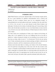
<strong>IJREAS</strong> <strong>Volume</strong> 2, <strong>Issue</strong> 2 (<strong>February</strong> <strong>2012</strong>) <strong>ISSN</strong>: 2249-3905remaining. A code tree is thus generated and the Huffman code is obtained from the labelingof the code tree. An example of how this is done is shown below in fig.1Fig. 1 Huffman treeSteps for Huffman Coding:1. Arrange the source symbols in a decreasing order of their probability.2. Take the bottom two symbols and tie them together. Add probabilities of two symbolsand write it on the combined node. Label the two branches with a „1‟ or „0‟ as shownin figure below.3. Treat this probability as a new probability of combined symbol and repeat previousstep till we have a single symbol, and whenever we tie together two probabilities welabel the two branches with a „1‟ or „0‟.4. This will complete the construction of Huffman tree.5. To find out the prefix code for any symbol follow the branches from the final nodeback to the symbol. While tracking back the route read out the labels on the branches.This is the codeword for the symbol.Although Huffman's original algorithm is optimal for a symbol-by-symbol coding (i.e. astream of unrelated symbols) with a known input probability distribution, it is not optimalwhen the symbol-by-symbol restriction is dropped, or when the probability mass functionsare unknown.III. IMAGE COMPRESSIONDigital images are characterized by multiple parameters. The first feature of a digital image isits colour mode. A digital image can have one of three modes: binary, gray scale or colour. Abinary (bi-level) image is an image in which only two possible values for each pixel. A grayscale image means that its each pixel can contain only a tint of gray colour. A digital image isa set of pixels. Each pixel has a value that defines colour of the pixel. All the pixels areInternational Journal of Research in Engineering & Applied Sciences 654http://www.euroasiapub.<strong>org</strong>
<strong>IJREAS</strong> <strong>Volume</strong> 2, <strong>Issue</strong> 2 (<strong>February</strong> <strong>2012</strong>) <strong>ISSN</strong>: 2249-3905composed into one array. There are several different ways in which image files can becompressed.A. Different Compression Methods for Image dataImage compression was first used to deal with the limited memories of the first personalcomputers and the large file size of colour images. Compression algorithms were proposedand developed.1) Image Compression: JPEGJPEG is well known standard when we are concerned to images. Joint Pictures Expert Groupdeveloped a lossy image source coding technique which came into existence as JPEG in1992. JPEG can work with grayscale as well as color images. JPEG can compress image to aslittle as two to five percent of its original file size, but as the degree of compression increases,there is a corresponding loss of image quality.JPEG involves a number of steps which are as follows:I. Discrete Cosine TransformII.III.IV.QuantizationZigzag scanEncodinga. DPCM on DC Componentsb. RLE on AC componentsV. Entropy CodingAll of the above steps ensure the compression to be fully effective, but most of thecompression is done in the first three steps. In fact, DCT i.e. Discrete Cosine Transform is themost important process used in JPEG. The reason why the steps IV and V are not “soimportant” is because of the fact that these steps are merely compressio n techniques whichwork on some kind of redundancies/similarity in the pixels and we can use any of the codingtechniques.So our main concern, here, is the first three steps of JPEG. We can compress an image byapplying DCT to the pixels of the image and then quantizing it. Although, most of thecompression is done by the quantization itself but it is DCT who makes the quantization veryeffective in terms of image compression.2) Discrete Cosine TransformDiscrete Cosine Transform expresses a sequence of finitely many data points, in our casepixels, in terms of cosine function oscillating at different frequencies. DCT converts the datavalues in term of spatial frequencies. Each spatial frequency indicates the number of timesInternational Journal of Research in Engineering & Applied Sciences 655http://www.euroasiapub.<strong>org</strong>
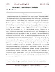
<strong>IJREAS</strong> <strong>Volume</strong> 2, <strong>Issue</strong> 2 (<strong>February</strong> <strong>2012</strong>) <strong>ISSN</strong>: 2249-3905the pixel value changes in a data block, usually 8×8 block. DCT formalizes spatialfrequencies by measuring how much the image content i.e. the pixel values changesaccording to the number of cosine cycles per block.Discrete Cosine Transform is given mathematically as:Where C (u) and C (v) =f (i, j) is original pixel coefficient at coordinates (i, j) in the N N block of image.F (u, v) is the DCT coefficient at coordinates (u, v).DCT concentrate the useful information of image in first several component of the block,usually in the upper-left part of the Discrete Cosine Transformed block.F(0, 0) is called AC coefficient and all other coefficients are called DC coefficients.The principal cause of using DCT in image compression is the way humans see an ima ge. Itis a proved phenomenon that human eyes are less sensitive to the high spatial frequencies.The content which is useful changes relatively slow. Usually the high spatial frequenciescorrespond to the rders/outlines of the objects in the image. So we can remove the highspatial frequency components, or try to lessen their quantity, to compress the image. Thisdoes not change the image significantly in terms of the quality. But it greatly helps inreducing the file size when quantization occurs.Quantization is the main source of compression in this whole process. It will generatemathematically as:F(u,v) is the Discrete Cosine Transformed entry at coordinates (u, v), also called as DCTcoefficient. Q(u,v) is a Quantization Table entry at coordinates (u, v).As we can decide the value of Q (u, v), we can achieve a variable compression. Increasingthe value of Q (u, v) will increase the compression and decreasing Q(u,v) will decrease thecompression.We can choose the value of the Q(u,v) by ourselves. However in JPEG it is predefined asshown in the fig. 2.After quantization a zigzag scan is performed just to efficiently convert the DCT coefficientsin a bit stream.International Journal of Research in Engineering & Applied Sciences 656http://www.euroasiapub.<strong>org</strong>
<strong>IJREAS</strong> <strong>Volume</strong> 2, <strong>Issue</strong> 2 (<strong>February</strong> <strong>2012</strong>) <strong>ISSN</strong>: 2249-3905Based on the PSNR (Peak Signal to Noise Ratio) of the compressed images, we conclude thepros and cons of DCT image compression, and jpeg too.161110162440516112121419265860551413162440576056Q=1418172222372956516887109801036277243555648110411392496478871031211201017292959811210010399Fig 2. Quantization matrixBased on the PSNR (Peak Signal to Noise Ratio) of the compressed images, we conclude thepros and cons of DCT image compression, and jpeg too.One of main advantages of DCT compression is that the fidelity of an image does not changemuch when the scale of quantization is within the limits.Compression up to any level can be achieved. i.e. we can reduce the size of image even up to2% of the original size. But as compression is increased psnr also increases simultaneouslywhich means a high image noise. Although we have done analysis of DCT compressionapplying it on grayscale images, but it can also be applied to RGB images. On RGB, itsperformance will be better as compared to grayscale.This image compression is also flexible as it can be implemented using any types of hardwareand software. Also, as the output after the zigzag scan is a bit stream it will be easy to seriallytransmit the image to other devices.It‟s a lossy compression method, so we cannot exactly reconstruct the image. So it cannot beused to compress critically important data like medical imaging.3) Wavelet CompressionWavelet compression is relatively new method. It is powerful tool for compressinginformation. This compression technology is used in the JPEG-2000 standards. Imagescompressed using wavelets are smaller than JPEG images and can be transferred faster.Wavelet technology can compress color images from 20:1 to 300:1 and grey scale imagesfrom 10:1 to 50:1.Wavelet transformation is similar in principal to the DCT based compression. The maindifference is the use of wavelet based mathematical technique in place of DCTtransformations. In contrast to JPEG, wavelet algorithm does not divide an image into blocks,International Journal of Research in Engineering & Applied Sciences 657http://www.euroasiapub.<strong>org</strong>
<strong>IJREAS</strong> <strong>Volume</strong> 2, <strong>Issue</strong> 2 (<strong>February</strong> <strong>2012</strong>) <strong>ISSN</strong>: 2249-3905but analyze the whole image. This characteristic of wavelet compression helps to get the bestcompression ratio, while maintaining the quality.Procedure: Wavelets represent pictures as wave that can be described mathematically interms of frequency, energy and time. They have advantages over traditional Fourier and DCTmethods in analyzing signals that have discontinuities and spikes. The advanced mathematicsunderlying wavelet transformation is very complex. Therefore, for the purpose we willintroduce the concept in very simple terms without using mathematical formulations.The steps needed to compress an image using wavelet transformation are as follow:1) The source image is digitized into a signal, a string of numbers „s‟.2) The signal is then decomposed into sequence of wavelet coefficients „w‟.3) Thresholding is used to modify the wavelet coefficients from w to another sequencew‟.4) Using quantization the sequence w‟ is converted to a sequence q.5) Finally entropy coding is applied to compress q into a sequence e.Example: For the purpose of understanding wavelet compression, assume we have a onedimensionalimage consisting of just four pixels in a row. Assume that the four pixels in rowhave different shades of grey of value: 3, 5, 9, 7.We could take the average of the first pair and then the average of the second pair to give: 4,8. Here in effect, we have simplified the image by halving its resolution. But in the process,some information is lost. In order to restore the original values we would need to record thedifferences as well as the averages. These are known as the „detail coefficients‟. The detailcoefficients are added to and subtracted from averages in order to reconstruct the originalvalues.For the case we assumed, the detail coefficients are -1 and 1; calculated as: (3 -5)/2 and (9-7)/2.Thus from the second pair we get back the original values: 4+ -1=3; 4- -1=5; 8+1=9; 8-1=7.We can keep on decomposing the image in a similar way by taking the averages and notingthe average differences. Soon we will arrive at one overall average and one set of detailcoefficients. In this simple example, the image can be decomposed once more, giving thevalues: overall average 6 and the difference 2.International Journal of Research in Engineering & Applied Sciences 658http://www.euroasiapub.<strong>org</strong>
<strong>IJREAS</strong> <strong>Volume</strong> 2, <strong>Issue</strong> 2 (<strong>February</strong> <strong>2012</strong>) <strong>ISSN</strong>: 2249-3905Resolution Averages Detailcoefficients4 (original 3,5,9,7image)2 (half 4,8 -1,1resolution)1 (coarsest 6 2image)Table1. DWT coefficientsThus, if we recorded the overall average (6) and the detail coefficients, we would haveenough information to reconstruct the image at half resolution (4,8) or full resolution(3,5,9,7). The data therefore will be: 6;2,-1,1.(Average:6; Detail coefficients:2,-1,1).The image described by this information is lossless, since it can b reconstructed exactly as itwas. It will be lossy if we keep the significant detail and throw away other detail coefficientsof the image. This would produce smaller files that appear as good as original whendecomposed. The result would be a lossy compressed image.4) Discrete wavelets transform:In discrete wavelet transformation (DWT) method an image is represented as a twodimensional array of coefficients, where each coefficient represents the brightness level of apoint or pixel of that image. Most natural images have smooth color variations (lowfrequency variations). From compression point of view, the low frequency components are ofmore importance. DWT plays a very important role in extracting these low frequencycomponents.The DWT of a signal is obtained by passing it through two filters that are related to eachother. Such filter-pair is known as analysis filter. When a digitized signal is thus filtered, halfthe samples can be discarded according to Nyquist‟s rule. So the filter outp uts are downsampled by 2. The signal is passed simultaneously through a low pass filter and high passfilter. The low pass filter (LPF) gives the approximation coefficients (averages) and high passfilter (HPF) gives the detail coefficients. The approximation coefficients (outputs of the firstlevel LPF) can be further decomposed with the second level analysis filter. Adding more andmore levels, a filter bank can be constructed that can look like a binary tree.International Journal of Research in Engineering & Applied Sciences 659http://www.euroasiapub.<strong>org</strong>
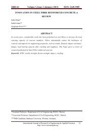
<strong>IJREAS</strong> <strong>Volume</strong> 2, <strong>Issue</strong> 2 (<strong>February</strong> <strong>2012</strong>) <strong>ISSN</strong>: 2249-3905DWT of an image: in order to obtain DWT of an image, first the lpf and HPF are applied foreach row data. The procedure is repeated for all the rows and all low pass and high passcomponents are collected and placed side by side. Thereafter, the filtering is repeated for eachcolumn of the intermediate data. The resulting two-dimensional array of coefficients contain4 bands of data labeled as LL(low-low), HL,LH and HH(high-high).repeated transformprocedure produce the pyramidal decomposition of the image.The LL band at the top of the pyramid is of most importance in representing the image andthe degree of importance decreases as we move down.To reconstruct the image a reverse transform of DWT is used to reassemble the varioussegments of data. For this reverse transformation a synthesis filter pair is used, whichfunctions exactly as the opposite to the analysis filter. Starting from the topmost level, thefilter actions are applied column-wise first and then the row-wise.the DWT of a picture canbe obtained easily by software written in either Java or C language. MATLAB can also beused.Digital images are characterized by multiple parameters. The first feature of a digital image isits colour mode. A digital image can have one of three modes: binary, gray scale or colour. Abinary (bi-level) image is an image in which only two possible values for each pixel. A grayscale image means that its each pixel can contain only a tint of gray colour. A digital image isa set of pixels. Each pixel has a value that defines colour of the pixel. All the pixels arecomposed into one array. There are several different ways in which image files can becompressed.IV. IMPLEMENTATIONCompression methods mentioned for text and image data are implemented in MATLAB.RLE and Huffman coding methods are applied to the same text data and DCT compressionand Wavelet compression is applied to same image data.Following fig. represents the implementation of RLE and Huffman encoding technique ontext data and compression ratio is calculated.International Journal of Research in Engineering & Applied Sciences 660http://www.euroasiapub.<strong>org</strong>
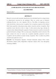
<strong>IJREAS</strong> <strong>Volume</strong> 2, <strong>Issue</strong> 2 (<strong>February</strong> <strong>2012</strong>) <strong>ISSN</strong>: 2249-3905Fig. 3 Compression of text data using RLE and Huffman codingGraphical representation of compression ratio of text data compression is shown in figurebelow.Fig.4 Comparison of Compression RatioFig. 5 Comparisons of Input and Output Bits of RLE and HuffmanInternational Journal of Research in Engineering & Applied Sciences 661http://www.euroasiapub.<strong>org</strong>
<strong>IJREAS</strong> <strong>Volume</strong> 2, <strong>Issue</strong> 2 (<strong>February</strong> <strong>2012</strong>) <strong>ISSN</strong>: 2249-3905Following figures represents the implementation of DCT compression technique.Fig. 6 Compressed image using DCTFollowing figures represents the implementation of wavelet compression technique.V. CONCLUSIONFig. 7 Compressed image using waveletIn this thesis Comparative analysis of compression methods is carried out. Comparativeanalysis is done on the basis of two parameters compression ratio and compression quality.Our results illustrate that we can achieve higher compression ratio for Huffman encoding.RLE compression is not better for data which does not contain long runs but Huffmanencoding is showing better result with any kind of text data. Wavelet compression techniqueshows better result as compared to the DCT compression technique and gives bettercompression ratio and PSNR value.VI. FUTURE WORKIn future this thesis can be extended by comparing compression methods that are mentionedin this thesis with the Image segmentation. Comparison can be made on the basis of memoryspace taken by Compressed image and Segmented image. Segmentation refers to the processof partitioning a digital image into multiple segments (sets of pixels) (Also known as superpixels). The goal of segmentation is to simplify and change the representation of an imageinto something that is more meaningful and easier to analyze. Image segmentation is typicallyused to locate objects and boundaries (lines, curves, etc.) in images. More precisely, imagesegmentation is the process of assigning a label to every pixel in an image such that pixelswith the same label share certain visual characteristics. The goal of image segmentation is toInternational Journal of Research in Engineering & Applied Sciences 662http://www.euroasiapub.<strong>org</strong>
<strong>IJREAS</strong> <strong>Volume</strong> 2, <strong>Issue</strong> 2 (<strong>February</strong> <strong>2012</strong>) <strong>ISSN</strong>: 2249-3905cluster pixels into salient image regions, i.e., regions corresponding to individual surfaces,objects, or natural parts of objectsREFERENCES1. S. W. Golomb, “Run-Length Encoding,” IEEE Trans. Info. Theory IT-12, 399-401(July 1966)2. S. Akhter and M.A. Haque. ECG Compression using Run Length Encoding. Europeansignal processing (EUSIPCO-2010), pp. 1645-1649, August 23-27, 20103. R.G. Gallager, “Variations on a theme by Huffman”, IEEE Trans. Information Theory,Vol. IT-24, no 6, pp 668-674, Nov. 19784. O. Johnsen, “On the redundancy of binary Huffman codes”, IEEE Trans. Inform..Theory, Vol. IT-26, no 2, pp 220-223, Mar 19805. Ashok Banerji, Ananda Mohan Ghosh “Multimedia Technologies”, by Tata McGrawHill, pp 79-816. X. Kavousianos, E. Kalligeros, and D. Nikolos, “Optimal Selective Huffman Coding forText-Data Compression” IEEE Transactions on Computers,vol.56, pp. 1146-1152, Aug20077. Se-Kee Kil, Jong-Shill Lee, Dong-Fan Shen, Je-Goon Ryu, Eung-Hyuk Lee, Hong-KiMin, Seung-Hong Hong “Lossless Medical Image Compression using RedundancyAnalysis” , IJCSNS International Journal of Computer Science and Network Security,Vol.6 No.1A, pp. 50-57, January 20068. Digital Compression and coding of Continuous-tone still images, part 1, requirementsand Guidelines. ISO/IEC JTC1 Draft International Standard 10918-1, Nov. 19919. N. Ahmed, T. Natrajan, and K. R. Rao, “Discrete Cosine Transform”, IEEETransactions on Computers, vol. 23, July 198910. Lewis AS, Knowles G Image compression using the 2-d wavelet transform IEEE transimage processing vol.1 no 2 april 199211. Monro, D.M and Sherlock, B.G., „Optimal quantization statergy for DWT imagecompression‟ IEEE proceedings- Vision, Image and Signal processing 1999International Journal of Research in Engineering & Applied Sciences 663http://www.euroasiapub.<strong>org</strong>