Foot design for a hexapod walking robot - PAR
Foot design for a hexapod walking robot - PAR
Foot design for a hexapod walking robot - PAR

Create successful ePaper yourself
Turn your PDF publications into a flip-book with our unique Google optimized e-Paper software.
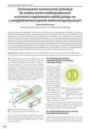
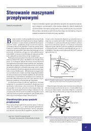
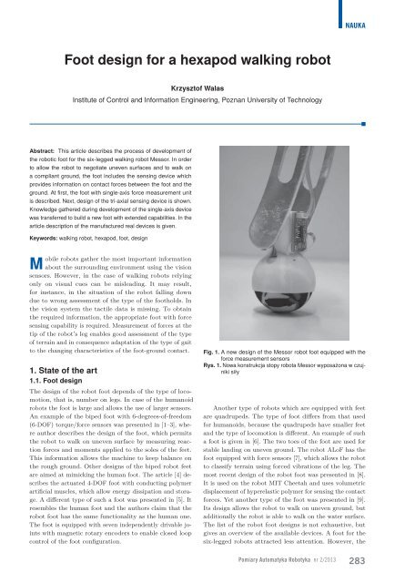
3. The three-axis sensorIn order to obtain comprehensive in<strong>for</strong>mation about thereaction <strong>for</strong>ce vector, a different foot <strong>design</strong> than presentedpreviously was required. The complete vector can be obtainedusing at least three Force Resistive Sensors placed inthe <strong>robot</strong> foot. In our approach two mechanical <strong>design</strong>s ofthe foot were proposed, which differ as to the number andlayout of the sensors.3.1. DesignThe new foot <strong>design</strong> is based on the ball of diameter of45 mm, made of the foam rubber. The rubber has moderatestiffness. The ball fits into the socket made of plasticAcrylonitrile Butadiene Styrene (ABS). In the upper partof the foot the cuboid-shaped fixing was <strong>design</strong>ed. It allowsto mount signal conditioning devices required to obtainlinear output characteristics of the <strong>for</strong>ce measurements.The new <strong>robot</strong> foot with the printed circuit mounted on itis shown in fig. 6. The height of the foot is 73 mm.In fig. 6 mechanical <strong>design</strong> of the third version of thefoot model is presented. It contains five Force ResistiveSensors, with two of them placed at the intersections ofpositive and negative part of the x axis with the surfaceof the ball socket. Another two sensors are mounted atthe intersections of the ball socket surface with positiveand negative part of the y axis. One sensor is fixed atthe intersection of the positive part of the z axis with thesurface of the ball socket. The adopted local coordinateframe <strong>for</strong> the foot is shown in fig. 7. In the version (b) ofthe foot <strong>design</strong>, three <strong>for</strong>ce sensors equally spaced aroundthe socket were used. The sensors are placed on the surfaceof the ball socket every 120 ◦ of the full angle around z axis(see fig. 7). Each of the sensors is tilted at 45 ◦ from thexy plane, which cuts the ball in half. The location of eachsensor is shown in fig. 7, the vectors F 1, F 2, F 3 denote the<strong>for</strong>ces acting on each FSR.3.2. 3D printingThe <strong>design</strong>ed shape of the sockets with sensors mountedinside is hard to obtain using the conventional millingmachine. The volume of the material to be removed is verylarge. As an alternative, the socket may be manufacturedin the casting process. However, this process is rathertime-consuming and requires preparation of the mold,which has to be manufactured in the milling process. Inorder to obtain parts in a short period of time, the rapidprototyping techniques can be used. The sockets presentedin this article were manufactured directly from the computerFig. 6. The third model of the <strong>robot</strong> foot with <strong>for</strong>ce sensors andsignal conditioning devices mounted on itRys. 6. Trzeci model stopy <strong>robot</strong>a z zamontowanymi czujnikamii układami kondycjonowania sygnałumodel using a 3D printer. The material used <strong>for</strong> the parts isthe white ABS. Machine used in the fabrication process isthe Stratasys Dimension 1200es. Thickness of a single layeris equal to 0.254 mm (0.01 inch). Wall of the sockets dueto properties of the technological process has to be 2 mmthick. Moreover, to build such a part of a spherical shape,a supporting material has to be used to support upperlayers of the part during the printing process. In the crust ofthe socket, thin extrusions were made <strong>for</strong> fixing the sensors.5.14.94.74.54.34.13.93.73.53.33.12.92.72.52.32.11.90 0.2 0.4 0.6 0.8 1 1.2 1.4 1.6 1.8 2 2.2 2.42.5 Fig. 5. The second model of the foot. Linear output of the <strong>for</strong>cemeasurement systemRys. 5. Drugi model stopy. Liniowa charakterystyka odpowiedziukładu pomiaru siłyFig. 7. Local coordinate frame <strong>for</strong> the foot. Forces F 1 , F 2 , F 3 pointat each FSRRys. 7. Lokalny układ odniesienia dla stopy. Siły F 1 , F 2 , F 3 wskazująna każdy FSRPomiary Automatyka Robotyka nr 2/2013285
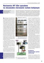
NAUKAFig. 8. Inner side of the ball socket of the foot. Version (a) with five<strong>for</strong>ce sensors, version (b) with three <strong>for</strong>ce sensorsRys. 8. Wewnętrzna strona gniazda stopy. Wersja (a) z pięciomaczujnikami siły, wersja (b) z trzema czujnikami siłyThe depth of the extrusions allows to obtain a smoothsurface of the inner side of the socket in order to get arepeatable shape of the contact area between the ball andthe <strong>for</strong>ce sensor. The small rectangular holes provide accessto the mounting pads of the FSR. The inner side of thesocket obtained in 3D printing is shown in fig. 8. The leftfigure shows the <strong>design</strong> with five sensors (version (a)),whereas the right figure – with three sensors (version (b)).3.3. Electronics <strong>design</strong>For the sake of achieving full functionality of the mechatronicsystem, the mechanical <strong>design</strong> has to be supportedby the appropriate <strong>design</strong> of electronic circuits. In our caseelectronic schematic shown in fig. 3 was reused in thethird model of the foot. The circuit was copied twice andit was possible to connect two sensors to the same printedcircuit board (PCB). The foot with mounted PCB isshown in fig. 6. Tight limits on dimensions of the board resultedin the PCB of size 28 x 19.3 mm. A single chip withquad operational amplifiers was used on the PCB. This allowedto reduce the dimensions of the board. The outputof the circuit is the voltage signal. This signal can be directlyconnected to the analogue-to-digital converter (ADC)of the <strong>robot</strong> controller. The other possibility is the connectionto the ADC on the leg of the <strong>robot</strong> and transmissionof the signal via digital interface (I2C, SPI) or using theZigBee wireless technology (IEEE 802.15.4). The ZigBeemodules, i.e. ATZB-24-A2, are equipped with ADC converters(3 input lines), so it is possible to connect the voltagesignals directly to the ZigBee module and to send the valuesvia wireless transfer protocol. These signals are easilyaccessible through AT commands from BitClouds software.Advantage of this solution is lack of wires connected tothe foot, except <strong>for</strong> the power wires. What is more, the in<strong>for</strong>mationon the contact <strong>for</strong>ces can be acquired both onboard of the <strong>robot</strong> and on a remote host.4. ConclusionsThe article describes the process of the <strong>walking</strong> <strong>robot</strong> foot<strong>design</strong>. The model of the foot with single-axis <strong>for</strong>ce sensorwas shown. The improved version of the first <strong>design</strong> solvesthe problems of non-linearity of sensor readings as wellas copes with the non-uni<strong>for</strong>m <strong>for</strong>ce distribution on thesensor pad. Experience gained during the developmentFig. 9. The future <strong>design</strong> of the foot with 6-DOF <strong>for</strong>ce/torque measurementunitRys. 9. Projekt stopy z sześcioosiowym czujnikiem siła/momentof the foot with single-axis <strong>for</strong>ce sensor allowed to buildthe new foot with tri-axial <strong>for</strong>ce sensor. Two <strong>design</strong>s wereproposed: one with five FSRs (Force Sensitive Resistors) andthe other with three FSRs. The first solution gives directin<strong>for</strong>mation about the <strong>for</strong>ce along each axis. The secondone requires per<strong>for</strong>ming some computations to obtain theelements of the <strong>for</strong>ce vector but involves only three sensors.It also sacrifices the angular range of <strong>for</strong>ces, which this timecan be measured by means of only three sensors tilted by45 ◦ .4.1. Future workThe presented foot requires extensive tests on the <strong>robot</strong> indifferent conditions to obtain durable and reliable measuringdevice. Development of the foot with the sensors whichpermit 6-DOF <strong>for</strong>ce/torque measurements is envisaged asa future work. Initial stages of the <strong>design</strong> have been alreadycompleted. The foot is suspended on permanent magnets(ball). The <strong>for</strong>ce and torque measurements are based onstretch sensors and the effect of bending of the bottompart of the foot which is compliant. The model of a futuredevice like that is shown in fig. 9.AcknowledgementsThis work was supported by the National Science Centre ofthe Republic of Poland, Grant No. 2011/01/N/ST7/02070.I would like to thank my students who have helped me withthe <strong>design</strong> of the improved 1-DOF foot Piotr Gendoła andMarek Czachorowski, as well as Bartłomiej Orczykowski<strong>for</strong> helping me with the <strong>design</strong> of the future 6-DOF foot.References1. Kim G.-S., Shin H.-J., Yoon J., Development of 6-axisForce/Moment Sensor <strong>for</strong> Humanoid Robot’s <strong>Foot</strong>, [in:]IEEE Sensors, October, 2007, 217–220.2. Kim G.-S., Development of 6-axis <strong>for</strong>ce/moment sensor<strong>for</strong> a humanoid <strong>robot</strong>’s foot, ”Science, MeasurementTechnology, IET”, Vol. 2, No. 3, 2008, 122–133.3. Kim G.-S., Yoon J., Development of intelligent footwith six-axis <strong>for</strong>ce/moment sensors <strong>for</strong> humanoid <strong>robot</strong>,[in:] IEEE International Conference on Robotics andBiomimetics (ROBIO), February, 2009, 939–944.286
4. Secord T., Asada H., A Humanoid <strong>Foot</strong> with PolypyrroleConducting Polymer Artificial Muscles <strong>for</strong> EnergyDissipation and Storage, [in:] IEEE International Conferenceon Robotics and Automation (ICRA), April,2007, 2904–2909.5. Davis S., Caldwell D., The <strong>design</strong> of an anthropomorphicdexterous humanoid foot, [in:] IEEE/RSJ InternationalConference on Intelligent Robots and Systems(IROS), October, 2010, 2200–2205.6. Hong Y., Yi S., Ryu S., Lee C., Design and experimentaltest of a new <strong>robot</strong> foot <strong>for</strong> a quadrupedal jointed-leg type<strong>walking</strong> <strong>robot</strong>, [in:]5 th IEEE International Workshop onRobot and Human Communication, November, 1996,317–322.7. Hoepflinger M., Remy C., Hutter M., Spinello L.,Siegwart R., Haptic terrain classification <strong>for</strong> legged<strong>robot</strong>s, [in:] IEEE International Conference on Roboticsand Automation (ICRA), May, 2010, 2828–2833.8. Chuah M. Y. M., Estrada M., Kim S., CompositeForce Sensing <strong>Foot</strong> Utilizing Volumetric Displacementof a Hyperelastic Polymer, [in:] IEEE/RSJ InternationalConference on Intelligent Robots and Systems (IROS),October, 2012, 1963–1969.9. Park H. S., Sitti M., Compliant footpad <strong>design</strong> analysis<strong>for</strong> a bio-inspired quadruped amphibious <strong>robot</strong>,[in:] IEEE/RSJ International Conference on IntelligentRobots and Systems (IROS), October, 2009, 645–651.10. FSR Force Sensing Resistor Integration Guide andEvaluation Parts Catalog, Interlink Electronics.11. Evan D., Design of Plantar Force Sensor <strong>for</strong> AnkleRehabilitation Monitor, EE4BI6 Electrical EngineeringBiomedical Capstones. Paper 42, 2010.12. Moon S.-C., Lee C.-H., Lee S.-G., A study of knee bracelocking timing and <strong>walking</strong> pattern detected from anFSR and knee joint angle, [in:] 11 th International Conferenceon Control, Automation and Systems (ICCAS),October, 2011.13. Rana N., Application of Force Sensing Resistor (FSR)in Design of Pressure Scanning System <strong>for</strong> PlantarPressure Measurement, [in:] Second International Conferenceon Computer and Electrical Engineering, December,2009, 678–685.14. Ogris G., Kreil M., Lukowicz P., Using FSR basedmuscule activity monitoring to recognize manipulativearm gestures, [in:] 11 th IEEE International Symposiumon Wearable Computers, October, 2007, 45–48.15. Desai A., Payandeh S., Vaisey J., On the localizationof objects using an FSR pressure pad transducer, [in:]IEEE International Conference on Systems, Man, andCybernetics, 1994, Humans, In<strong>for</strong>mation and Technology,October, 1994, 953–957.16. Stewart C., Rohs M., Kratz S., Essl G., Characteristicsof pressure-based input <strong>for</strong> mobile devices, [in:] Proceedingsof the SIGCHI Conference on Human Factorsin Computing Systems, ACM, New York, NY, USA,April, 2010, 801–810.17. Bosi M., Jordà S.,Towards fast multi-point <strong>for</strong>ce and hitdetection in tabletops using mechanically intercoupledForce Sensing Resistors, [in:] NIME’12, Ann Arbor,Michigan, USA, May, 2012.18. Zehr E., Stein R., Komiyama T., Kenwell Z., Linearizationof <strong>for</strong>ce sensing resistors (FSR’s) <strong>for</strong> <strong>for</strong>cemeasurement during gait, [in:] Engineering in Medicineand Biology Society, 1995, IEEE 17 th Annual Conference,September, 1995, 1571–1572.19. Florez J., Velasquez A., Calibration of <strong>for</strong>ce sensingresistors (FSR) <strong>for</strong> static and dynamic applications,[in:] ANDESCON, 2010 IEEE, September, 2010, 1–6.20. Lebosse C., Renaud P., Bayle B., de Mathelin M.,Modeling and Evaluation of Low-Cost Force Sensors,”IEEE Transactions on Robotics”, Vol. 27, No.4, 2011,815–822.21. Krkljes D., Nagy L., Babkovic K., Force-dependentcontact area excitation of FSR <strong>for</strong>ce sensor utilizingdome-shaped rubber element, [in:] 28 th InternationalConference on Microelectronics (MIEL), May, 2012,181–184.22. Walas K., Belter D., Messor – Versatile Walking Robot<strong>for</strong> Search and Rescue Missions, ”Journal of Automation,Mobile Robotics & Intelligent Systems”, Vol. 5,No. 2, 2011, 28–34.23. Walas K., Belter D., Supporting locomotive functions ofa six-legged <strong>walking</strong> <strong>robot</strong>, ”Int. J. Appl. Math. Comput.Sci.”, Vol. 21, No. 2, 2011, 363–377.Projekt stopy sześcionożnego <strong>robot</strong>a kroczącegoStreszczenie: Niniejszy artykuł opisuje proces rozwoju stopydla sześcionożnego <strong>robot</strong>a kroczącego Messor. Stopa posiadawbudowane urządzenie do pomiaru sił kontaktu pomiędzy stopąa podłożem. Dane te są wymagane do kroczenia po nierównymi podatnym gruncie. W artykule pokazane zostało jednoosioweurządzenie pomiarowe. Następnie opisany został czujnik trójosiowybazujący na projekcie czujnika jednoosiowego. Artykuł prezentujeproces projektowania jak i opis rzeczywistego urządzenia.Słowa kluczowe:projektowanieKrzysztof Walas, PhDKrzysztof Walas received the MSc and PhDdegrees in control engineering and <strong>robot</strong>icsfrom the Poznan University of Technologyrespectively in 2007 and 2012. Heiscurrentlyan assistant professor at the Instituteof Control and In<strong>for</strong>mation Engineering ofthe same university. His research interestsinclude <strong>walking</strong> <strong>robot</strong>s control, multisensorenvironment perception <strong>for</strong> navigation purposesand machine vision.e-mail: krzysztof.walas@put.poznan.pl<strong>robot</strong> kroczący, <strong>robot</strong> sześcionożny, stopa,Pomiary Automatyka Robotyka nr 2/2013287