Experiment AN-2: Compound Action Potentials - iWorx
Experiment AN-2: Compound Action Potentials - iWorx
Experiment AN-2: Compound Action Potentials - iWorx

Create successful ePaper yourself
Turn your PDF publications into a flip-book with our unique Google optimized e-Paper software.
8. If a compound action potential is not detected at stimulus amplitude of 0.050V, increase thestimulus amplitude (Amp) by an increment of 0.050V. Record and mark the response of thenerve.9. Repeat Step 8 until the threshold response of the nerve is detected. Mark this sweep of therecording with the term, Threshold.10. Once the threshold response of the compound nerve is found, continue to increase the stimulusamplitude (Amp) in 0.050V increments until the maximal response of the nerve is observed.Change voltages, record sweeps, and mark recordings in the same manner as before.Note: C fibers have thresholds and latencies up to 30 times higher than those of A fibers. Therefore,higher stimulus amplitudes and longer display times may be required to see C fibers.11. Select Save in the File menu.12. Fill the nerve chamber with fresh Ringer's solution to prevent the dessication of the nerve.Exercise 3: Conduction VelocityAim: To measure the velocity of action potential conduction.Procedure1. Change the stimulus amplitude (Amp) to the lowest voltage that creates a maximal compoundaction potential. Click the Apply button to finalize the change in the stimulus amplitude.2. If necessary, lower the level of Ringer’s solution in the nerve bath chamber below the nerve andblot any drops of solution from the preparation as described in Exercise 1.3. Connect the black (-1) recording lead wire to the first recording electrode that is next to theground electrode. Make sure the red (+1) recording lead wire is on the outermost recordingelectrode.4. Click Record to stimulate the nerve. Type Short Path in the Mark box to the right of the Markbutton. Press the Enter key on the keyboard to attach this notation to the recording.5. Move the black (-1) recording lead wire to another recording electrode that is farther from theground electrode. Do not move the red (+1) recording lead wire.6. Click Record to stimulate the nerve. Type Long Path in the Mark box to the right of the Markbutton. Press the Enter key on the keyboard to attach this notation to the recording.7. Measure the distance between the two positions of the negative (-1) recording electrode.8. Select Save in the File menu.9. Fill the nerve chamber with cold Ringer’s solution and chill the nerve for ten minutes beforeperforming Exercise 4.<strong>iWorx</strong> Sample LabAnimal Nerve – <strong>Compound</strong> <strong>Action</strong> Potential – Labs<strong>AN</strong>-2-4Copyright <strong>iWorx</strong> Systems Inc.Note: Only for evaluation by prospective customers.
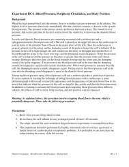
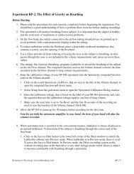
Figure <strong>AN</strong>-2-L4: Two sweeps used to determine the conduction velocity of the nerve.Exercise 4: Conduction Velocity and TemperatureAim: To examine the effects of cooling on the conduction velocity of a cold nerve.ProcedureNote: This part of the experiment must be done quickly since the nerve will begin to warm as soon asthe bath is drained.1. Lower the level of cold Ringer’s solution in the nerve bath chamber below the nerve and blotany drops of solution from the preparation as described in Exercise 1.2. As soon as the cold Ringer’s has been removed from the nerve bath chamber, measure theconduction velocity of the nerve using the same procedures used in Exercise 3.3. After data for this exercise is recorded, fill the nerve bath chamber with room temperatureRinger’s solution. As you are waiting for the nerve to warm up to room temperature, programthe stimulator to the parameters needed in the next exercise.Exercise 5: Refractory PeriodAim: To measure the effect of stimulus frequency on the amplitudes of the compound action potentials.Note: In the short period of time after an axon generates an action potential, the axon is unable togenerate a second action potential. This period of time, in which the axon is not responsive to anystrength of stimulus, is known as the absolute refractory period. With additional time to recover, the<strong>iWorx</strong> Sample LabAnimal Nerve – <strong>Compound</strong> <strong>Action</strong> Potential – Labs<strong>AN</strong>-2-5Copyright <strong>iWorx</strong> Systems Inc.Note: Only for evaluation by prospective customers.
axon is able to generate a second action potential, but the strength of the stimulus needed is greaterthan the threshold stimulus that can normally trigger an action potential. This period, in which theresponsiveness of the axon is reduced, is known as the relative refractory period. As the axon is givenmore time to recover, the strength of the stimulus required to trigger a second action potentialdecreases. In fact, the end of the relative refractory period is defined as the time when the stimulusrequired to trigger the second action potential is the same as the threshold stimulus that triggered thefirst action potential.Nerves are composed of axons of different diameters, conduction velocities, thresholds, and refractoryperiods. In the short period of time after a nerve generates a compound action potential, none of theaxons in the nerve are able to generate a second action potential because all the axons are within theirabsolute refractory periods. As time passes, the axons with lower thresholds and shorter refractoryperiods will generate action potentials when the same stimulus pulse is delivered to the nerve. As moretime passes, more axons recover and more axons can generate action potentials with the same stimuluspulse.Procedure1. Adjust the critical stimulus parameters to the values listed in Table <strong>AN</strong>-2-L1 using the sametechniques used in earlier exercises. The stimulus amplitude must be set to a voltage that willgenerate compound action potentials with maximal amplitudes as determined in previousexercises. Click the Apply button to finalize the changes to these stimulus parameters.Table <strong>AN</strong>-2-L1: Stimulus Parameters Required for Measuring the Refractoriness of the Nerve.Stimulus ParameterStimulus Amplitude (Amp)ValueVolts for Max CAPNumber of Pulses (#pulses) 2Pulse Width (W)Time Between Pulses (T Off)0.1 msec10 msecHolding Potential (HP) 02. If necessary, lower the level of Ringer’s solution in the nerve bath chamber below the nerve andblot any drops of solution from the preparation as described in Exercise 1.3. Click Record to stimulate the nerve. Type 10 msec Interval in the Mark box to the right of theMark button. Press the Enter key on the keyboard to attach this notation to the recording.4. Change the time interval between stimulus pulses (T Off) to 9 msec. Click the Apply button tofinalize this change.5. Click Record to stimulate the nerve. Type 9 msec Interval in the Mark box. Press the Enter keyon the keyboard to attach this notation to the recording.<strong>iWorx</strong> Sample Lab6. Repeat Steps 4 and 5 to record the change in the amplitude of the second compound actionpotential as the time interval between the two stimuli in the pair is decreased. Change the timeAnimal Nerve – <strong>Compound</strong> <strong>Action</strong> Potential – Labs<strong>AN</strong>-2-6Copyright <strong>iWorx</strong> Systems Inc.Note: Only for evaluation by prospective customers.
interval between pulses (T Off) to 8, 7, 6, 5, 4, 3, 2, and 1 msec. Record and mark the CAPs ateach new time interval.7. Select Save in the File menu.8. Fill the nerve chamber with fresh Ringer's solution to prevent the nerve from drying out.Exercise 6: Stimulus Strength-DurationAim: To demonstrate the relationship between the stimulus amplitude and the stimulus duration neededto generate a compound action potential of a defined amplitude.The stimulus pulse delivered to an axon changes the membrane potential of the axon. If the change inthe membrane potential is great enough to exceed a critical level known as the threshold, the axongenerates an action potential. The level to which the membrane potential can change is dependent onthe stimulus amplitude and the stimulus duration. A stimulus pulse with a low amplitude and a longduration could have the same effect as a stimulus pulse with a high amplitude and a short duration.Procedure1. Adjust the critical stimulus parameters to the values listed in Table <strong>AN</strong>-2-L2 using the sametechniques used in earlier exercises. Click the Apply button to finalize the changes to thesestimulus parameters.Table <strong>AN</strong>-2-L2: Stimulus Parameters Required for Determining the Stimulus Strength-DurationRelationship of the Nerve.Stimulus ParameterValueStimulus Amplitude (Amp) 0.100VNumber of Pulses (#pulses) 1Pulse Width (W)Time Between Pulses (T Off)0.1 msec0.9 msecHolding Potential (HP) 02. If necessary, lower the level of Ringer’s solution in the nerve bath chamber below the nerve andblot any drops of solution from the preparation as described in Exercise 1.3. Click Record to stimulate the nerve. Type 0.1 msec, 0.100V in the Mark box to the right of theMark button. Press the Enter key on the keyboard to attach this notation to the recording.4. Change the stimulus amplitude to 0.200V. Click the Apply button to finalize this change.5. Click Record to stimulate the nerve. Type 0.1 msec, 0.200V in the Mark box. Press the Enterkey on the keyboard to attach this notation to the recording.<strong>iWorx</strong> Sample Lab6. Repeat Steps 4 and 5 to record the change in the amplitude of compound action potential as theAnimal Nerve – <strong>Compound</strong> <strong>Action</strong> Potential – Labs<strong>AN</strong>-2-7Copyright <strong>iWorx</strong> Systems Inc.Note: Only for evaluation by prospective customers.
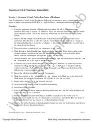
stimulus amplitude is increased. Change the stimulus amplitude (Amp) by increments of0.100V until the compound action potential reaches a maximum level. Record and mark theCAPs at each new stimulus amplitude.7. From the amplitudes of the compound action potentials generated by different stimulusamplitudes, determine the stimulus amplitude that will deliver a mid-sized compound actionpotential that will be easy to measure. This CAP is designated the criterion to which thecompound action potentials generated by stimuli of different amplitudes and durations must bematched.8. Change the stimulus amplitude to the voltage that generates the criterion. Click the Applybutton to finalize this change.9. Click Record to stimulate the nerve. Type 0.1 msec, V in theMark box. Press the Enter key on the keyboard to attach this notation to the recording.10. Record the amplitude of the criterion CAP, and the amplitude and duration of the stimulus pulseused to generate the criterion CAP in the Journal.11. Determine the stimulus amplitudes needed for each of the durations listed to produce acompound action potential with the amplitude of the criterion CAP. The stimulus durations tobe used are:5, 2, 1, 0.5, 0.2, and 0.05 msec.12. Change the stimulus duration to 5 msec and the stimulus amplitude to 0.100V. Click the Applybutton to finalize this change.13. Click Record to stimulate the nerve. Type 5 msec, 0.100V in the Mark box. Press the Enter keyon the keyboard to attach this notation to the recording.14. If the amplitude of the CAP is more than the amplitude of the criterion CAP, decrease thestimulus amplitude. If the amplitude of the CAP is less than that of the criterion, increase thestimulus amplitude. After changing the stimulus amplitude, click the Apply button to finalizethe change.15. Stimulate the nerve with different stimulus amplitudes until the amplitude that causes thecriterion response is found. Record the stimulus amplitude needed for the stimulus duration of 5msec in the Journal.Note: If the stimulus duration is longer, the stimulus amplitude needed to create the criterion is usuallysmaller.16. Repeat Steps 12 through 15 for each of the other stimulus durations.17. Select Save in the File menu.Exercise 7: Bidirectionality<strong>iWorx</strong> Sample LabAim: To determine if action potentials can travel in either direction in a nerve, and if they can, is there adifference in the conduction velocity in one direction compared to the other direction.Animal Nerve – <strong>Compound</strong> <strong>Action</strong> Potential – Labs<strong>AN</strong>-2-8Copyright <strong>iWorx</strong> Systems Inc.Note: Only for evaluation by prospective customers.
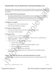
Procedure1. Reverse the positions of the lead wires attached to the electrodes of the nerve bath chamber. Putthe lead wires of the stimulator on the distal end of the nerve where the recordings were made inthe other exercises. Put the lead wires of the recording input on the proximal end of the nervewhere the stimulus was delivered in the other exercises. Put the lead wire for the ground on anelectrode between the stimulating and recording electrodes.2. If necessary, lower the level of Ringer’s solution in the nerve bath chamber below the nerve andblot any drops of solution from the preparation as described in Exercise 1.3. Adjust the stimulus duration (W) to 0.1 msec. Adjust the stimulus amplitude (Amp) to thevoltage used to generate the criterion CAP at a duration of 0.1 msec. Click the Apply button tofinalize the changes to these stimulus parameters.4. Use the same procedures used in Exercises 3 and 4 to measure the conduction velocity of thecompound action potential, if one is generated.Data AnalysisExercise 2-Stimulus and Response1. Use the Sweep Selection bar at the bottom of the Main window (Figure <strong>AN</strong>-2-L5) to display thefirst sweep recorded in Exercise 2. Click on the tab on the selection bar for that sweep and thesweep will appear on the Main window. According to the design of the exercise, the stimulusdelivered to the nerve in this sweep had an amplitude of 0.000V. Therefore, a compound actionpotential (CAP) should not appear on the sweep.Figure <strong>AN</strong>-2-L5: The Sweep Selection bar showing the tab for Sweep 7 highlighted.2. To display the second sweep recorded in this exercise, click on the tab on the selection bar forthat sweep. The stimulus delivered to the nerve in this sweep had an amplitude of 0.050V. Clickthe AutoScale button of the <strong>Compound</strong> <strong>Action</strong> Potential channel to maximize the size of acompound action potential and determine if a CAP occurred.3. If a CAP does not appear on the second sweep of this exercise, display the next sweep insuccession. Continue to move to the next sweep in succession until the sweep that displays thefirst appearance of a compound action potential is found.4. Once the sweep displaying the first CAP is found, transfer that sweep to the Analysis window.Click on the Analysis window icon in the toolbar or select Analysis from the Windows menu totransfer the sweep from the Main window to the Analysis window (Figure <strong>AN</strong>-2-L6).<strong>iWorx</strong> Sample LabAnimal Nerve – <strong>Compound</strong> <strong>Action</strong> Potential – Labs<strong>AN</strong>-2-9Copyright <strong>iWorx</strong> Systems Inc.Note: Only for evaluation by prospective customers.
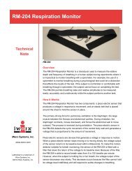
Figure <strong>AN</strong>-2-L6: <strong>Compound</strong> action potential (CAP) and stimulus pulse displayed in the Analysiswindow, with cursors positioned to measure the amplitude of the CAP.5. Look at the Function Table that is above the uppermost channel displayed in the Analysiswindow. The mathematical functions, V2-V1 and T2-T1 should appear in this table. The valuesfor V2-V1 and T2-T1 on each channel are seen in the table across the top margin of eachchannel.6. Maximize the height of the trace on the <strong>Compound</strong> <strong>Action</strong> Potential channel by clicking on thearrow to the left of the title of that channel to open the channel menu. Select Scale from themenu and AutoScale from the Scale submenu to increase the height of the data on that channel.7. Once the cursors are placed in the correct positions for determining the amplitude of thecompound action potential, the amplitude (V2-V1) can be recorded in the on-line notebook ofLabScribe by typing its name and value directly into the Journal, or on a separate data table.8. The functions in the channel pull-down menus of the Analysis window can also be used to enterthe name and value of the parameter from the recording to the Journal. To use these functions:• Place the cursors at the locations used to measure the amplitude of the compound actionpotential.• Transfer the names of the mathematical functions used to determine the amplitude to theJournal using the Add Title to Journal function in the <strong>Compound</strong> <strong>Action</strong> PotentialChannel pull-down menu.• Transfer the values for the amplitude to the Journal using the Add Ch. Data to Journalfunction in the <strong>Compound</strong> <strong>Action</strong> Potential Channel pull-down menu.9. To measure the amplitude of a compound action potential, place one cursor on the baselinebefore the stimulus artifact displayed on the <strong>Compound</strong> <strong>Action</strong> Potential Channel. Place theother cursor on the peak of the CAP (Figure <strong>AN</strong>-2-L6). The value for the V2-V1 function on the<strong>Compound</strong> <strong>Action</strong> Potential Channel is the amplitude of the compound action potential.<strong>iWorx</strong> Sample LabAnimal Nerve – <strong>Compound</strong> <strong>Action</strong> Potential – Labs<strong>AN</strong>-2-10Copyright <strong>iWorx</strong> Systems Inc.Note: Only for evaluation by prospective customers.
10. Record the amplitude and the stimulus amplitude used to generate the CAP in the Journal usingthe one of the techniques described in Steps 7 or 8, and on Table <strong>AN</strong>-2-L3.Table <strong>AN</strong>-2-L3: Amplitude and Times of <strong>Action</strong> <strong>Potentials</strong> Generated by Stimulus Pulses ofDifferent Amplitudes.Stimulus Amplitude (V)<strong>Compound</strong> <strong>Action</strong> <strong>Potentials</strong>Amplitude (mV)0.000 00.0500.1000.1500.2000.2500.3000.3500.4000.4500.50011. To display the compound action potentials recorded on other sweeps, click on the tabs for thosesweeps in the Sweep Selection bar at the bottom of the Analysis window. The sweeps that areselected will appear together on the Analysis window. Each successive sweep should have acompound action potential with a greater amplitude since the stimulus amplitude was increasedin each successive sweep. The compound action potential will reach a maximum amplitudewhen all the fibers in the nerve are firing. The amplitude of the compound action potential willnot increase even if a stimulus with a higher amplitude is applied to the nerve.12. To take measurements from another sweep displayed on the Analysis window, select its namefrom the Sweep menu in the upper left margin of the data display window (Figure <strong>AN</strong>-2-L7).Repeat Steps 9 and 10 to measure and record the amplitude of the CAP.13. Measure and record the amplitudes of all the compound action potentials from threshold tomaximum level.14. Select Save in the File menu.15. Click on the Main Window icon to return to that window.<strong>iWorx</strong> Sample Lab16. Graph the amplitude of the compound action potential as a function of the stimulus amplitude.Animal Nerve – <strong>Compound</strong> <strong>Action</strong> Potential – Labs<strong>AN</strong>-2-11Copyright <strong>iWorx</strong> Systems Inc.Note: Only for evaluation by prospective customers.
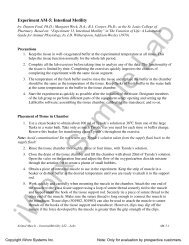
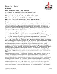
Figure <strong>AN</strong>-2-L7: The upper left corner of the Analysis window showing the Sweep menu used to selectthe sweep from which the data is measured.Questions1. Does the action potential in a single axon increase in amplitude when the stimulus amplitude isincreased?2. Does the amplitude of the CAP increase because more fibers are firing, or the amplitude of theaction potentials from single fibers are increasing, or a combination of both?3. How many fiber types did you observe in your monophasic recording of compound actionpotentials?4. The first peak of the compound action potential is composed of the responses of the Aα fibers.How does the threshold and diameter of these fibers compare to Aβ, Aγ, Aδ and C fibers?Exercise 3-Conduction Velocity1. Use the Sweep Selection bar at the bottom of the Main window to display the first sweepneeded to calculate the conduction velocity of the nerve. Click on the tab of that sweep and itwill appear on the Main window.2. Transfer the sweep to the Analysis window using the Analysis window icon in the toolbar or theAnalysis listing on the Windows menu.3. Display the second sweep needed to calculate the conduction velocity by clicking on its tab inthe Sweep Selection bar at the bottom of the Analysis window.4. Measure the time between the peaks of the two compound action potentials displayed on theAnalysis Window:• Place one cursor on the peak of the compound action potential in the first sweep.• Place the second cursor on the peak on the compound action potential in the secondsweep.• The value for T2-T1 on the <strong>Compound</strong> <strong>Action</strong> Potential Channel is the time it takes theCAP to move the distance between the two positions of the negative recording electrodeused in this exercise.• Record the value for T2-T1 (in msec) in the Journal, and on Table <strong>AN</strong>-2-L4, fortemperature and direction labeled as Room-Normal.<strong>iWorx</strong> Sample LabAnimal Nerve – <strong>Compound</strong> <strong>Action</strong> Potential – Labs<strong>AN</strong>-2-12Copyright <strong>iWorx</strong> Systems Inc.Note: Only for evaluation by prospective customers.
5. Measure the conduction distance (in mm) between the two positions of the negative recordingelectrode. Record this distance (in mm) in the Journal, and on the table, as the conductiondistance for temperature and direction labeled as Room-Normal.6. Calculate the conduction velocity (in meters per second). Divide the distance (in mm) betweenthe two positions of the negative recording electrode by T2-T1, which is the time (in msec)between the peaks of the two compound action potentials.For example, 10 mm/0.2 msec = 50 mm/msec = 50 m/sec7. Record the conduction velocity in the Journal, and on the table, for the temperature anddirection labeled as Room-Normal.8. Select Save in the File menu.Table <strong>AN</strong>-2-L4: Conduction Velocities of a Nerve at Two Different Temperatures.Temperature/DirectionRoom-NormalCold-NormalRoom-OppositeConduction Distance (mm) Time (msec) Conduction Velocity (m/sec)Exercise 4-Conduction Velocity at Low Temperature1. Use the same techniques used in the analysis of Exercise 3 to take measurements from the datain Exercise 4.2. Use the same techniques used in Exercises 2 and 3 to record the measurements from thisexercise in the Journal, and on Table <strong>AN</strong>-2-L4 for temperature and direction labeled as Cold-Normal.3. Calculate and record the conduction velocity of the nerve at a low temperature in the Journal,and on the table for temperature and direction labeled as Cold-Normal.4. Select Save in the File menu.Questions1. Does the conduction velocity change when the nerve is cooled?2. What properties of the ion channels may change with temperature?<strong>iWorx</strong> Sample LabAnimal Nerve – <strong>Compound</strong> <strong>Action</strong> Potential – Labs<strong>AN</strong>-2-13Copyright <strong>iWorx</strong> Systems Inc.Note: Only for evaluation by prospective customers.
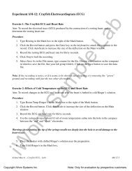
Exercise 5-Refractory Period1. Use the Sweep Selection bar at the bottom of the Main window to display the first sweep usedto demonstrate the refractoriness of the nerve. Click on the tab of that sweep and it will appearon the Main window. According to the design of the exercise for this sweep, two stimuluspulses are delivered to the nerve at an interval of 10 msec.2. Transfer the sweep to the Analysis window using the Analysis window icon in the toolbar or theAnalysis listing on the Windows menu.3. Measure the amplitude of the first compound action potential in the pair:• Place one cursor on the baseline before the stimulus artifact displayed on the <strong>Compound</strong><strong>Action</strong> Potential Channel.• Place the other cursor on the peak of the CAP.• The value for the V2-V1 function on the <strong>Compound</strong> <strong>Action</strong> Potential Channel is theamplitude of the compound action potential. Record this value in the Journal, and onTable <strong>AN</strong>-2-L5.Figure <strong>AN</strong>-2-L8: Pair of compound action potentials stimulated by a pair of pulses that are 5 msecapart.4. Repeat Step 3 for the second CAP in the pair.5. To display the compound action potentials recorded on other sweeps where the intervalsbetween the stimulus pulses are getting shorter, click on the tabs for those sweeps in the SweepSelection bar at the bottom of the Analysis window. The sweeps that are selected will appeartogether on the Analysis window.6. To take measurements from another sweep displayed on the Analysis window, select its namefrom the Sweep menu in the upper left margin of the data display window. Repeat Steps 3 and 4to measure and record the amplitude of the CAP.<strong>iWorx</strong> Sample LabAnimal Nerve – <strong>Compound</strong> <strong>Action</strong> Potential – Labs<strong>AN</strong>-2-14Copyright <strong>iWorx</strong> Systems Inc.Note: Only for evaluation by prospective customers.
7. Select Save in the File menu.Questions1. Does the first CAP in the pair have the same amplitude at all of the frequencies?2. Does the second CAP in the pair have the same amplitude at all of the frequencies?3. At which frequency, or interpulse interval, does the second CAP in the pair start to decline?4. What causes the change in the amplitude of the second CAP at some stimulus frequencies?5. What could be done to increase the amplitude of the second CAP if it declined?6. Is an axon that responds to a stimulus of increased amplitude in the absolute or relative portionof its refractory period?Table <strong>AN</strong>-2-L5: Amplitudes of <strong>Compound</strong> <strong>Action</strong> <strong>Potentials</strong> Occurring at Different Frequencies.Interpulse Interval (ms)Effective Frequency (Hz)10 1009 1118 1257 1436 1675 2004 2503 3332 5001 1000Exercise 6-Stimulus Strength-DurationAmplitudes (mV)First CAPSecond CAP1. Graph the stimulus amplitude needed to create the criterion CAP as a function of the stimulusduration.<strong>iWorx</strong> Sample Lab2. Place the values for the stimulus amplitudes on the Y-axis, and the values for the stimulusdurations on the X-axis.Animal Nerve – <strong>Compound</strong> <strong>Action</strong> Potential – Labs<strong>AN</strong>-2-15Copyright <strong>iWorx</strong> Systems Inc.Note: Only for evaluation by prospective customers.
3. The minimum stimulus amplitude which will elicit action potentials at an infinitely longstimulus duration is a value known as the rheobase. Another value, chronaxie, is the stimulusduration where the stimulus amplitude is twice the value of the rheobase. Chronaxie values areused as measures of the excitability of nerves. The most excitable nerves have the smallestchronaxies. Using the graph created in Step 1, determine rheobase and chronaxie for the nervein your chamber.Questions1. How does the excitability of your nerve compare to the nerves used by other groups in your labsection?2. Collect conduction velocity and chronaxie data from the other groups in your lab section. Isthere a relationship between conduction velocity and nerve excitability? If so, what is it?Exercise 7-Bidirectionality1. Use the same techniques used in the analysis of Exercise 3 to take measurements from the datain Exercise 7.2. Use the same techniques used in Exercises 2 and 3 to record the measurements from thisexercise in the Journal, and on Table <strong>AN</strong>-2-L4 for temperature and direction labeled as Room-Opposite.3. Calculate and record the conduction velocity of the nerve at room temperature and in theopposite direction in the Journal, and on the table for temperature and direction labeled asRoom-Opposite.4. Select Save in the File menu.Questions1. Do you record an action potential from the proximal end of the nerve?2. What is the conduction velocity for the nerve when stimulated in reverse direction? Is thissimilar to the value recorded when the nerve was stimulated from the proximal end to the distalend?3. How can an axon conduct action potentials in both directions?Note: Where are the cell bodies and synapses in this preparation?<strong>iWorx</strong> Sample LabAnimal Nerve – <strong>Compound</strong> <strong>Action</strong> Potential – Labs<strong>AN</strong>-2-16Copyright <strong>iWorx</strong> Systems Inc.Note: Only for evaluation by prospective customers.
AppendixRecipe for Amphibian Ringer’s Solution.Concentration (mMolar) Salt Grams/Liter DI H 20111.0 Sodium Chloride 6.491.9 Potassium Chloride 0.1421.06 Calcium Chloride∗2H 2O 0.1561.0 Tris 0.1215.55 Glucose 1.000Adjust the pH of the solution to 7.6 with 6N HCl<strong>iWorx</strong> Sample LabAnimal Nerve – <strong>Compound</strong> <strong>Action</strong> Potential – Labs<strong>AN</strong>-2-17Copyright <strong>iWorx</strong> Systems Inc.Note: Only for evaluation by prospective customers.