MW24F8 - Code Mercenaries
MW24F8 - Code Mercenaries
MW24F8 - Code Mercenaries

Create successful ePaper yourself
Turn your PDF publications into a flip-book with our unique Google optimized e-Paper software.
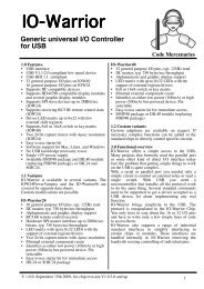
<strong>MW24F8</strong>3D acceleration sensorfor mouse input<strong>Code</strong> <strong>Mercenaries</strong>1. Features• USB interface (low speed)• Full USB V1.1/2.0 compliance• Full USB HID 1.1 compliance• 3 axis acceleration sensor• Mouse movement controlled by tilt angle oracceleration• Scrolling by gesture detection (verticalmovement)• Jumper selectable range• Button selectable scrolling option• Up to 6 buttons supported• Single +5V power supply• Available as completely assembled ready to usemodule or as a USB interface chip in 24 pinSOIC package (not including the sensorelement)1.1 VariantsMouseWarrior24F8 is available as either acompletely assembled module including theMEMS sensor, or as just the USB interface chip inSOIC24 package. The interface chip does notinclude the sensor. The option to buy the interfacechip separately is intended for volume productionwhere a tighter integration with the target device isrequired.2. Functional overviewMouseWarrior24F8 uses a MEMS solid state 3 axisacceleration sensor for acceleration or inclinationsensing. The X and Y axes are converted intomouse movement data.This allows to build a completely sealed mousesensor as no external moving parts are required andno special electrical or mechanical properties needto be observed to allow proper sensor operation.The Z axis may be used for scrolling, or the Y axiscan be used for scrolling when a designated buttonis pressed.2.1 ScrollingVertical scrolling can be done by gesture detection.The Z axis is used in combination with X and Y todetect purely vertical movement.If a purely vertical movement is detected thisinformation is used to generate scroll data. Theinitial direction of the movement is used to detectthe intended direction of scrolling.It takes a little practice to properly use this functionand it works best if the device in which <strong>MW24F8</strong>is embedded is used while standing, rather thansitting in front of the computer screen.1.2 Custom variantsCustom adaptions are available on request.Customization may be subject to minimum ordervolumes.V 1.0.0, August 12th 2008 for Chip Revision V1.0.3.81
<strong>MW24F8</strong><strong>Code</strong> <strong>Mercenaries</strong>3.0 Pin configurationsMouseWarrior24F8-S24 Pin SOICDrawing: TOP VIEW!/FLIP 124 /SSRANGE/CENTER232322MOSIMISOINTB0452120SCKB1B2 619 B3B4NC781817B5/ScrollGND 916 D+PullToGND 1015 D-VREG 1114 VccZ 12 13 NCMouseWarrior24F8-MODModuleDrawing: BOTTOM VIEW! (Components on the other side)V 1.0.0, August 12th 2008 for Chip Revision V1.0.3.82
<strong>MW24F8</strong><strong>Code</strong> <strong>Mercenaries</strong>3.1 Axis orientation for MouseWarrior24F8-MODStandard orientation if /FLIP is not pulled lowV 1.0.0, August 12th 2008 for Chip Revision V1.0.3.83
<strong>MW24F8</strong><strong>Code</strong> <strong>Mercenaries</strong>3.2 Jumper positions for MouseWarrior24F8-MODV 1.0.0, August 12th 2008 for Chip Revision V1.0.3.84
<strong>MW24F8</strong><strong>Code</strong> <strong>Mercenaries</strong>4.0 Pin descriptions MouseWarrior24F8-SName I/O Type Pins DescriptionD+, D-B0, B1, B2,B3, B4, B5I/OIspecialinput, internal Pull Up16,155, 20, 6, 19, 7, 18Z/FLIPRANGE/CENTER/SCROLLINTSCKMISOMOSI/SSVREGPullToGNDGNDVccNCIIIIIIOIOOOIinput, internal PullDowninput, internal Pull Upinput, internal Pull Upinput, internal Pull Upinput, internal Pull Uphigh impedanceexternal level shift *high impedanceexternal level shift *open drainspecial **Power supplyPower supply*) Level adaption to the 3.3V supply of the MEMS sensor is required.**) See application circuit for detailsUSB differential data linesButton inputs, active low12Pull high to disable Z axis from being used forscroll function1Pull low to use module in head down position23Pull low to reduce active sensing range to 25%Pull low to disable the dynamic recentering17Pull low to use Y axis for scrolling function4INT signal from MEMS sensor21SCK to MEMS sensor, level adaption required22SDO from MEMS sensor23SDI to MEMS sensor, level adaption required24CSB signal to MEMS sensor11Power for USB D- pull up resistor10Used during manufacturing, connect to GND9Ground14Supply voltage8, 13 do not connect4.1 Pin descriptions MouseWarrior24F8-MODName I/O Type DescriptionD+, D-B0, B1, B2,B3, B4, B5I/OIspecialinput, internal Pull UpB7GNDVccIinput, internal Pull UpPower supplyPower supplyUSB differential data linesButton inputs, active low/SCROLL inputGroundUSB supply voltageV 1.0.0, August 12th 2008 for Chip Revision V1.0.3.85
<strong>MW24F8</strong><strong>Code</strong> <strong>Mercenaries</strong>4.2 Pin descriptions: SOIC24 packageD+, D-Differential data lines of USB. Connect thesesignals direct to a USB cable. D- requires a pull upresistor, see application circuit for details.B0..B5Inputs for the buttons. Connect contacts closing toground.Internal pull up resistors.VREGSupplies 3.3V for the USB D- pull up resistor.Don't use this pin to supply power to externalcircuitry, it does only supply sufficient current forthe pull up resistor.INTInput for the INT signal from the MEMS sensor.This input is used to trigger a wakeup.High impedance input, connect direct to MEMSsensor.SCKSCK output to the MEMS sensor.External level adaption to the 3.3V supply of thesensor is required. See application circuit fordetails.MISOData input from the MEMS sensor.High impedance input, connect direct to SDO ofthe sensor./FLIPPull low to enable head down operation. Thisinverts the direction of X and compensates thenegative g force on Z.Internal pull up resistor.RANGEPull low to reduce the tilt range used for the mousecursor control. This allows to use the sensor withsmaller maximum angles and prevents theautocalibration function from getting offset byacceleration overshoots.Internal pull up resistor./CENTERPulling this pin low disables the automaticrecentering.Internal pull up resistor./SCROLLMay be used with a button to activate using the Yaxis for scrolling. When pulled low X and Ymovement will be suppressed and the Y axis datais used for scrolling.Internal pull up resistor.NCDo not connect, pin may be used in future variants.GNDPower supply ground.VccSupply voltage.MOSIData output to the MEMS sensor.External level adaption to the 3.3V supply of thesensor is required. See application circuit fordetails./SSEnable output to the MEMS sensor.Open drain output, connect direct to CSB of thesensor.ZOption to disable the use of the Z axis for scrolling.Pull high to disable scrolling by Z axis.Internal pull down resistor.V 1.0.0, August 12th 2008 for Chip Revision V1.0.3.86
<strong>MW24F8</strong><strong>Code</strong> <strong>Mercenaries</strong>4.3 Pin descriptions: ModuleD+, D-, Vcc, GNDConnect to a USB cable with a type A plug on itsother end.B0..B5Inputs for the buttons. Connect contacts closing toground.Internal pull up resistors.B7Input for /SCROLL option.4.4 Jumper descriptions: ModuleJ1 - Z option, close to disable Z axis for scrolling.5. Device operationMouseWarrior24F8 works as a standard USBmouse with six buttons and a scroll function. Nospecial drivers need to be installed, it is compatiblewith the default system drivers.5.1 Low level sensor accessIn addition to the mouse function it is possible todirectly access the acceleration sensor ofMouseWarrior24F8.The interface for accessing the sensor data isidentical to that of the JoyWarrior24F8. The toolsfor JoyWarrior24F8 do work withMouseWarrior24F8 as well.Please refer to the JoyWarrior24F8 data sheet for adetailed description of direct access to the sensor.J2 - /Flip option, close to use the module in headdown position.J3 - RANGE option, close to reduce the sensorrange if the mechanics allows only a limited tiltangle.J4 - /CENTER option, close to disable theautomatic recentering.V 1.0.0, August 12th 2008 for Chip Revision V1.0.3.87
<strong>MW24F8</strong><strong>Code</strong> <strong>Mercenaries</strong>6. DC Characteristics <strong>MW24F8</strong>-S / <strong>MW24F8</strong>-MODV ccI ccI sbI sbR upV ithV ohV olV diV cmV seC inI ioR puR pdParameter Min Max Units RemarksOperating Voltage4.35 5.25 VOperating Supply Current20 mASuspend mode current (chip)25 µA Oscillator offSuspend mode current (module)350 µA Sensor workingPull-up Resistance8 24 kΩInput Threshold Voltage40% 60% VccUSB InterfaceStatic output high 2.8Static output lowDifferential Input sensitivity 0.2Differential Input common Mode Range 0.8Single Ended Transceiver Threshold0.8Transceiver capacitanceHi-Z State Data Line Leakage -10Bus Pull-up resistanceBus Pull-down resístance1.27414.253.6 V 15kΩ±5% to GND0.3 VV |(D+)-(D-)|2.52.0VV2010pFµA 0V < Vin < 3.3V, Hi-Z State1.32615.75kΩkΩ1.3kΩ±2% to Vreg15kΩ±5%6.1 AC Characteristics <strong>MW24F8</strong>-S / <strong>MW24F8</strong>-MODF iclk2t rt rt ft ft rfmV crst dratet djr1t djr2t deopt eopr1t eopr2t eoptt udj1t udj2Parameter Min Max Units RemarksInternal clock frequency5.91 6.09 MHz Clock synchronized to USBUSB Driver CharacteristicsTransition rise time75ns CLoad = 50pFTransition rise time300 ns CLoad = 350pFTransition fall time75ns CLoad = 50pFTransition fall time300 ns CLoad = 350pFRise/Fall Time matching80 125 %Output signal crossover voltage1.3 2.0 VUSB Data TimingLow Speed Data Rate 1.4775 1.5225 MBit/sReceiver data jitter tolerance-75 75 ns To next transitionReceiver data jitter tolerance-45 45 ns For paired transitionsDifferential to EOP transition skew-40 100 nsEOP width at receiver165ns Rejects as EOPEOP width at receiver675ns Accepts as EOPSource EOP width1.25 1.50 µsDifferential driver jitter-95 95 ns To next transitionDifferential driver jitter-150 150 ns To paired transitionV 1.0.0, August 12th 2008 for Chip Revision V1.0.3.88
<strong>MW24F8</strong><strong>Code</strong> <strong>Mercenaries</strong>6.2 Absolute maximum ratingsStorage Temperature-50°C to +150°CAmbient Operating Temperature0°C to +70°CSupply Voltage on VCC relative to VSS-0.5V to +7.0VDC Input Voltage -0.5V + VCC + 0.5VMax. Output Current into any Pin60mAPower Dissipation300mWStatic Discharge Voltage (USB and button inputs) >2000VLatch-up Current>200mAEEPROM write cycles (same byte)≥1000EEPROM data retention (at 55°C after 1000 cycles)≥10 yearsMechanical Shock *10,000g, ≤100µs2,000g, ≤1msFree fall onto hard surface *≤1.5m*) Maximum shock specs apply for the sensor element only. Using the module in high-g environmentswill require additional mechanical protection.6.3 Sensor characteristics (<strong>MW24F8</strong>-MOD)Parameter Min Typ Max UnitsS 2gS 4gAcceleration resoultion at ±2gAcceleration resoultion at ±4g246122256128266134LSB/gLSB/gS 8gOffAcceleration resoultion at ±8gZero-g Offset at T A = 25°C61-6064 6760LSB/gmgOff Zero-g Offset over lifetime, T A = 25°CZero-g Offset temperature drift-1501150 mgmg/KNL Nonlinearity-0.5%0.5% %FSn rms/SOutput NoiseCross Axis Sensitivity, relative between axes0.52mg*√f (filter bandwith)%V 1.0.0, August 12th 2008 for Chip Revision V1.0.3.89
<strong>MW24F8</strong><strong>Code</strong> <strong>Mercenaries</strong>7. Ordering informationPartname Order <strong>Code</strong> Description PackageMouseWarrior24 F8 <strong>MW24F8</strong>-MOD 3D acceleration sensor based mouse complete module ModuleMouseWarrior24 F8 <strong>MW24F8</strong>-S 3D acceleration sensor based mouse interface chipSOIC24The chips listed here are standard products.Customized chips are available on request.7.1 Packaging infoSOIC24 chips come in tubes with 31 chips each.To assure best handling and shipping safety pleaseorder the chips in full tubes. Custom chips areproduced in multiples of full tubes only.<strong>MW24F8</strong>-MOD modules come in antistatic boxesor antistatic bags packaged single or bulk.7.2 USB VendorID and ProductIDBy default all MouseWarrior chips are shippedwith the USB VendorID of <strong>Code</strong> <strong>Mercenaries</strong>($7C0 or decimal 1984) and a fixed ProductID.On request chips can be equipped with thecustomers VendorID and ProductID. VendorIDscan be obtained from the USB ImplementersForum Customized chips are subject to minimum orderquantities, contact fordetails.Following are the ProductIDs for theMouseWarrior controllers:MouseWarrior24 F8 $1114ProductIDs are independent of the package type.See the JoyWarrior data sheet for versioninformation.V 1.0.0, August 12th 2008 for Chip Revision V1.0.3.810
<strong>MW24F8</strong><strong>Code</strong> <strong>Mercenaries</strong>8. Typical application for MouseWarrior24 F8 (as used on the module)USB+5VD-D+GND1234C1100nFR11k3B0 B1 B2 B3 B4 B5Circuit:Version:Date:Drawn by:Function:Page:JoyWarrior 24F8V1.019.2.2008<strong>Code</strong> <strong>Mercenaries</strong>Rev. Date By Change Sign.67854SCKSDOSDICSBINTVDD VDDIOSMB380GNDNCNC11032913VinVenLP5951GndVoutNC54R210KT1R310KT2C2100nFC3100nF214J11312111516NCZVREGD-D+Vcc<strong>MW24F8</strong>PullToGNDVssSCKMISOMOSI/SSINTCenterRangeFlip/ScrollNCB5B4B3B2B1B02122232443211781871962053.3V109V 1.0.0, August 12th 2008 for Chip Revision V1.0.3.811
<strong>MW24F8</strong><strong>Code</strong> <strong>Mercenaries</strong>9. Package dimensions24 Pin SOICModuleAll dimensions in mmMounting holes 2.5mmV 1.0.0, August 12th 2008 for Chip Revision V1.0.3.812
<strong>MW24F8</strong><strong>Code</strong> <strong>Mercenaries</strong>10. ESD ConsiderationsMouseWarrior has an internal ESD protection towithstand discharges of more than 2000V withoutpermanent damage. However ESD may disruptnormal operation of the chip and cause it to exhibiterratic behaviour.For the typical office environment the 2000Vprotection is normally sufficient. Though forindustrial use additional measures may benecessary.When adding ESD protection to the signals specialcare must be taken on the USB signal lines. TheUSB has very low tolerance for additionalresistance or capacitance introduced on the USBdifferential signals.Series resistors of 27Ω may be used alone or inaddition to some kind of suppressor device. In anycase the USB 2.0 specification chapter 6 and 7should be read for detailed specification of theelectrical properties.10.1 EMC considerationsMouseWarrior uses relatively low power levels andso it causes few EMC problems.To avoid any EMC problems the following rulesshould followed:• Put the 100nF ceramic capacitor right next tothe power supply pins of the chip and make surethe PCB traces between the chips power pinsand the capacitor are as short as possible.• Run the power supply lines first to the capacitor,then to the chip.• Keep the two USB signal lines close to eachother, route no other signal between them. USBuses differential signalling so the best signalquality with lowest RF emission is achieved byputting these lines very close to each other.• Adding a ferrite bead to the +5V power supplyline is advisable.11. Revision historyPlease refer to the JoyWarrior main data sheet forthe revision history.Legal stuffThis document is ©1999-2008 by <strong>Code</strong><strong>Mercenaries</strong>.The information contained herein is subject tochange without notice. <strong>Code</strong> <strong>Mercenaries</strong> makesno claims as to the completeness or correctness ofthe information contained in this document.<strong>Code</strong> <strong>Mercenaries</strong> assumes no responsibility forthe use of any circuitry other than circuitryembodied in a <strong>Code</strong> <strong>Mercenaries</strong> product. Nordoes it convey or imply any license under patent orother rights.<strong>Code</strong> <strong>Mercenaries</strong> products may not be used in anymedical apparatus or other technical products thatare critical for the functioning of lifesaving orsupporting systems. We define these systems assuch that in the case of failure may lead to thedeath or injury of a person. Incorporation in such asystem requires the explicit written permission ofthe president of <strong>Code</strong> <strong>Mercenaries</strong>.Trademarks used in this document are properties oftheir respective owners.<strong>Code</strong> <strong>Mercenaries</strong>Hard- und Software GmbHKarl-Marx-Str. 147a12529 Schönefeld OT GrossziethenGermanyTel: x49-3379-20509-20Fax: x49-33790-20509-30Mail: support@codemercs.comWeb: www.codemercs.comHRB 16007 PGeschäftsführer: Guido Körber, Christian LuchtInitial shipping version of <strong>MW24F8</strong> is V1.0.3.8.V 1.0.0, August 12th 2008 for Chip Revision V1.0.3.813