D - Avant-Garde Engineering
D - Avant-Garde Engineering
D - Avant-Garde Engineering

Create successful ePaper yourself
Turn your PDF publications into a flip-book with our unique Google optimized e-Paper software.
P.E. Civil Exam Review:Structural t DesignJ.P. MohsenEmail:jpm@louisville.edu
Ultimate strengthYield pointRuptureStressElastic limitProportional limit∆σ∆εStrainStress Strain DiagramSlide2
InitialtangentmodulusTangentmodulusChordmodulusStressSecantmodulusStrainMethods for approximating modulus of ElasticitySlide3
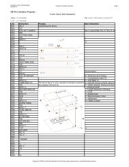
CALCULATING THE ELASTIC MODULIσ ULT = 3600 psi; 40% σ ULT = 1440 psi = SOT 1Secant Modulus: Slope of the linecorresponding to stress SO =1440/(400x10 -6 ) = 3.6 x 10 6 psi4000Chord Modulus: Slope of the linecorresponding to stress SC = (1440-200)/(400-50) x 10 -6 = 3.5 x 10 6 psiStress s, psi30002000s1000DT0.68 water/cement ratio,6x12 in. concrete cylinder(3000 psi designed strength),standard cured for 28 days.Tangent Modulus: Slope of the line TT 1drawn tangent to any point on the σ-εcurve = 2.5 x 10⁻⁶ psiDynamic Modulus(Initial Tangent Modulus): Slope of theOD from the origin = 1000/200 = 5 x 10 6psicO 50 500 1000 1500 2000 2500Strain, x 10 -6Different types of elastic moduli and the method by which these aredetermined for Portland Cement ConcreteSlide4
Slide5
P.E. Review Course : ConcreteStress-Strain Curve :• Linear from zero to 0.4 fc’• Beyond this range non-linear• Ult. Strength @ strain of 0.002”/”• Strain @ Rupture 0.003-0.004 “/”• @ Low fc’ Strain @ Rupt. 0.004 004 ”/”• @ High fc’ Strain @ Rupt.
P.E. Review Course : ConcreteModulus of Elasticity :•Tangent Modulus –tangent @ 0.5 fc’1.5•ACI : E = 33 (fc’) ) w^1.5,for 90 to 155 pcf concrete•ACI : E = 57000 (fc’),wfor 145 pcf concreteSlide7
P.E. Review Course : ConcreteFlexural Behavior of Concrete• As the load is applied, the beamundergoes three distinct stagesbefore Collapse• (a) Uncracked• (b) Cracked – Elastic Stage• (c) Ultimate Strength StageSlide8
Slide9
Slide10
P.E. Review Course : ConcreteCracking Moment :•From flexure formula : f = M y / Ig•Cracking Moment = Momentwhen f = fr ; & fr = 7.5 fc’ fornormal wt. conc., where fc’ in psi•Hence, M Mcr = fr I Ig / ytSlide11
P.E. Review Course : ConcreteReinforcing Steel :Deformed bar sizes range from#3 to #18.• Up to #8, bar diameter in eighths• Area of #9,#10,#11 corresponds toarea of 1”, 1 1/8” & 1 1/4 ” squares Slide12
Problem 1(a) Assuming the concrete is uncracked, compute the bending stresses in theextreme fibers of the beam for a bending moment of 25 ft-k. The concretehas an f’ c of 4000 psi and a modulus of rupture f r = 7.5*(4000) 0.5 = 474 psi(b) Determine the cracking moment of the sectionf’ ccβ 1 c= a0.85f’ cC = 0.85f’ c abdd – a/2A sf yT = A s f yb(a) Beam(b) Actual compressionstress variation(c) Assumed compressionstress variationSlide13
Problem 1 (continued)(a)Bending stresses:gM yf II g 1 1234 12 18 5832in.3#9(A s = 3.00 in 2 )15”3”12 18” 25,000 9.00f 463psi583212”Since this stress is less than the tensile strength or modulus of rupture of the concrete of 474psi, the section is assumed not to have cracked.(b) Cracking moment:M4745832frIg 307,152in lb 25. 6y 9.00cr6tft kSlide14
P.E. Review Course : ConcreteTheoretical Moment :Tensile force T = As • fyCompressive Force C = 0.85 fc’ a b,• a = depth of stress block &• b = width of beam• C = T ; As * fy = 0.85 fc’ a b• a = As * fy /( 0.85 fc’ b )• Moment arm = d – 05 0.5 * aSlide15
P.E. Review Course : ConcreteCharles Whitney’s Theory (Contd):• Per ACI (10.2.7.3) (10273) 1 = 0.85 forfc’ 4000 psi.• For fc’ > 4000 psi :1 = 0.85 – 0.05 (fc’-4000)/1000• 1 shall be 0.65Slide16
Problem 3Determine M n the nominal moment or theoretical ultimate moment strength ofthe beam section shown if f y = 60,000 psi and f’ c = 3000 psi.yc0.85f’ caCd = 21”24”d – a/23#9(A s = 3.00 in 2 )A s3”Tb = 14”Slide17
P.E. Review Course : ConcreteTheoretical Moment :• Nom. Moment Mn = T * (d – 05 0.5 * a )• = C * (d – 0.5 * a )• Mn = As * fy * (d – 05 0.5 * a ) or• Mn = 0.85 fc’ a b * (d – 0.5 * a )Slide18
Problem 3 (continued)Compression and tension couple at nominal moment.f’ ccβ 1 c= a0.85f’ cC = 0.85f’ c abdd – a/2A sf yT = A s f yb(a) Beam(b) Actual compressionstress variation(c) Assumed compressionstress variationSlide19
Problem 3 (continued)Computing Tensile and Compressive Forces T & C.TCAsfy0.85 f abc3.0060180k 0.853a1435.7a0.85f’ caCd = 21”24”d – a/23#9(A s = 3.00 in 2 )A s3”Tb = 14”Slide20
Problem 3 (continued)Equating T and C and Solving for a.T C for180 35.7aa 5.04 inequilibrium0.85f’ caCd = 21”24”d – a/23#9(A s = 3.00 in 2 )A s3”Tb = 14”Slide21
Problem 3 (continued)Computing (d – a/2) and M na 5.04d 2118.48in2 2M n2 180 18.48 3326.4in k 277.2ft k0.85f’ caCd = 21”24”d – a/23#9(A s = 3.00 in 2 )A s3”Tb = 14”Slide22
P.E. Review Course : Concrete4Slide23
P.E. Review Course : ConcreteProblem # 4 : Stress/StrainDetermine values a, c & t for thebeam shown. fy =60000 psi & fc’=3000psiSolution :a = As fy/(0.85 fc’ b); =(2.37)(60)/(0.85 • 3 • 14) = 398” 3.981= 0.85 for 3000.0 psi concreteSlide24
P.E. Review Course : ConcreteProblem # 4 : (Contd.)c = a / 1 = 3.98/0.85 85 = 468” 4.68t = (d-c) (0.003)/c= (21.0-4.68)(0.003)/4.68 =0.01046”/”End of ProblemSlide25
Problem # 4 (continued)nominal moment capacity:Mn = As fy (d- 0.5 a)=2.37 x 60000.0 x (21.0 – 0.5 x 3.98)= 2703.2222 in-k = 225.2727 ft-kSlide27
P.E. Review Course : ConcreteProblem # 4 : Moment Capacity (Cont.)What is the Ultimate Moment capacity?fy =60000 psi , fc’=3000 psi;Given:a = 3.98”, c = 4.68”, t = 0.01046”/”Solution :Ultimate Moment Capacity = Mn = 0.90 x 225.27 = 202.74 ft-kSlide28
P.E. Review Course : ConcreteStrength Reduction Factor :• Mu, Ult. Strength = Mn • Mn = Nominal Strength = Strength Reduction Factor• accounts for uncertainties inmaterial strength, dimensions andworkmanship• Usable flexural strength = Mn * • varies from 0 90 for beams to Slide29 varies from 0.90 for beams to0.65 for columns
P.E. Review Course : ConcreteStrength Reduction Factors :• = 0.90 for Tension ControlledBeams & Slabs• = 0.75 for Shear & Torsion• = 0.65 or 0.70 for Columns• = 0.65 or 0.70 or 0.90 for Columnw/ small axial loads• = 0.65 for Bearing on ConcreteSlide30
P.E. Review Course : ConcreteUltimate Moment Capacity :• Factored ultimate moment = Mu• Mu= Service Moment • Load Factor• Usable flexural Strength Mn • Mu• C = T• 0.85 fc’ a b = As * fy• a = As fy/(0.85 fc’ b); fy d/0.85 fc’where = As/(b d) = Ratio of steel toSlide31where As/(b d) Ratio of steel toconcrete
P.E. Review Course : ConcreteUltimate Moment Strength (Contd.):• Nom Mom Mn = T(d – 0.5a) = As fy (d-0.5 a)• Usable flex str = Mn = * As fy (d-0.5 a)• Mn = Mu (Required Ultimate Strength).• Substitute value of a,• a = fy d/0.85 fc’, the equn. becomes :• Mn = Mu = As fy d [1-( fy /1.7 fc’ )]Slide32
P.E. Review Course : ConcreteProblem # 5 : Beam Capacity AnalysisBeam shown spans 30.0’ andcarries a live load of 418.5 plf.Is the strength adequate?LL = 418.5 p/ft30ft• ACI 9-2 : U = 1.2 DL +1.6 LLSlide33
Problem 5P.E. Review Course : ConcreteSlide34
Problem 5 :LL = 418.5 lb/ft30 FtDL of beam = [0.833 x 1.5833] x 150 = 198.0 plfLL = 418.5 plfM at mid-point = w L 2 /8Wu = 1.2 x 198 + 1.6 x 418.5 = 907.2 plfM = 2 = 2 required Wu L /(8 ) 0.9072 x 30 /(8 X 0.9) =113.4 ft.kSlide35
P.E. Review Course : ConcreteProblem # 5: Beam Capacity Analysis (Contd.)Depth of stress blocka = As fy / 0.85 fc’ bw= 3 x 0.79 x 40000/(0.85 4000.0 0 10) = 2.79”M capacity = As fy y( (d – a/2) =3 x 0.79 x 40000 (16 – 2.79/2) =115.4 ft.k > 113.4 ft.k (O.K.)Slide36
P.E. Review Course : ConcreteDesign of Rectangular Beams & SlabsLoad Factors :• ACI 9-1 : U = 1.4 (D + F)• ACI 9-2 : U = 1.2 (D + F + T) +1.6 (L + H) +0.5 (Lr or S or R)• ACI 9-3 : U = 1.2 D + 1.6 (Lr or S or R) +(1.0 L or 0.8 W)• ACI 9-4 : U = 1.2 D + 1.6 W + 1.0 L + 0.5 (Lror S or R)Slide37
P.E. Review Course : ConcreteDesign of Rectangular Beams & SlabsLoad Factors : (Contd.)• ACI 9-5 : U = 1.2 D + 1.0 E + 1.0 L + 0.2 S• ACI 9-6 : U = 0.9 D + 1.6 W + 1.6 H• ACI 9-7 : U = 0.9 D + 1.0 E + 1.6 HSlide38
P.E. Review Course : ConcreteDesign of Rectangular Beams & Slabs (Contd.)Load Factors : Where,• U = The Ultimate Load on the StructuralElement• D = Dead Load; L = Live Load; F = Weightand Pressure of Fluids• T = Total Load from Temperature, Creep,Shrinkage, differential Settlement,Shrinkage-Compensating ConcreteSlide39
P.E. Review Course : ConcreteDesign of Rectangular Beams & Slabs (Contd.)Load Factors : Where,• H = Weight and Lateral Pressure from Soil,Groundwater pressure & Lateral Pressurefrom bulk materials• Lr = Roof Live Load; S = Snow Load; R =Rain Load; W = Wind Load• E = Seismic or Earthquake LoadsSlide40
P.E. Review Course : ConcreteProblem # 6 : Balanced Percentage of SteelDetermine the balanced steel ratio bfora reinforced concrete beam if fy =60,000psi ; fc’=3000 psi; Determine whether thebeam in Problem # 8 is tension controlled.Solution :b = ( 0.85 1 fc’/fy) [87000/(87000 + fy)](Assume /b/ b shall be 0.63 for tensioncontrolled failure)Slide41
P.E. Review Course : ConcreteSections Based on Failure :• Balanced Section : Concrete crushes and the steel yields at thesame time.• Per ACI, c = 0.003; s = 0.002 for 60 ksi steel• Tension Controlled : Per ACI 10.3.4, c 0.003; s 0.005, Steel hasyielded.• Compression Controlled : c = 0.003; s 0.002 , Concrete hascrushedSlide42
P.E. Review Course : ConcreteMinimum Percentage of Steel :• As,min = 3 bw d fc’ /fy• Also, As,min 200 bw d/fySlide43
P.E. Review Course : ConcreteProblem #6 : Balanced Percentage of Steel (Contd)1= 0.85 for 3000.0 psi concreteb = ( 0.85 x 0.85 x 3000/60000) [87000/(87000 +60000)]= 0.0213802138 = As/b d = 2.37/(14.0 x 21.0) = 0.0080600806/b = 0.00806/0.02138 = 0.377 < 0.63 … TensionControlsEnd of ProblemSlide44
P.E. Review Course : ConcreteOne Way Slabs :• Slabs are flat plates supported by beams, walls• If supported on two opposite sides, it is one way slab• Slab assumed to be rect. beam of 12” wide• Main reinf. placed perpendicular to supports• Max Spacing 3 X thickness or 18” (ACI 7.6.5)Slide45
P.E. Review Course : ConcreteOne Way Slabs : (Contd.)• Place shrinkage reinforcementperpendicular to main reinf.• Min. As = 0.002 b h for fy
P.E. Review Course : ConcreteSlide47
P.E. Review Course : ConcreteSlide48
ThirteenthEditionSCM - SteelConstructionManualASCE 360 -Specification forStructural t SteelBuildingsSlide49
MiscellaneousProperties of Geometric Sections – Table 17-27,Page 17-36SCM 13 th EditionCross-Reference TableManual of Steel Construction – LRFD-3 rd EditionTable 3-2 Table 5-3, Page 5-42Table 3-10 Beam Design Moments, Page 5-71Table 3-23 Table 5-17, Page 5-161Table C-C2.2CTable C-C2.1, C Page 16.1-189Table 4-1 Table 4-2, Page 4-21Table 4-22 Tables 3-36 (Page 16.1-143) and 3-50 (Page 16.1-145)Slide50Table 5-1 Table 3-1, Page 3-1750
Steel Construction ManualOrganization . . .• Part 1 – Dimensions and Properties• Part 2 – General Design Considerations• Part 3 – Design of Flexural l Members• Part 4 – Design of Compression Members• Part 5 – Design of Tension Members• Part 6 – Design of Members Subjected toCombined Loading51Slide51
. . . Steel ConstructionManual Organization• Part 7 – Design Considerations for Bolts• Part 8 – Design Considerations for Welds• Part 9 – Design of Connection Elements• Part 10 – Design of Simple ShearConnections. . .• Part 16 – Specifications and Codes52Slide52
Basic Design RequirementLRFDRu RnR u required strength capacity reduction factor nominal resistanceRnCalculation of Rnis identical for both methodologiesASDRnRa R aR nrequired strengthsafety factornominal resistance53Slide53
Structural SteelF – specified minimum yield stressyFu– specified minimum tensile strengthASTM A992F = 50 ksi; F = 65 ksiyuASTM A36ksi – kips per square in.1 k = 1000 lbFy= 36 ksi; Fu= 58 ksi54Slide54
SCM Part 1 – Dimensions and PropertiesSlide55
Table 1-1Slide56
WideflangePage 1-1818SCM(W)W18x40Nominal depth = 18 inWeight = 40 lb/ftArea=11.8 in2Actual depth = 17.9 in57Slide57
W Section Dimensions58Slide58
W Section Dimensions59Slide59
W Section Dimensions60Slide60
W Section propertiesStrong (x) axispropertiesSlide61
W Section propertiesMoment ofinertia IxSlide62
W Section propertiesRadius ofgyration rxSlide63
W Section propertiesPlastic sectionmodulus ZxSlide64
W Section propertiesWeak (y) axispropertiesSlide65
Channel(C)C12x30Nominal depth = 12 inWeight = 30 lb/ftPage 1-34SCM66Slide66
AnglePage 1-42SCM(L)L6x3-1/2x1/2Long leg length 6 inShort leg length 3-1/2 inThickness = 1/2 in67Slide67
SCM Part 2 - GeneralSlide68
ASCE 7 Load Combinations(See SCM Page 2-8 (LRFD) – Page 2-9 (ASD)1 1.4D2 1.2D1.6L0.5 Lror S or R3 1.2D1.6 Lror S or R0.5 L or 0.8W4 1.2D1.6W 1.0L0.5 Lror S or R5 1.2D 1.0E0.5L0.2S6 0.9D1.6 W or 1.0 ENote: F, T and H not included69Slide69
ASCE 7 Load Combinations• D = dead load• L = floor live load• L r = roof live load• S = snow load• R = rainwater load• W = wind load• E = earthquakeload 70Slide70
Load Combinations ExampleAnalysis of a building column indicates that thefollowing loads are present: D = 100 k; L =150 k; L r = 50 k. Determine the loads forwhich this column must be designed,according to the ASCE 7 load combinations.71Slide71
Load Combinations Example1.4 D1.4 100 k 140 k 1.2D1.6 L+ 0.5 L =1.2 100 k 1.6 150 k 0.5 50 k385 k controlling load1.2D1.6L 0.5Lrr 1.2 100 k 1.6 50 k 0.5 150 k or 0 275 k1.2D1.6W 0.5L0.5L r1.2100 k1.60 k0.5150 k0.550 k220 k 1.2D1.0E0.5L0.2S1.2 100 k 1.0 0 k 0.5 150 k 0.2 0 k 195 k0.9D1.6 W or 1.0E 0.9 100 k 90 k72Slide72
Load Combinations n ProblemThe figure shows a roofbeam which may be subjected to loads D, and L .. Analysisindicates that the following moments are produced in the beam for each of r the loads.M = 25 k-ft and M = 18 k-ft. Use the ASCE load combinations to determine themoment Dthat should Lrbe used to design the beam.(a)35.0 k-ft(b)39.0 k-ft(c) 58.8 k-ft(d) 40.2 k-ft73Slide73
Load Combinations Problem1.4D1.4 25 k ft 35.0 k ft 12 1.2 D16 1.6 L05 0.5 L r12 1.2 25k ft 1.6 16 0k ft 0.5 05 18k ft39.0 k ft 12 1.2 D16 1.6 L 05 0.5 L12 1.2 25k ft 1.6 16 18k ft 0.5 05 0k ft58.8 k ftr 12 1.2 D 16 1.6 W 05 0.5 L 05 0.5 L r12 1.2 25k ft 16 1.6 0k ft 0.50k ft0.518 k ft39 k ft74Slide74
Beam Design Example 1Method A. This method works only if Fy 50 ksi.Enter Table 3-2 (Page 3-16) with Mu 710 k ft and find section withbMpx710 k ft.Select a W24x76 with M 750 k ft 710 k ft. b pxBolded section is lightest.Method B.F 50 ksi.This method works for a steel of any yield stress.CalculateZyxreqd ,710 k ft12in ft0.90 50 ksiMu 189.3 in F3 3Select a W24x76 with Zx200 in 189.3 in .Bolded section is lightest.by375Slide75
SCM Part 3 -Beam Design AidsTable 3-2Slide76
Table 3-2Page3-16Zx= 200 in3bMpx= 750 k-ftSlide77
Beam Design Example 1 –Method B.Fy 36 ksi.This method works for a steel of any yield stress.710 k ft 12in ft3263.0 in0.9036 ksiMuCl Calculate l Z xreqd ,2630i F 3 3Select a W30x90 (Page 3- 15) with Zx283 in 263.0 in .Bolded d section is lightest.by78Slide78
Beam Design Example 2A steel beam of rectangular cross-section is made ofA36 steel. It must resist a factored moment of M = 200k-ft. If it is known that that the beam widthu(b) is 4 in. determine the required depth (d).Assume that the unbraced length is 0.79Slide79
Beam Design Example 2Fy 36 ksi.For a rectangular a cross-section sect o the plastic sectionmodulus is:2bd M 200 k ft12in ftuZx , reqd 74.07 in4 F 0.90 36 ksi22bd 4 in d d 4 4Use d 9 inby374.07 in ; 8.607 in380Slide80
References:Pytel and Kiusalaas, “Mechanics of Materials,”Thomson, 2003.McCormac and Nelson, “Design of ReinforcedConcrete,” Wiley, 2003.Slide81
Thank YouandGOOD LUCK!!!Slide82