Lecture 7: Spur Gear Design - NPTel - Indian Institute of Technology ...
Lecture 7: Spur Gear Design - NPTel - Indian Institute of Technology ...
Lecture 7: Spur Gear Design - NPTel - Indian Institute of Technology ...

You also want an ePaper? Increase the reach of your titles
YUMPU automatically turns print PDFs into web optimized ePapers that Google loves.
Machine <strong>Design</strong> II Pr<strong>of</strong>. K.Gopinath & Pr<strong>of</strong>. M.M.Mayuram<br />
Contents<br />
7.1 <strong>Spur</strong> gear tooth force analysis<br />
7.2 <strong>Spur</strong> gear - tooth stresses<br />
7.3 Tooth bending stress – Lewis equation<br />
<strong>Indian</strong> <strong>Institute</strong> <strong>of</strong> <strong>Technology</strong> Madras<br />
Module 2 - GEARS<br />
<strong>Lecture</strong> 7 - SPUR GEAR DESIGN<br />
7.4 Tooth bending stress – AGMA procedure<br />
7.5 Bending fatigue strength – AGMA procedure<br />
7.6 Permissible bending stress<br />
7.7 Buckingham equation for dynamic load on gears<br />
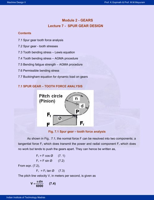
7.1 SPUR GEAR – TOOTH FORCE ANALYSIS<br />
Fig. 7.1 <strong>Spur</strong> gear – tooth force analysis<br />
As shown in Fig.. 7.1, the normal force F can be resolved into two components; a<br />
tangential force Ft which does transmit the power and radial component Fr which does<br />
no work but tends to push the gears apart. They can hence be written as,<br />
From eqn. (7.2),<br />
Ft = F cos Ø (7. 1)<br />
Fr = F sin Ø (7.2)<br />
Fr = Ft tan Ø (7.3)<br />
The pitch line velocity V, in meters per second, is given as<br />
�<br />
� dn<br />
V (7.4)<br />
6000
Machine <strong>Design</strong> II Pr<strong>of</strong>. K.Gopinath & Pr<strong>of</strong>. M.M.Mayuram<br />
t � FV<br />
W ( 7.5)<br />
1000<br />
where d is the pitch diameter <strong>of</strong> the gear in millimeters and n is the rotating speed in<br />
rpm and W power in kW.<br />
7.2 SPUR GEAR - TOOTH STRESSES<br />
<strong>Indian</strong> <strong>Institute</strong> <strong>of</strong> <strong>Technology</strong> Madras<br />
Fig. 7.2 Photo-elastic Model <strong>of</strong> gear tooth<br />
Stresses developed by Normal force in a photo-elastic model <strong>of</strong> gear tooth as per Dolan<br />
and Broghammer are shown in the Fig.. 7.2. The highest stresses exist at regions<br />
where the lines are bunched closest together. The highest stress occurs at two<br />
locations:<br />
A. At contact point where the force F acts<br />
B. At the fillet region near the base <strong>of</strong> the tooth.<br />
7.3 SPUR GEAR - LEWIS EQUATION FOR TOOTH BENDING STRESS<br />
Fig. 7.3 <strong>Gear</strong> tooth as cantilever beam
Machine <strong>Design</strong> II Pr<strong>of</strong>. K.Gopinath & Pr<strong>of</strong>. M.M.Mayuram<br />
Lewis considered gear tooth as a cantilever beam with static normal force F applied at<br />
the tip.<br />
Assumptions made in the derivation are:<br />
1. The full load is applied to the tip <strong>of</strong> a single tooth in static condition.<br />
2. The radial component is negligible.<br />
3. The load is distributed uniformly across the full face width.<br />
4. Forces due to tooth sliding friction are negligible.<br />
5. Stress concentration in the tooth fillet is negligible.<br />
The Fig. 7.3 shows clearly that the gear tooth is stronger through out than the inscribed<br />
constant strength parabola, except for the section at ‘a’ where parabola and tooth pr<strong>of</strong>ile<br />
are tangential to each other.<br />
At point ‘a’, bending stress is<br />
Mc 6Ft h<br />
σ � �<br />
(7.6)<br />
2<br />
I bt<br />
By similar triangles,<br />
t<br />
2<br />
2 h t<br />
� or � 4x (7.7)<br />
x t h<br />
2<br />
Substituting <strong>of</strong> Eqn. (7.7) in Eqn. (7.6), it gives<br />
6Ft<br />
σ �<br />
(7.8)<br />
4bx<br />
� 2x<br />
y ( 7.9)<br />
3p<br />
where ‘y’ is defined as the Lewis form factor .<br />
And substituting Eqn. (7.9) in Eqn. (7.8) we get<br />
Ft<br />
σ �<br />
(7.10)<br />
bpy<br />
Eqn. 7.10 is the basic Lewis equation in terms <strong>of</strong> circular pitch.<br />
In SI units gears are more <strong>of</strong>ten made to standard modules. Hence by substituting<br />
<strong>Indian</strong> <strong>Institute</strong> <strong>of</strong> <strong>Technology</strong> Madras
Machine <strong>Design</strong> II Pr<strong>of</strong>. K.Gopinath & Pr<strong>of</strong>. M.M.Mayuram<br />
p � π m<br />
t F<br />
<strong>Indian</strong> <strong>Institute</strong> <strong>of</strong> <strong>Technology</strong> Madras<br />
in equation (7.10), we get<br />
σ �<br />
(7.11)<br />
b π ym<br />
Let Y = π y, which is known as modified Lewis form factor, then<br />
t F<br />
σ �<br />
(7.12)<br />
bYm<br />
Eqn. 12 is the standard Lewis equation for tooth bending stress based on module.<br />
Both Y and y are functions <strong>of</strong> tooth shape (but not size) and therefore vary with the<br />
number <strong>of</strong> teeth in the gear. These values can be obtained from Table 7.1 or Graph in<br />
Fig. 7.4.<br />
Table 7.1 VALUES OF LEWIS FORM FACTOR
Machine <strong>Design</strong> II Pr<strong>of</strong>. K.Gopinath & Pr<strong>of</strong>. M.M.Mayuram<br />
<strong>Indian</strong> <strong>Institute</strong> <strong>of</strong> <strong>Technology</strong> Madras<br />
Fig. 7.4 spur gear - graph 1 for modified Lewis form factor<br />
The Lewis equation indicates that tooth bending stress varies with the following:<br />
t F<br />
σ �<br />
(7.12)<br />
bYm<br />
(1) Directly with load,<br />
(2) Inversely with tooth width b,<br />
(3) Inversely with tooth size p or m,<br />
(4) Inversely with tooth shape factor y or Y.<br />
Drawbacks <strong>of</strong> Lewis equation are:<br />
1. The tooth load in practice is not static. It is dynamic and is influenced by pitch line<br />
velocity.<br />
2. The whole load is carried by single tooth is not correct. Normally load is shared<br />
by teeth since contact ratio is near to 1.5.<br />
3. The greatest force exerted at the tip <strong>of</strong> the tooth is not true as the load is shared<br />
by teeth. It is exerted much below the tip when single pair contact occurs.<br />
4. The stress concentration effect at the fillet is not considered.
Machine <strong>Design</strong> II Pr<strong>of</strong>. K.Gopinath & Pr<strong>of</strong>. M.M.Mayuram<br />
SPUR GEAR – MODIFIED LEWIS EQUATION FOR BENDING STRESS<br />
The modified Lewis equation for bending stress is,<br />
Ft<br />
σ �<br />
(7.13)<br />
'<br />
K bYm<br />
<strong>Indian</strong> <strong>Institute</strong> <strong>of</strong> <strong>Technology</strong> Madras<br />
v<br />
where K’v is known as velocity factor and is given by Barth’s equation below for known<br />
pitch line velocity V in m/s and is given by,<br />
' 6<br />
K v � (7.14)<br />
6�V Eqn. (7.14) is used for cut or milled teeth or for gears not carefully generated.<br />
' 50<br />
K v �<br />
(7.15)<br />
0.5<br />
50 � (200V)<br />
Eqn. (7.15) is used for hobbed and shaped gears.<br />
' � 78 �<br />
K v � � 0.5<br />
�<br />
� ( 7.16)<br />
� 78 (200V) �<br />
0.5<br />
Eqn. (7.16) is used for high-precision shaved or ground teeth.<br />
The modified Lewis equation given in eqn. 7.13 is used when fatigue failure <strong>of</strong> the gear<br />
teeth is not a problem and a quick estimate is desired for more detailed analysis.<br />
SPUR GEAR - TOOTH BENDING STRESS<br />
Factors that influence gear tooth bending stresses are as follows:<br />
1. Pitch line velocity.<br />
2. Manufacturing accuracy.<br />
3. Contact ratio.<br />
4. Stress concentration.<br />
5. Degree <strong>of</strong> shock loading.<br />
6. Accuracy and rigidity <strong>of</strong> mounting.<br />
7. Moment <strong>of</strong> inertia <strong>of</strong> the gears and attached rotating Members.
Machine <strong>Design</strong> II Pr<strong>of</strong>. K.Gopinath & Pr<strong>of</strong>. M.M.Mayuram<br />
7.4 SPUR GEAR –TOOTH BENDING STRESS (AGMA)<br />
Accommodating the earlier mentioned factors, American <strong>Gear</strong> Manufacturing<br />
Association (AGMA) came up with a refined form <strong>of</strong> Lewis equation as given below:<br />
Ft<br />
σ � K v<br />
bmJ<br />
Ko Km<br />
(7.17)<br />
Where, J = <strong>Spur</strong> gear geometry factor. This factor includes the Lewis form factor Y<br />
and also a stress concentration factor based on a tooth fillet radius <strong>of</strong> 0.35/P. It also<br />
depends on the number teeth in the mating gear.<br />
J= Y<br />
K<br />
<strong>Indian</strong> <strong>Institute</strong> <strong>of</strong> <strong>Technology</strong> Madras<br />
f<br />
(7.18)<br />
Where, Y is the modified Lewis form factor dealt earlier and<br />
Kf is the fatigue stress concentration factor given below:<br />
L M<br />
� t� �t� Kf�H�� � ��<br />
�<br />
�r� � l �<br />
(7.19)<br />
Where, H = 0.34 – 0.458 366 2Ø ------- (7.20)<br />
L = 0.316 – 0.458 366 2Ø ------ (7.21)<br />
M = 0.290 + 0.458 366 2Ø ------ (7.22)<br />
Fig. 7.4.Maximum Tooth loading
Machine <strong>Design</strong> II Pr<strong>of</strong>. K.Gopinath & Pr<strong>of</strong>. M.M.Mayuram<br />
2<br />
rf �(b �rf)<br />
r �<br />
(7.23)<br />
(d/2) �b� rf<br />
Where, rf is the fillet radius, d is the pitch diameter and b is the dedendum.<br />
J value can also be obtained from the Table 7.2 or Fig.7.5<br />
Table 7.2 AGMA Geometry factor J for teeth having Φ = 20 o , a = 1m, b = 1.25m<br />
and rf = 0.3m<br />
<strong>Indian</strong> <strong>Institute</strong> <strong>of</strong> <strong>Technology</strong> Madras<br />
Fig. 7.5 Graph 2 AGMA geometry (J) factor
Machine <strong>Design</strong> II Pr<strong>of</strong>. K.Gopinath & Pr<strong>of</strong>. M.M.Mayuram<br />
<strong>Indian</strong> <strong>Institute</strong> <strong>of</strong> <strong>Technology</strong> Madras<br />
Kv - Velocity factor given by eqns. (7.24) to (7.26)<br />
Ko = overload factor, given in Table 7.3<br />
Km= Load distribution factor, given in Table 7.4<br />
Kv = Velocity or dynamic factor, indicates the severity <strong>of</strong> impact as successive pairs <strong>of</strong><br />
teeth engage. This is a function <strong>of</strong> pitch line velocity and manufacturing accuracy. It is<br />
given by inverse <strong>of</strong> Barth’s equation (7.24), (7.25) & (7.26) or very rough value from the<br />
Fig.7 6.<br />
6�V K v �<br />
(7.24)<br />
6<br />
Eqn. (7.24) is used for cut or milled teeth or for gears not carefully generated.<br />
0.5<br />
50 � (200V)<br />
K v �<br />
(7.25)<br />
50<br />
Eqn. (7.25) is used for hobbed and shaped gears.<br />
0.5<br />
� 78 � (200V) �<br />
K v � � � (7.26)<br />
� 78 �<br />
Eqn. (7.26) is used for high-precision shaved or ground teeth.<br />
0.5<br />
Fig. 7.6 Velocity factor Kv<br />
Ko = Overload factor which reflects the degree <strong>of</strong> non-uniformity <strong>of</strong> driving and load<br />
torques. It is given in Table 7.3
Machine <strong>Design</strong> II Pr<strong>of</strong>. K.Gopinath & Pr<strong>of</strong>. M.M.Mayuram<br />
Km = Load distribution factor which accounts for non-uniform spread <strong>of</strong> the load across<br />
the face width. It depends on the accuracy <strong>of</strong> mounting, bearings, shaft deflection and<br />
accuracy <strong>of</strong> gears.<br />
<strong>Indian</strong> <strong>Institute</strong> <strong>of</strong> <strong>Technology</strong> Madras<br />
Table 7. 3 -Overload factor Ko<br />
Source <strong>of</strong> power<br />
Uniform<br />
Light shock<br />
Medium shock<br />
Uniform<br />
1.00<br />
1.25<br />
1.50<br />
Table 7.4 Load distribution factor Km<br />
Characteristics <strong>of</strong> Support<br />
Accurate mountings, small bearing<br />
clearances, minimum deflection, precision<br />
gears<br />
Less rigid mountings, less accurate gears,<br />
contact across the full face<br />
Accuracy and mounting such that less than<br />
full-face contact exists<br />
Driven Machinery<br />
Moderate Shock<br />
0 - 50<br />
1.3<br />
1.6<br />
1.25<br />
1.50<br />
1.75<br />
Over 2.2<br />
Heavy Shock<br />
1.75<br />
2.00<br />
2.25<br />
Face width ( mm)<br />
150<br />
1.4<br />
1.7<br />
Over 2.2<br />
225<br />
1.5<br />
1.8<br />
Over 2.2<br />
7.5 SPUR GEAR – PERMISSIBLE TOOTH BENDING STRESS (AGMA)<br />
Endurance limit <strong>of</strong> the material is given by:<br />
σe = σe’ kL kv ks kr kT kf km (7.27)<br />
Where, σe’ endurance limit <strong>of</strong> rotating-beam specimen<br />
kL = load factor , = 1.0 for bending loads<br />
400 up<br />
1.8<br />
2.2<br />
Over 2.2
Machine <strong>Design</strong> II Pr<strong>of</strong>. K.Gopinath & Pr<strong>of</strong>. M.M.Mayuram<br />
kv = size factor, = 1.0 for m < 5 mm and<br />
= 0.85 for m > 5 mm<br />
ks = surface factor, is taken from Fig. 7.7 based on the ultimate tensile strength <strong>of</strong> the<br />
material<br />
for cut, shaved, and ground gears.<br />
kr = reliability factor given in Table 7.5.<br />
kT = temperature factor, = 1 for T≤ 350 o C<br />
= 0.5 for 350 < T ≤ 500 o C<br />
Table 7.5 Reliability Factor kr<br />
<strong>Indian</strong> <strong>Institute</strong> <strong>of</strong> <strong>Technology</strong> Madras<br />
Fig. 7.7 Surface factor ks<br />
kf = fatigue stress concentration factor. Since this factor is included in J factor, its value<br />
is taken as 1.<br />
km = Factor for miscellaneous effects. For idler gears subjected to two way bending, =<br />
1. For other gears subjected to one way bending, the value is taken from the<br />
Fig.7.8. Use km = 1.33 for σut less than 1.4 GPa.
Machine <strong>Design</strong> II Pr<strong>of</strong>. K.Gopinath & Pr<strong>of</strong>. M.M.Mayuram<br />
7.6 Permissible bending stress<br />
� e σ<br />
[σ] (7.28)<br />
s<br />
<strong>Indian</strong> <strong>Institute</strong> <strong>of</strong> <strong>Technology</strong> Madras<br />
Fig. 7.8 - Miscellaneous effects factor km<br />
where s is the factor <strong>of</strong> safety.<br />
Hence the design equation from bending consideration is :<br />
σ ≤ [ σ ] (7.29)<br />
7.7 SPUR GEARS – BUCKINGHAM’S DYNAMIC LOAD EQUATION<br />
Buckingham’s dynamic load equation (1932):<br />
According to him, small machining error and deflection <strong>of</strong> teeth under load cause<br />
periods <strong>of</strong> acceleration, inertia forces, and impact loads on the teeth similar to variable<br />
load superimposed on a steady load. The total maximum instantaneous load on the<br />
teeth or dynamic load is Fd
Machine <strong>Design</strong> II Pr<strong>of</strong>. K.Gopinath & Pr<strong>of</strong>. M.M.Mayuram<br />
Fd = Ft + Fi (7.30)<br />
<strong>Indian</strong> <strong>Institute</strong> <strong>of</strong> <strong>Technology</strong> Madras<br />
Fig. 7.9 Dynamic loading on gear<br />
� 9.84V (Cb+F �<br />
t )<br />
F i � � � ( 731 . )<br />
��9.84V + 0.4696<br />
Cb+Ft<br />
��<br />
Where<br />
Fd – dynamic load, N<br />
Ft – transmitted load, N<br />
Fi – increment load due to machining errors and the pitch line velocity<br />
V – pitch line velocity, m/s<br />
b – face width, mm<br />
C – factor depending on machining error<br />
Table 7.6 Value <strong>of</strong> C for spur gears
Machine <strong>Design</strong> II Pr<strong>of</strong>. K.Gopinath & Pr<strong>of</strong>. M.M.Mayuram<br />
<strong>Indian</strong> <strong>Institute</strong> <strong>of</strong> <strong>Technology</strong> Madras<br />
Fig. 7.10 Graph 6 Permissible error<br />
Table 7.7 Expected error in tooth pr<strong>of</strong>ile<br />
SPUR GEARS –BUCKINGHAM’S DYNAMIC LOAD FOR DESIGN<br />
Lewis equation is,<br />
t F<br />
σ �<br />
(7.12)<br />
bYm
Machine <strong>Design</strong> II Pr<strong>of</strong>. K.Gopinath & Pr<strong>of</strong>. M.M.Mayuram<br />
Rearranging eqn 12,<br />
<strong>Indian</strong> <strong>Institute</strong> <strong>of</strong> <strong>Technology</strong> Madras<br />
Ft = σ b Y m (7.32)<br />
If we substitute permissible stress in Eqn. (7.32) we get on the right side, beam or tooth<br />
strength <strong>of</strong> the gear Ftd as,<br />
Ftd = [σ] b Y m (7.33)<br />
From design point <strong>of</strong> view Ftd � Fd<br />
-----------