
You also want an ePaper? Increase the reach of your titles
YUMPU automatically turns print PDFs into web optimized ePapers that Google loves.
P A I N T S P R A Y I N G E Q U I P M E N TPISTON PNEUMATIC TRANSFER <strong>PUMP</strong>SWORKING PRINCIPLEThe pneumatic transfer pumps work with a compressed air motor that moves the piston vertically from topto bottom and viceversa. The product is suctioned by the lower pump and carried to the exit.The structure of the "pumping unit" (suction valve, pump piston, material seal gaskets) permits the supply ofmaterial when the piston is in the ascending or descending phase.The flow rate of a pneumatic piston pump depends on the quantity of material that it releases during eachcycle and on the number of cycles that it completes (the cycle is the full stroke of the piston in both directions).Pneumatic piston pumps are divided into two types:IN-LINE: the pneumatic motor and the pump constitute one single bodyDIVORCED: the pneumatic motor is separated from the pump and the fluid is not in contact with the motor.ADVANTAGES OF USE- Air supply- Excellent resistance to abrasion and corrosion- Ability to manage different applications that range from the flow of corrosive fluids to the cleaning fluids- Constant balancing over a wide viscosity range reduces the pressure drop during the run- Larius piston pumps are ATEX certified- Stainless steel or carbon steel models are suitable for most of the applicationswww.<strong>larius</strong>.com
Due to a constant product improvement programme, the factory reserves the rightto modify technical details mentioned in this manual without prior notice.This manual is to be considered as an English language translation of theoriginal manual in Italian. The manufacturer shall bear no responsibility for anydamages or inconveniences that may arise due to the incorrect translation of theinstructions contained within the original manual in Italian.
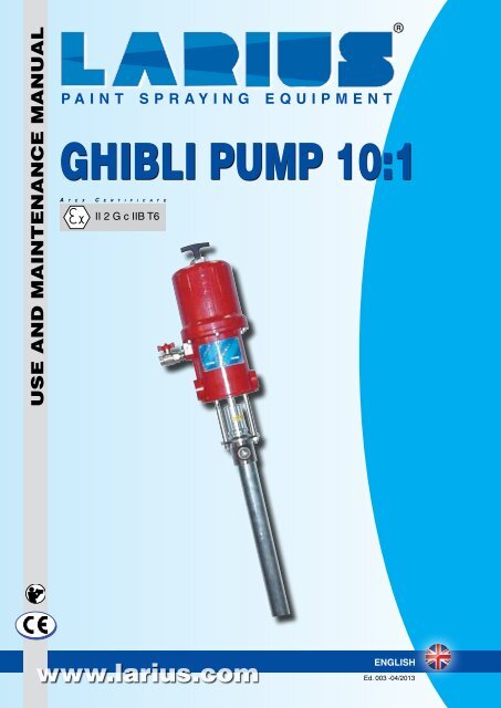
0 BAR 0 PSI0<strong>GHIBLI</strong> <strong>10</strong>:1WARNINGSThe table below provides the meaning of the symbols used in this manual in relation to using, earthing,operating, maintaining, and repairing of this equipment.Read this operator’s manual carefully before using the equipment.An improper use of this machine can cause injuries to people or things.Do not use this machine when under the influence of drugs or alcohol.Do not modify the equipment under any circumstances.Use products and solvents that are compatible with the various parts of the equipment, and read the manufacturer’s warnings carefully.See the Technical Details for the equipment given in the Manual.Check the equipment for worn parts once a day. If any worn parts are found, replace them using ONLY original spare parts.Keep children and animals away from work area.Comply with all safety standards.It indicates an accident risk or serious damage to equipment if this warning is not followed.FIRE AND EXPLOSION HAZARDSolvent and paint fumes in working area can ignite or explode.To help prevent fire and explosion:• Use equipment ONLY in well ventilated area. Keep working area free from debris.• Eliminate all ignition sources, such as pilot lights, cigarettes and plastic drop cloths (potential static arc).• Ground equipment and conductive objects.• Use only grounded airless conductive hoses.• Do not use trichloroethane, methylene chloride, other halogenated hydrocarbon solvents or fluids containing suchsolvents in pressurized aluminium equipment. Such use can cause serious chemical reaction and explosion.• Do not form connections or switch light switches on or off if the air contains inflammable fumes.If electrical shocks or discharges are encountered, immediately stop the operation of the equipment.Keep a fire extinguisher at hand close to the working area.It indicates wound and finger squashing risk due to movable parts in the equipment.Keep far from moving parts.Do not use the equipment without the proper protection.Before any inspection or maintenance of the equipment, carry out the decompression procedure explained in this manual, and preventany risk of the equipment starting unexpectedly.Report any risk of chemical reaction or explosion if this warning has not been given.There is a risk of injury or serious lesion related to contact with the jet from the spray gun. If this should occur, IMMEDIATELY contacta doctor, indicating the type of product injected.Do not spray before the guard has been placed over the nozzle and the trigger on the spray gun.Do not put your fingers in the spray gun nozzle.Once work has been completed, before carrying out any maintenance, complete the decompression procedure explained in this manual.It indicates important recommendations about disposal and recycling process of products in accordance with the environmental regulations.Mark any clamps attached to earth cables.Use ONLY 3-wire extension cords and grounded electrical outlets.Before starting work make sure that the electrical system is earthed and that it complies with safety standards.High-pressure fluid from gun, hose leaks, or ruptured components will pierce skin.To help prevent injection or fire, always:- Engage trigger lock when not spraying.- Do not put your hand over the spray tip. Do not stop or deflect leaks with your hand, body or other.- Do not point gun at anyone or at any part of the body.- Never spray without tip guard.- Do pressure relief if you stop spraying or being servicing sprayer and before any maintenance operations.- Do not use components rated less than sprayer Maximum Working Pressure.- Never allow children to use this unit- Brace yourself; gun may recoil when triggered.If high pressure fluid pierces your skin, the injury might look like “just a cut”, but it is a serious wound! Getimmediate medical attention.It is obligatory to wear suitable clothing as gloves, goggles and face shield.Wear clothing that complies with the safety standards in force in the country in which the equipment is used.Do not wear bracelets, earrings, rings, chains, or anything else that may hinder the operator’s work.Do not wear clothing with wide sleeves, scarves, ties, or any other piece of clothing that could get tangled up in moving parts of theequipment during the work, inspection, or maintenance cycles.2www.<strong>larius</strong>.comEd. 003 - 04/2013
<strong>GHIBLI</strong> <strong>10</strong>:1ADESCRIPTION OF THE EQUIPMENTGhibli pump <strong>10</strong>:1 is a pneumalic pump to be usedfor low and medium pressure transferring of fluids.Ghibli pump is essentially constituted of an air motorand a structure called "material pumping group" orsimply "pumping group".In the pneumatic motor, the compressed air causes thevertical reciprocating movement of the motor piston.This movement is transmitted through a connectingrod to the material pumping piston.So doing the pump sucks in the fluid to be sent tothe outlet.The ratio <strong>10</strong>:1 means that the outlet pressure ofmaterial is <strong>10</strong> times higher than the pump feed airpressure.3124567POS.DescriptionPOS.Description1234Pump feed air inletOpening-closing valve for air passageHandlePneumatic motor567Material outletFluid pumping tubeMaterial inletEd. 003 - 04/2013www.<strong>larius</strong>.com 3
<strong>GHIBLI</strong> <strong>10</strong>:1ABTECHNICAL DATAMAXIMUM WORKING PRESSURE70 bar (<strong>10</strong>15 psi)<strong>PUMP</strong> AIR PRESSURE3-7 bar (40-<strong>10</strong>0 psi)FEED AIR INLET *1/2" GAS (F)MAXIMUM DELIVERY12 l/min (3-2 gpm)CYCLES PER LITRE 5MAX NUMBER OF CYCLES PER MINUTE 60FLUID OUTLET (CYLINDRICAL GAS) 3/4"NOISE PRESSURE LEVEL< 80 dB(A)* The pump is supplied with a bayonet connection.PARTS OF THE <strong>PUMP</strong> IN CONTACT WITH THE MATERIALPumping group: GALVANIZED CARBON STEEL or STAIN-LESS STEEL (AISI 303 - AISI 304 - AISI 420B)Sealing balls: STAINLESS STEEL AISI 420BGaskets: PTFE, VitonAlways observe these instructions carefullywhen evaluating the product compatibilityand in case of disposal of some parts of thepump no more usable in order to meet the environmentalregulations on recycling process.OTHER PARTS OF THE <strong>PUMP</strong>Motor casing and motor piston: ALUMINIUML/MIN<strong>10</strong>00800600400AIR CONSUMPTION7 BAR5 BAR3 BAR<strong>PUMP</strong>LONGMEDIUMSHORTWEIGHT17 Kg16 Kg15 Kg1254402001860 3 6 9 12 L/MIN<strong>PUMP</strong> DELIVERY4401155 (LONG VERSION)635 (MEDIUM VERSION)1640 (LONG VERSION)1120 (MEDIUM VERSION)515955Ø7357035Ø120121M 36x24www.<strong>larius</strong>.comEd. 003 - 04/2013
<strong>GHIBLI</strong> <strong>10</strong>:1CDTRANSPORTAND UNPACKING• The packed parts should be handled as indicated in thesymbols and markings on the outside of the packing.• Before installing the equipment, ensure that the area tobe used is large enough for such purposes, is properlylit and has a clean, smooth floor surface.The user is responsible for the operations of unloadingand handling and should use the maximum care so asnot to damage the individual parts or injure anyone.To perform the unloading operation, use only qualifiedand trained personnel (truck and crane operators, etc.)and also suitable hoisting equipment for the weight ofthe installation or its parts.Follow carefully all the safety rules.The personnel must be equipped with the necessarysafety clothing.• The manufacturer will not be responsible for the unloadingoperations and transport to the workplace ofthe machine.• Check the packing is undamaged on receipt of theequipment. Unpack the machine and verify if therehas been any damage due to transportation.In case of damage, call immediately LARIUS and theShipping Agent. All the notices about possible damageor anomalies must arrive timely within 8 days at leastfrom the date of receipt of the plant through RegisteredLetter to the Shipping Agent and to LARIUS.The disposal of packaging materials is a customer’scompetence and must be performed in accordancewith the regulations in force in the country where theplant is installed and used.It is nevertheless sound practice to recycle packagingmaterials in an environment-friendly manner as muchas possible.SAFETY RULES• The employer shall train its employees aboutall those risks stemming from accidents, aboutthe use of safety devices for their own safetyand about the general rules for accidentprevention in compliance with internationalregulations and with the laws of the countrywhere the plant is used.• The behaviour of the employees shall strictlycomply with the Accident prevention AND ALSOENVIRONMENTAL regulations in force in thecountry where the plant is installed and used.Read carefully and entirely the following instructionsbefore using the product. Please save theseinstructions in a safe place.The unauthorised tampering/replacement of oneor more parts composing the machine, the use ofaccessories, tools, expendable materials other thanthose recommended by the manufacturer can bea danger of accident.The manufacturer will be relieved from tort andcriminal liability.• KEEP YOUR WORK PLACE CLEAN AND TIDY. DISORDERWHERE YOU ARE WORKING CREATES A POTENTIAL RISKOF ACCIDENTS.• ALWAYS KEEP PROPER BALANCE AVOIDING UNUSUALSTANCE.• BEFORE USING THE TOOL, ENSURE THERE ARE NOTDAMAGED PARTS AND THE MACHINE CAN WORK PRO-PERLY.• ALWAYS FOLLOW THE INSTRUCTIONS ABOUT SAFETYAND THE REGULATIONS IN FORCE.• Keep those who are not responsible for theequipment out of the work area.• NEVER exceed the maximum working pressureindicated.• NEVER point the spray gun at yourselves orat other people. THE CONTACT WITH THE CASTINGCAN CAUSE SERIOUS INJURIES. In case of injuriescaused by the gun casting, seek immediate medicaladvice specifying the type of the productinjected. Never undervalue a wound caused bythe injection of a fluid.• Always DISCONNECT THE SUPPLY AND release thepressure in the circuit before performingany check or part replacement of the equipment.• NEVER MODIFY ANY PART IN THE EQUIPMENT. CHECKREGULARLY THE COMPONENTS OF THE SYSTEM. RE-PLACE THE PARTS DAMAGED OR WORN.• Tighten and check all the fittings for connectionbetween pump, flexible hose and spray gunbefore using the equipment.• Always use the flexible hose supplied with standardkit. THE USE OF ANY ACCESSORIES OR TOOLINGOTHER THAN THOSE RECOMMENDED IN THIS MANUAL,MAY CAUSE DAMAGE OR INJURE THE OPERATOR.• The fluid contained in the flexible hose canbe very dangerous. Handle the flexible hosecarefully. Do not pull the flexible hose tomove the equipment. Never use a damaged or arepaired flexible HOSE.Ed. 003 - 04/2013www.<strong>larius</strong>.com 5
<strong>GHIBLI</strong> <strong>10</strong>:1The high speed of the product in the hose can createstatic electricity through discharges and sparks.It is suggested to earth the equipment. The pumpis earthed through the earth cable of the supply.The gun is earthed through the high pressureflexible hose. All the conductors near the workarea must be earthed.AEEXAMPLES OF USE<strong>GHIBLI</strong> <strong>10</strong> :1 pump can be used in different ways according to themodel and conditions of use. Here below some examples of the applicationof the <strong>GHIBLI</strong> <strong>10</strong> :1 pump and of the relevant accessoriesare shown.• NEVER SPRAY OVER FLAMMABLE PRODUCTS OR SOL-VENTS IN CLOSED PLACES.• NEVER USE THE EQUIPMENT IN POTENTIALLY EXPLO-SIVE ENVIRONMENTS.Always check the product is compatible with thematerials composing the equipment (pump, spraygun, flexible hose and accessories) with which itcan come into contact. Never use paints or solventscontaining halogen hydrocarbons (as themethylene chloride).If these products come into contact with aluminiumparts can provoke dangerous chemical reactionswith risk of corrosion and explosion.IF THE PRODUCT TO BE USED IS TOXIC, AVOIDINHALATION AND CONTACT BY USING PRO-TECTION GLOVES, GOGGLES AND PROPERFACE SHIELDS.TAKE PROPER SAFETY MEASURES FOR THEPROTECTION OF HEARING IN CASE OF WORKNEAR THE PLANT.1<strong>GHIBLI</strong> <strong>10</strong> :1 pump long version, for transferring from 200 lt. drumsfixed on pneumatic ram or directly on drum.POS. REF. DESCRIPTION15<strong>10</strong>500 Pneumatic ram 200 lt. - single column5<strong>10</strong>000 Pneumatic ram 200 lt. - double column2 5<strong>10</strong>777 Shovel plate3 3460 Adapter for fastening to a 200 lt drum23AVOID APPROACHING TOO MUCH TO THE <strong>PUMP</strong>PISTON ROD WHEN THE <strong>PUMP</strong> IS WORKING ORUNDER PRESSURE. A SUDDEN MOVEMENT OF THEPISTON ROD CAN CAUSE WOUNDS OR FINGERSQUASHING.1condiTIONS OF GUARANTEEThe conditions of guarantee do not apply in thefollowing situations:- improper washing and cleaning of componentscausing malfunction, wear or damage to the equipmentor any of its parts;- improper use of the equipment;- use that does not conform with applicable nationallegislation;- incorrect or faulty installation;- modifications, interventions and maintenance thathave not been authorised by the manufacturer;- use of non-original spare parts or parts that donot correspond to the specific model;- total or partial non-compliance with the instructionsprovided.<strong>GHIBLI</strong> <strong>10</strong> :1 pump medium version, for transferring from 60 and 30lt. drums fixed on trolley mounted pneumatic ram.POS. REF. DESCRIPTION15<strong>10</strong>600 Trolley mounted pneumatic ram - single column5<strong>10</strong>090 Pneumatic ram 30 lt. - double column2 5<strong>10</strong>781 Shovel plate for 30 lt. drums26www.<strong>larius</strong>.comEd. 003 - 04/2013
<strong>GHIBLI</strong> <strong>10</strong>:1AGoperationCheck all the fittings for connection of the differentcomponents (pump, flexible hose, spray gun, etc.)before using the equipment.1• Dip the fluid pumping hose into the product tank (for thesuction threaded valve version, dip the flexible suction hose).F2<strong>GHIBLI</strong> <strong>10</strong> :1 pump short version, with suction threaded valve fixedon wall support and with flexible suction hose.POS. REF. DESCRIPTION1 96038 Wall support216608 Flexible suction hose with stainless dip tube16612 Flexible suction hose with stainless steel dip tubeSETTING-UPCONNECTION TO THE FEED AIRFor pump feed use a tube with an internal diameter no lowerthan <strong>10</strong> mm.Install at the inlet of the pump an air pressureregulator (it is suggested complete with condensatefilter and lubricator). The outlet pressureof the material is <strong>10</strong> times the inlet pressureof the pump feed air. Therefore, it is extremely important toadjust the value of the feed air pressure.CONNECTION OF THE FLUID OUTLET HOSEConnect the high pressure hose to the outlet of the pump.It is recommended to tighten the fittings.WASHING OF THE BRAND NEW EQUIPMENTThe pump has been tested at our factory with light mineral oil, leftinside the pumping element as protection. Before sucking the fluid,wash with diluent. To wash the equipment follow the procedure"Cleaning at the end of the work" described on page 7.• Make the compressed air flow into the pump. It is advisableto adjust air pressure to minimum value necessary for itscontinuous working.• When the product chamber is full, pump will start working andthen stop. Pump will start working again every time the triggerof the spray gun is pressed or the delivery valve is opened.• Check that the packing nut is not loosened causing the comingout of the product. To tighten the packing nut follow theinstructions indicated in the section "Routine maintenance"on page 8.AHCLEANING AT END OF WORK• Stop the air supply to the pump.• Lift the pump and dip the pumping hose into the tank containingwashing solvent or a washing liquid specific for the productsto be used with the pump (for suction threaded valve version,lift the flexible hose).• Make compressed air flow into the pump. It is advisable toadjust the air pressure to minimum value necessary to itscontinuous working.• Point the spray gun or the delivery valve at a collecting tankand drain all the product left inside the pump till a cleanwashing product comes out.• Now stop the air supply to the pump and release the residualpressure.• In case of long activity, the operations of sucking and leavinglight mineral oil inside the pumping element are suggested.Store possible dangerous fluids in propercontainers. Their disposal must be performedin accordance with the regulations in forceabout the industrial waste goods.Ed. 003 - 04/2013www.<strong>larius</strong>.com 7
<strong>GHIBLI</strong> <strong>10</strong>:1AIROUTINE MAINTENANCEAlways close the compressed air supply and releasethe pressure in the plant before performingany check or maintenance of the pump.• Daily check (and every time the pump is operated after a longstorage) the packing nut is not loosened, causing otherwisethe coming out of the product.To tighten the packing nut use a metal rod (I1) with a diameterof 6 mm (see the illustration). The packing nut must betightened so as to avoid the seizure of the pumping pistonand the eccesive wear of sealing gaskets.In case of persistent coming out of product, provide for thereplacement of the upper sealing gaskets (see on page 12).• To prevent the product from drying up on the piston rod, keepthe packing nut filled with lubricant.• Periodically check the air supply to the pump. Ensure the airis always clean and lubricated.I18www.<strong>larius</strong>.comEd. 003 - 04/2013
<strong>GHIBLI</strong> <strong>10</strong>:1LTROUBLESHOOTINGProblem• The pump does not start• Accelerated working and no pressureof the pump• The pump works but the flow ofproduct is not sufficientPossible cause• Feed air not sufficient• Outlet product line clogged• Inlet product line clogged• Pneumatic motor blocked at the upperor lower stroke end (Dead Center)• Crosspiece screws failure of the pneumaticmotor• Lack of product• The pumps sucks air• The product is too fluid• Gaskets of the pumping rod worn• The ball of the suction valve does notperfectly "close"• Air feed pressure is too low• Gaskets of the pumping rod worn• Inlet product line clogged• Product is too thick• The ball of the suction valve does notperfectly "close"Solution• Check on the air supply line.Increase the diameter of the feedhose.• Clean. Disconnect the outlet hose ofthe product.Feed the pump at he minimum pressureand verify if the pump startswithout the outlet hose.• Clean the suction pipe.• Reduce feed pressure;• Manually reset the pneumatic motor(see on page <strong>10</strong>);• Replace the screws (see on page <strong>10</strong>).• Add product.• Check the flexible suction hose(only for suction threaded valve version).• Adjust the suction valve(see on page 11).• Replace the lower gaskets(see on page 12).• Disassemble the suction valve andclean (see on page 11).• Increase air pressure.• Replace the lower gaskets (see onpage 12).• Clean the suction pipe.• Adjust the suction valve(see on page 11).• Disassemble the suction valve andclean (see on page 11).Always close the compressed air supply and release the pressure in the plant before performing any check orreplacement of parts of the pump.Ed. 003 - 04/2013www.<strong>larius</strong>.com 9
<strong>GHIBLI</strong> <strong>10</strong>:1AMMANUAL RESET OF THEPNEUMATIC MOTOR• The feed air pressure of the pump must never be higher thanthe maximum value indicated in the technical data (see p. 4).Exceed this value can block the valves of the pneumatic motorin the upper or lower position (Dead Center).• To start again a blocked motor, close the air supply and releasepressure in the circuit. This operation should allow therecovery of the valves.• In case the motor is blocked, proceed as follows:Close the air supply to the pump and release theresidual pressure in the plant.N1Immediately replace the plug with a usual M8nut before the guide rod slides into the cylinder(see illustration below).• Remove the screws (N3).• Carefully extract the motor cylinder (N4) from the pump.N2• Unscrew the eyebolt or handle plug (M1) and pull it upwardstogether with the guide rod (M2) so allowing the manual releaseof the stroke reversal group.• Screw again the plug.M1M2N4ANDISASSEMBLY OF THE PNEU-MATIC MOTORClose the compressed air supply to the pumpand release the residual pressure in the plant.• Unscrew the eyebolt or handle plug (N1) and pull it upwardstogether with the guide rod (N2).• Hold the guide rod and remove the plug (using two wrenches).N3<strong>10</strong>www.<strong>larius</strong>.comEd. 003 - 04/2013
<strong>GHIBLI</strong> <strong>10</strong>:1• Check the condition of every part of the motor.• For any replacement of the screws (N5) of the crosspiece(N6), for their reassembly and correct adjustment see thedrawing below and the exploded view on page 14.AODISASSEMBLY OF THESUCTION VALVEClose the compressed air supply to the pumpand release the residual pressure in the plant.• Lift the pump from the fluid tank.If the product to be used is toxic or aggressive,provide for all the individual protection devicesnecessary to avoid the contact with the productduring the disassembly of the pump.• Unscrew the suction valve.• Remove the stop ball pin (O1) and the ball (O2). Check thatball housing and ball are not ruined: then clean and/or replacethe parts.N5• Insert again the ball and the stop ball pin. Adjust the ballstroke according to the type of product being used. For thickproducts, the maximum of the stroke (place the stop ball pinin connection with the upper holes of the suction valve). Forvery fluid products, the contrary.O2N63,5 mmO1Ed. 003 - 04/2013www.<strong>larius</strong>.com 11
<strong>GHIBLI</strong> <strong>10</strong>:1APREPLACEMENT OF THELOWER GASKETS• Carefully screw again the fluid cylinder (it is suggested to laya slight film of vaseline grease on the internal walls of the fluidcylinder).Close the compressed air supply to the pumpand release the residual pressure in the plant.• Unscrew and remove the fluid cylinder (P1).• Hold the bush (P2) with a wrench and with the other wrenchunscrew the fitting (P3).• Exctract the necessary lower gaskets (P4), supplied as spareparts.• For the reassembling of the gaskets, respect the order asshown in the drawing.P2CHECK THEGASKETS:REPLACEIF WORNP4P3P1AQREPLACEMENT OF THEUPPER GASKETSClose the compressed air supply to the pumpand release the residual pressure in the plant.• Unscrew and extract the fluid cyclinder (Q1).• Unscrew the three nuts (Q2).• Remove the split pin (Q3) and unscrew the piston rod fromthe pneumatic motor. Disconnect the pumping group from thepneumatic motor.12www.<strong>larius</strong>.comEd. 003 - 04/2013
<strong>GHIBLI</strong> <strong>10</strong>:1Q3Q2Q1• Extract the piston rod from the housing.• Unscrew the packing nut (Q4) (use a metal rod with an internaldiameter of 6 mm).• Remove the gaskets and packing glands.• For the correct reassembling of the gaskets see the illustrationbelow and the exploded view on page 16.Q4NOTEATTENTION!FOR THE REASSEMBLINGOF THE GASKETS, RE-SPECT THE ORDER ASSHOWN IN THE DRAWING.Tighten the packing nut only after inserting againthe piston rod into the housing (it is suggestedto insert the piston rod from the top to avoid toruin the gaskets).Ed. 003 - 04/2013www.<strong>larius</strong>.com 13
<strong>GHIBLI</strong> <strong>10</strong>:1AR COMPLETE PNEUMATIC MOTOR REF. 96669WARNING: always indicate code and quantity for every part required.1A1234567141589<strong>10</strong>11121311<strong>10</strong>9171618192021222337 38 39243625262827323340304031343514www.<strong>larius</strong>.comEd. 003 - 04/2013
<strong>GHIBLI</strong> <strong>10</strong>:1POS. REF. DESCRIPTION Q.TY1 91603 Handle plug 11A 91602 Handle 12 95075 O-Ring 13 96003 Motor cylinder 14 96005 Roll 25 96006 Spring 26 96007 Fork 27 96024 Fork pin 28 96008 Rocker 19 (2) 4<strong>10</strong>8 Nut M8 4<strong>10</strong> (2) 32024 Washer 211 (1) (2) 96111 Gasket 412 (2) 96112 Bush 213 961<strong>10</strong> Traverse 114 (1) 96012 O-Ring 115 960<strong>10</strong> Guiding rod 116 (1) (2) 96009 Rubber valve 217 96025 Screw M4 218 96011 Traverse guide spring 219 96013 Motor piston 1POS. REF. DESCRIPTION Q.TY20 (1) (2) 96027 Comple valve screw 221 33031 Washer 122 96016 Piston rod 123 96017 Complete bush 124 (1) 96020 O-Ring 125 96018 O-Ring 126 96021 Motor support 127 962<strong>10</strong> Ground plate 128 96211 Screw M6 130 96031 Screw M8 631 96022 Front name plate 132 96609 Back name plate 133 96028 Screw M4 1234 96072 Tie rod 335 96080 Nut M<strong>10</strong> 336 96252 Nipple 1/2" GAS 137 96253 Cock 1/2" GAS 138 96261 Reduction 139 <strong>10</strong><strong>10</strong>3 Bayonet connection 140 96022/1 Felt seal 2(1)Code 40050 Motor gaskets kit(2)Code 40401 Traverse screws kitEd. 003 - 04/2013www.<strong>larius</strong>.com 15
<strong>GHIBLI</strong> <strong>10</strong>:1AS COMPLETE <strong>PUMP</strong>ING GROUP <strong>GHIBLI</strong> <strong>10</strong>:1 <strong>PUMP</strong> - SPLITWARNING: always indicate code and quantity for every part required.123REF.DESCRIPTION96674 Long pumping group431696676 Medium pumping group96675 Short pumping group18517618978<strong>10</strong>1112131932202122232425232021142615272829303116www.<strong>larius</strong>.comEd. 003 - 04/2013
<strong>GHIBLI</strong> <strong>10</strong>:1POS. REF. DESCRIPTION Q.TY1 96073 O-Ring 12 96670 Pin 13 3323 Split pin 24 9<strong>10</strong>08 O-Ring 15 980<strong>10</strong> Piston rod 16 9<strong>10</strong>01/1 Oil tank 17 3429 O-Ring 18 91371/2 Packing nut 19 91371 Complete tank 1<strong>10</strong> (1) (2) 91372 PTFE ring 211 98018 Female V ring 112 (1) (2) 91375 Gasket 413 98011 Male V ring 114 91379 Gaskets housing 115 91380 O-Ring 191341 Long fluid cylinder 116 91342 Medium fluid cylinder 191346 Short fluid cylinder 196671 Long tie rod 117 96673 Medium tie rod 196672 Short tie rod 1POS. REF. DESCRIPTION Q.TY18 8<strong>10</strong><strong>10</strong> Nut M12 219 91334 Bush 120 95021 Ball Ø 7/8" 121 98006 Washer 222 (2) 91336 Comb spring (x leather gasket) 223(1)(2)91384 PTFE gasket (standard) 291337 Leather gasket (upon request) 224 (1) (2) 91338 O-Ring 125 98008 Ring 126 98009 Fitting 127 95027 Ball Ø 1.1/4" 128 (1) (2) 3397 O-Ring 129 98023 Stop ball pin 130 91385 Complete suction ball 191392 Compl. M36x2 suction valve 131 96696 Compl. 1" GAS suction valve 196695 Compl. 3/4" GAS suction valve 132 34005 Split pin (x short version only) 1(1)Code 40236 PTFE gaskets kit(2)Code 40237 Leather gaskets kitEd. 003 - 04/2013www.<strong>larius</strong>.com 17
<strong>GHIBLI</strong> <strong>10</strong>:1ATCOMPLETE <strong>PUMP</strong>ING GROUP <strong>GHIBLI</strong> <strong>10</strong>:1 <strong>PUMP</strong> - SPLIT ST. STEELWARNING: always indicate code and quantity for every part required.1243315REF.DESCRIPTION98050 Long pumping group98052 Medium pumping group98051 Short- pumping group516186978<strong>10</strong>11121314171819222021232425232126272829303118www.<strong>larius</strong>.comEd. 003 - 04/2013
<strong>GHIBLI</strong> <strong>10</strong>:1POS. REF. DESCRIPTION Q.TY1 96073 O-Ring 12 96670 Pin 13 3323 Split pin 24 9<strong>10</strong>08 O-Ring 15 980<strong>10</strong> Piston rod 16 9<strong>10</strong>01/1 Oil tank 17 3429 O-Ring 18 91371/2 Packing nut 19 91371 Complete tank 1<strong>10</strong> (1) 91372 PTFE ring 211 98018 Female V ring 112 (1) 91375 Gasket 413 98011 Male V ring 114 98012 Gaskets housing 115 91380 O-Ring 198019 Long fluid cylinder 116 98020 Medium fluid cylinder 198021 Short fluid cylinder 198060 Long tie rod 117 98062 Medium tie rod 198061 Short tie rod 118 3806 Nut M12 219 98005 Bush 120 95021 Ball Ø 7/8" 1POS. REF. DESCRIPTION Q.TY21 98006 Washer 222 3805 Split pin (for short vers. only) 123 (1) 91384 PTFE gaskets 224 (1) 91338 O-Ring 125 98008 Ring 126 98009 Fitting 127 95027 Ball Ø 1.1/4" 128 (1) 3397 O-Ring 129 98023 Stop ball pin 130 98016 Complete suction valve 198031 Compl. M36x2 suction valve 131 98033 Compl. 1"GAS suction valve 198032 Compl. 3/4"GAS suct. valve 1(1)Code 40236 PTFE gaskets kitEd. 003 - 04/2013www.<strong>larius</strong>.com 19
<strong>GHIBLI</strong> <strong>10</strong>:1AU ACCESSORIesCode 40236 - PTFE GASKETS KITCode 40237 - LEATHER GASKETS KITCode 40238 - PTFE + LEATHER GASKETS KITCode 40401 - TRAVERSE SCREWS KITCode 40050 - MOTOR KITCode 96038: WALL MOUNTING BRACKETCode 16608: SUCTION HOSE + THICK PRODUCTS FILTERCode 16612: ST. STEEL SUCT. HOSE + THICK PRODUCTS FILTERCode 91<strong>10</strong>7: AIR PRESSURE REGULATOR + CONDENSATION FILTERPOST RAMcomplete w/ regulators and compressed air pressure gaugesCode 5<strong>10</strong>500: single-cylinder double-effect post ram forlt.30 up to max lt.200 drumsCode 5<strong>10</strong>600: single-cylinder double-effect post ram forlt.30 up to max lt.60 drumsCode 5<strong>10</strong>090: double post ram for max lt.60 drums.AV AVAILABLE VERSIONSCODE DESCRIPTION96660 LONG STANDARD VERSION96665 MEDIUM STANDARD VERSION96668 SHORT STANDARD VERSIONCODE DESCRIPTION96661 LONG STAINLESS STEEL VERSION96666 MEDIUM STAINLESS STEEL VERSION96667 SHORT STAINLESS STEEL VERSION20www.<strong>larius</strong>.comEd. 003 - 04/2013
<strong>GHIBLI</strong> <strong>10</strong>:1ATEX CERTIFICATIONSafety instructions for using <strong>GHIBLI</strong> series pneumatic piston transfer pumps in high risk environmentswhere potentially explosive gasses or vapours are present.WDESCRIPTIONThese safety instructions refer to the installation, use and maintenanceof LARIUS <strong>GHIBLI</strong> series pneumatic piston transfer pumpsin high risk environments where potentially explosive gasses orvapours are present.These instructions, along with the indicationsprovided in the user and maintenancemanual, must be fully respected.LARIUS <strong>GHIBLI</strong> SERIES PNEUMATIC PISTON<strong>PUMP</strong>S ARE GROUP II MECHANICAL DEVI-CES FOR USE IN AREAS WHERE GASSESCLASSIFIED AS IIB (CATEGORY 2 G) AREPRESENT. THEY ARE DESIGNED AND BUILTIN ACCORDANCE WITH THE 94/9/EC ATEXDIRECTIVE, BASED ON THE FOLLOWINGEUROPEAN STANDARDS: EN 1127-1, EN13463-1ED EN 13463-5.XTECHNICAL CHARACTERISTICSThe main characteristics of the <strong>GHIBLI</strong> series pneumatic pistonpumps are provided in the table belowType Rapport Pressure Ø Air inlet Ø Input Ø Output Max working MaxStandard INOX alimetation matetial material pressure flow96700 967<strong>10</strong> 3:1 3 ÷ 7 bar GC 1/2" Valve Ball GC 1" 21 bar 45 l/min96701 96755 3:1 3 ÷ 7 bar GC 1/2" Valve Ball GC 1" 21 bar 45 l/min96705 96715 3:1 3 ÷ 7 bar GC 1/2" Valve Ball GC 1" 21 bar 45 l/min96660 96661 <strong>10</strong>:1 3 ÷ 7 bar GC 1/2" Valve Ball GC 3/4" 70 bar 12 l/min96665 96666 <strong>10</strong>:1 3 ÷ 7 bar GC 1/2" Valve Ball GC 3/4" 70 bar 12 l/min96668 96667 <strong>10</strong>:1 3 ÷ 7 bar GC 1/2" Valve Ball GC 3/4" 70 bar 12 l/min96870 - 24:1 3 ÷ 7 bar GC 1/2" Piattello GC 3/4" 168 bar 4 l/min96805 - 24:1 3 ÷ 7 bar GC 1/2" Piattello GC 3/4" 168 bar 4 l/min96050 96056 30:1 3 ÷ 7 bar GC 3/4" Valve Ball GC 3/8" 2<strong>10</strong> bar 3,8 l/min96055 96057 40:1 3 ÷ 7 bar GC 3/4" Valve Ball GC 3/8" 280 bar 3 l/minMaximum number of cycles per minute: 60Room temperature: -20°C to +60°CMaximum fluid temperature [°C]: 60°CEd. 003 - 04/2013www.<strong>larius</strong>.com 21
<strong>GHIBLI</strong> <strong>10</strong>:1YMARKINGS3X II 2 G c IIB T6 Tamb: -20°C ÷ + 60°C Tmax. fluido: 60°C Tech. File: <strong>GHIBLI</strong>/ATX/08II2GcT6- 20°C ÷ + 60°C60°Cxxxxx/AAGroup II (surfaces)Category 2 (zone 1)Explosive atmosphere containing gasses, vapours or mistsDesign safety “c”Temperature class T6Room temperatureMaximum process fluid temperatureSerial number or lot number(xxxxx = PROGRESSIVE / year = AA)Correspondence between hazardous areas, substances and categoriesHAZARDOUS AREASCATEGORIES ACCORDING TO THE94/9/EC DIRECTIVEGasses, vapours or mistsGasses, vapours or mistsGasses, vapours or mistsZone 0Zone 1Zone 21G2G or 1G3G, 2G or 1GZSAFETY INSTRUCTIONS FORINSTALLATION IN HAZARD-OUS AREASRead the indications provided in the user andmaintenance manual carefully prior to installation.All of the maintenance operations mustbe performed according to the indicationsprovided in the manual.• The grounding wire for the pumps indicated above must begrounded using an appropriate anti-loosening connection.• The tubes used to connect the delivery and suction linesmust be either metallic, plastic with metallic braid, or plasticwith fabric braid and a suitable grounding conductor.• The pumps must be installed on properly grounded metallicor antistatic drums.• The gases or vapours of any flammable liquids presentmust belong to group IIB.• Based on the type of use and the substances employed,the user must periodically check for any encrustationsand must verify the cleanliness, the wear status and thecorrect functionality of the pump on a regular basis.• The user must periodically clean the suction filter in orderto prevent any solid materials from entering the pump. Theair used to power the pump must be filtered and mustcome from a SAFE AREA.<strong>GHIBLI</strong> series pneumatic piston transfer pumpcannot work without material.All of the installation and maintenanceoperations must be performed by qualifiedpersonnel.22www.<strong>larius</strong>.comEd. 003 - 04/2013
<strong>GHIBLI</strong> <strong>10</strong>:1AA EXAMPLE OF INSTALLATIONThe diagram shows a typical example of the installation of apneumatic piston transfer pump.ABDECLARATIONOF CONFORMITYWeLarius S.r.l.Via Stoppani, 2123801 Calolziocorte (LC)declare under our sole responsability that the product:<strong>GHIBLI</strong> series pneumatic piston transfer pump.to which this declaration relates complies with thefollowing directives:The conformity is under observance of the followingstandards or standards documents:Markings3- EN 1127-1 - EN 13463-5- EN 13463-1XII 2 G c IIB T6 Tamb.: - 20°C ÷ 60°C Tmax. fluido: 60°CTech. File: <strong>GHIBLI</strong>/ATX/08Technical dossier kept on file c/o: INERIS (0080)- Directive 94/9/EC (ATEX)Calolziocorte- LCSignature (LARIUS)Ed. 003 - 04/2013www.<strong>larius</strong>.com 23
DIRECT LINECUSTOMERS TECHNICAL SERVICETel. (39) 0341.621256 - Fax (39) 0341.621234MANUFACTURER:P A I N T S P R A Y I N G E Q U I P M E N T23801 CALOLZIOCORTE - LECCO - ITALY - Via Antonio Stoppani, 21Tel. (39) 0341/62.11.52 - Fax (39) 0341/62.12.43E-mail: <strong>larius</strong>@<strong>larius</strong>.com - Internet http://www.<strong>larius</strong>.comwww.<strong>larius</strong>.com