Triacs BT138 series
Triacs BT138 series
Triacs BT138 series

Create successful ePaper yourself
Turn your PDF publications into a flip-book with our unique Google optimized e-Paper software.
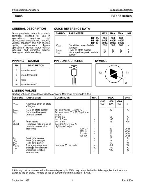
Philips Semiconductors<strong>Triacs</strong>Product specification<strong>BT138</strong> <strong>series</strong>GENERAL DESCRIPTIONQUICK REFERENCE DATAGlass passivated triacs in a plastic SYMBOL PARAMETER MAX. MAX. MAX. UNITenvelope, intended for use inapplications requiring high <strong>BT138</strong>- 500 600 800bidirectional transient and blocking <strong>BT138</strong>- 500F 600F 800Fvoltage capability and high thermal <strong>BT138</strong>- 500G 600G 800Gcycling performance. Typical V DRM Repetitive peak off-state 500 600 800 Vapplications include motor control,voltagesindustrial and domestic lighting, I T(RMS) RMS on-state current 12 12 12 Aheating and static switching. I TSM Non-repetitive peak on-state 95 95 95 AcurrentPINNING - TO220AB PIN CONFIGURATION SYMBOLPIN DESCRIPTION1 main terminal 12 main terminal 2tabT2T13 gatetab main terminal 2123GLIMITING VALUESLimiting values in accordance with the Absolute Maximum System (IEC 134).SYMBOL PARAMETER CONDITIONS MIN. MAX. UNIT-500 -600 -800V DRM Repetitive peak off-state - 500 1 600 1 800 VvoltagesI T(RMS) RMS on-state current full sine wave; T mb ≤ 99 ˚C - 12 AI TSM Non-repetitive peak full sine wave; T j = 25 ˚C prior toon-state currentsurget = 20 ms - 95 AI 2 t I 2 t for fusingt = 16.7 mst = 10 ms--10545AA 2 sdI T /dt Repetitive rate of rise of I TM = 20 A; I G = 0.2 A;on-state current aftertriggeringdI G /dt = 0.2 A/µsT2+ G+ - 50 A/µsT2+ G- - 50 A/µsT2- G-T2- G+--5010A/µsA/µsI GM Peak gate current - 2 AV GM Peak gate voltage - 5 VP GM Peak gate power - 5 WP G(AV) Average gate power over any 20 ms period - 0.5 WT stg Storage temperature -40 150 ˚CT j Operating junction - 125 ˚Ctemperature1 Although not recommended, off-state voltages up to 800V may be applied without damage, but the triac mayswitch to the on-state. The rate of rise of current should not exceed 15 A/µs.September 1997 1 Rev 1.200
Philips Semiconductors<strong>Triacs</strong>Product specification<strong>BT138</strong> <strong>series</strong>THERMAL RESISTANCESSYMBOL PARAMETER CONDITIONS MIN. TYP. MAX. UNITR th j-mb Thermal resistance full cycle - - 1.5 K/Wjunction to mounting base half cycle - - 2.0 K/WR th j-a Thermal resistance in free air - 60 - K/Wjunction to ambientSTATIC CHARACTERISTICST j = 25 ˚C unless otherwise statedSYMBOL PARAMETER CONDITIONS MIN. TYP. MAX. UNIT<strong>BT138</strong>- ... ...F ...GI GT Gate trigger current V D = 12 V; I T = 0.1 AT2+ G+T2+ G---58353525255050mAmAT2- G- - 10 35 25 50 mAI L Latching currentT2- G+ - 22 70 70 100 mAV D = 12 V; I GT = 0.1 AT2+ G+ - 7 40 40 60 mAT2+ G-T2- G---208604060409060mAmAT2- G+ - 10 60 60 90 mAI H Holding current V D = 12 V; I GT = 0.1 A - 6 30 30 60 mAV T On-state voltage I T = 15 A - 1.4 1.65 VV GT Gate trigger voltage V D = 12 V; I T = 0.1 A - 0.7 1.5 VV D = 400 V; I T = 0.1 A; 0.25 0.4 - VI D Off-state leakage currentT j = 125 ˚CV D = V DRM(max) ;T j = 125 ˚C- 0.1 0.5 mADYNAMIC CHARACTERISTICST j = 25 ˚C unless otherwise statedSYMBOL PARAMETER CONDITIONS MIN. TYP. MAX. UNIT<strong>BT138</strong>- ... ...F ...GdV D /dt Critical rate of rise of V DM = 67% V DRM(max) ; 100 50 200 250 - V/µsoff-state voltageT j = 125 ˚C; exponentialwaveform; gate opencircuitdV com /dt Critical rate of change of V DM = 400 V; T j = 95 ˚C; - - 10 20 - V/µscommutating voltage I T(RMS) = 12 A;dI com /dt = 5.4 A/ms; gateopen circuitt gt Gate controlled turn-on I TM = 16 A; V D = V DRM(max) ; - - - 2 - µstimeI G = 0.1 A; dI G /dt = 5 A/µsSeptember 1997 2 Rev 1.200
1Philips Semiconductors<strong>Triacs</strong>Product specification<strong>BT138</strong> <strong>series</strong>Ptot / W20<strong>BT138</strong>Tmb(max) / C95IT(RMS) / A15<strong>BT138</strong>1510= 180120906030102.51101099 C5117.5501250 5 10 15IT(RMS) / AFig.1. Maximum on-state dissipation, P tot , versus rmson-state current, I T(RMS) , where α = conduction angle.0-50 0 50 100 150Tmb / CFig.4. Maximum permissible rms current I T(RMS) ,versus mounting base temperature T mb .ITSM / A1000<strong>BT138</strong>IT(RMS) / A25<strong>BT138</strong>2015100dI /dt limit TT2- G+ quadrantITTITSMtime105Tj initial = 25 C max1010us 100us 1ms 10ms 100msT / sFig.2. Maximum permissible non-repetitive peakon-state current I TSM , versus pulse width t p , forsinusoidal currents, t p ≤ 20ms.00.01 0.1 1 10surge duration / sFig.5. Maximum permissible repetitive rms on-statecurrent I T(RMS) , versus surge duration, for sinusoidalcurrents, f = 50 Hz; T mb ≤ 99˚C.ITSM / A10080<strong>BT138</strong>ITTI TSMtime1.61.4VGT(Tj)VGT(25 C)BT136604020Tj initial = 25 C max1.210.80.601 10 100 1000Number of cycles at 50HzFig.3. Maximum permissible non-repetitive peakon-state current I TSM , versus number of cycles, forsinusoidal currents, f = 50 Hz.0.4-50 0 50 100 150Tj / CFig.6. Normalised gate trigger voltageV GT (T j )/ V GT (25˚C), versus junction temperature T j .September 1997 3 Rev 1.200
Philips SemiconductorsProduct specification<strong>Triacs</strong><strong>BT138</strong> <strong>series</strong>32.52IGT(Tj)IGT(25 C)<strong>BT138</strong>T2+ G+T2+ G-T2- G-T2- G+IT / A40Tj = 125 CTj = 25 C30Vo = 1.175 VRs = 0.0316 Ohms<strong>BT138</strong>typmax1.5201100.50-50 0 50 100 150Tj / CFig.7. Normalised gate trigger currentI GT (T j )/ I GT (25˚C), versus junction temperature T j .00 0.5 1 1.5 2 2.5 3VT / VFig.10. Typical and maximum on-state characteristic.3IL(Tj)IL(25 C)TRIACZth j-mb (K/W)10<strong>BT138</strong>2.51unidirectional2bidirectional1.50.110.01PDt p0.5t0-50 0 50 100 150Tj / CFig.8. Normalised latching current I L (T j )/ I L (25˚C),versus junction temperature T j .0.00110us 0.1ms 1ms 10ms 0.1s 1s 10stp / sFig.11. Transient thermal impedance Z th j-mb , versuspulse width t p .32.52IH(Tj)IH(25C)TRIACdV/dt (V/us)1000100off-state dV/dt limit<strong>BT138</strong>...G SERIES<strong>BT138</strong> SERIES<strong>BT138</strong>...F SERIES1.5110dIcom/dt =15 A/ms 129.175.44.20.50-50 0 50 100 150Tj / CFig.9. Normalised holding current I H (T j )/ I H (25˚C),versus junction temperature T j .10 50 100 150Tj / CFig.12. Typical commutation dV/dt versus junctiontemperature, parameter commutation dI T /dt. The triacshould commutate when the dV/dt is below the valueon the appropriate curve for pre-commutation dI T /dt.September 1997 4 Rev 1.200
Philips Semiconductors<strong>Triacs</strong>Product specification<strong>BT138</strong> <strong>series</strong>MECHANICAL DATADimensions in mmNet Mass: 2 g4,5max10,3max3,71,32,85,9min15,8max3,0 maxnot tinned1,3max(2x)1 2 32,54 2,543,013,5min0,9 max (3x)0,62,4Notes1. Refer to mounting instructions for TO220 envelopes.2. Epoxy meets UL94 V0 at 1/8".Fig.13. TO220AB; pin 2 connected to mounting base.September 1997 5 Rev 1.200
Philips Semiconductors<strong>Triacs</strong>Product specification<strong>BT138</strong> <strong>series</strong>DEFINITIONSData sheet statusObjective specification This data sheet contains target or goal specifications for product development.Preliminary specification This data sheet contains preliminary data; supplementary data may be published later.Product specification This data sheet contains final product specifications.Limiting valuesLimiting values are given in accordance with the Absolute Maximum Rating System (IEC 134). Stress above oneor more of the limiting values may cause permanent damage to the device. These are stress ratings only andoperation of the device at these or at any other conditions above those given in the Characteristics sections ofthis specification is not implied. Exposure to limiting values for extended periods may affect device reliability.Application informationWhere application information is given, it is advisory and does not form part of the specification.© Philips Electronics N.V. 1997All rights are reserved. Reproduction in whole or in part is prohibited without the prior written consent of thecopyright owner.The information presented in this document does not form part of any quotation or contract, it is believed to beaccurate and reliable and may be changed without notice. No liability will be accepted by the publisher for anyconsequence of its use. Publication thereof does not convey nor imply any license under patent or otherindustrial or intellectual property rights.LIFE SUPPORT APPLICATIONSThese products are not designed for use in life support appliances, devices or systems where malfunction of theseproducts can be reasonably expected to result in personal injury. Philips customers using or selling these productsfor use in such applications do so at their own risk and agree to fully indemnify Philips for any damages resultingfrom such improper use or sale.September 1997 6 Rev 1.200