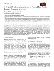
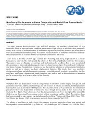
4 <strong>SPE</strong> <strong>146840</strong>Figure 2. Incremental surfactant oil recoveryfrom s<strong>in</strong>gle-well dual-completionFigure 3. IFT reduction around the s<strong>in</strong>gle-well dualcompletiondesign<strong>Pilot</strong> Test Design us<strong>in</strong>g In-house Developed Numerical SimulatorGenerally, dual-porosity model is based on the discrete fracture network (DFN) models. In this model fractures are connectedbut matrices are not. Fracture and matrix can be connected by means <strong>of</strong> transfer function. S<strong>in</strong>ce <strong>in</strong> this model there is nomatrix connection capillary discont<strong>in</strong>uity exists. Because <strong>of</strong> overburden pressures most <strong>of</strong> the horizontal fractures are closedand therefore vertical fractures dom<strong>in</strong>ate the fluid flow <strong>in</strong>side the fractured reservoirs. In these cases one can use dualpermeabilitymodels too. In dual-permeability models matrices are connected and because <strong>of</strong> this connectivity there iscapillary cont<strong>in</strong>uity. This model will result <strong>in</strong> more oil recovery compar<strong>in</strong>g to the dual-porosity model.Case 1: Dual-porosity modelFor a two phase system <strong>in</strong>clud<strong>in</strong>g water and oil follow<strong>in</strong>g f<strong>in</strong>ite-difference forms <strong>of</strong> flow equations is provided:Fracture water material balance,^ P<strong>of</strong>Swf. k f , eff. wf P<strong>of</strong> wD P cw<strong>of</strong> w qwf f Swf c cw ttMatrix water material balance,Pom SwmwmSwm c mcw mttFracture oil material balance,^ P<strong>of</strong>S<strong>of</strong>. k f , eff. <strong>of</strong> P<strong>of</strong> oD o q<strong>of</strong> f S<strong>of</strong> c co ttMatrix oil material balance,Pom SomomSom c mco (4)mttIn dual-porosity formulation transfer function is the rate <strong>of</strong> fluid exchange between fracture and matrix <strong>in</strong> a grid block.Transfer functions for water and oil system are given by z w 0.006328 kmwf / m Po Po w h wf hwm P mcw<strong>of</strong>Pcwom(5) f z m wf fo 0.006328 kmom / fPo Po o h h (6)wmThis formulations account for pressure gradient (viscous force), gravity, and capillarity <strong>in</strong> each local matrix and fracturesystem. A form <strong>of</strong> transfer function which accounts for fluid expansion and molecular diffusion is provided by Ramirez et al.,2009. In contrast with s<strong>in</strong>gle-porosity formulations, fluid exchange <strong>in</strong> a dual-porosity system is based on replacement processrather than displacement. To account for a better fluid displacement <strong>in</strong> dual-porosity models viscous force <strong>in</strong> aboveformulations needs to be adjusted. We have applied this adjustment and we will present the results at the end <strong>of</strong> this paper.Depend<strong>in</strong>g on the flow<strong>in</strong>g phase present, capillary and gravity forces are generally dom<strong>in</strong>ant <strong>in</strong> fractured reservoirs, thereforean approximation form <strong>of</strong> Eq. 5 and Eq. 6 is:wf / m<strong>of</strong> / m z w 0.006328 km P cw<strong>of</strong>Pcwom w oh hwm t wf (1)(2)(3)(7)
<strong>SPE</strong> <strong>146840</strong> 5Eq. 7 is called pseudo transfer function. Us<strong>in</strong>g this form we will have:o (8)wIn Eqs. 5, 6, and 7 the terms <strong>in</strong>side the bracket represent the driv<strong>in</strong>g forces. We have used both forms <strong>of</strong> transfer function <strong>in</strong>dual-porosity formulation. They provide very close results because as po<strong>in</strong>ted before <strong>in</strong> current dual-porosity formulationpressure gradient is negligible. The effects <strong>of</strong> capillary and gravity forces are different from case to case. They can worktogether or can be aga<strong>in</strong>st each other. For example <strong>in</strong> gas <strong>in</strong>jection always gravity difference will play the major role but <strong>in</strong>water flood<strong>in</strong>g both mechanisms might be effective. Add<strong>in</strong>g water and oil material balance equations give global pressureequation, and from that equation implicitly we can obta<strong>in</strong> fracture and matrix pressures. Overall pressure equation is providedby Eq.9:^ P<strong>of</strong>.k f , eff tf P<strong>of</strong> wwf o<strong>of</strong> D wf P cw<strong>of</strong> t qtf fctft(9)Solv<strong>in</strong>g water or oil material balance gives saturation explicitly per time step. To obta<strong>in</strong> saturations <strong>in</strong> matrix either Eq.2 orEq.4 is used. Auxillary equations for this part are given <strong>in</strong> Appendix A.Fracture surfactant material balanceSurfactant concentration per time step can be solved explicitly or implicitly us<strong>in</strong>g Eq. 9. In this equation pressures andsaturations are known at n+1 level. This equation <strong>in</strong>cludes diffusivity term, surfactant participation <strong>in</strong> oil phase, andsurfactant adsorption on the solid phase surface.kf , effwf kf , eff<strong>of</strong>. Cwsf Pwf wD Cwsf P<strong>of</strong> oD wCwsf / moCosf / m BwfB<strong>of</strong> D D ^^ SwfS (10)<strong>of</strong>. S .~ w C wsm S ~ o C osm Cwsf qwf Cosf q<strong>of</strong> f Cwsf Cosf t BwfB 1 f . r.asf <strong>of</strong>m m Eq. 11 accounts for surfactant participitation <strong>in</strong>to oil phase. To account for adsorption we used Longmuir isotherm adsorptionformula. This formulation is provided <strong>in</strong> Appendix B.Cos sCws (11)fMatrix surfactant material balanceSurfactant can penetrate <strong>in</strong>to matrix through transfer function terms; Eq. 12 accounts for this process. Upstream weight<strong>in</strong>gdeterm<strong>in</strong>e whether surfactant goes <strong>in</strong>to or out <strong>of</strong> matrix. In ideal condition surfactant from fracture goes with water transferfunction term. Adsorption is <strong>in</strong>cluded <strong>in</strong> the second part <strong>of</strong> the left right hand side <strong>of</strong> Eq.12. SwmS omwCwsf / m oCosf / m m Cwsm Cosm 1 m . r.asmt BwmBom (12)A conceptual model with the size <strong>of</strong> 10x1x10 grid blocks, with almost the same size <strong>of</strong> the conceptual model <strong>in</strong> CMG, hasbeen built us<strong>in</strong>g three different methods; dual-porosity, dual-permeability, and variable permeability/porosity f<strong>in</strong>e-gridmodel. Implicit-pressure/explicit-saturation (IMPES) formulation is implemented. S<strong>in</strong>gle-well dual-completion method isused <strong>in</strong> this conceptual model with <strong>in</strong>jection rate <strong>of</strong> 30 bbls/day. Surfactant <strong>in</strong>cremental oil recovery was <strong>in</strong>vestigated byus<strong>in</strong>g IFT reduction and wettability alteration methods. Dur<strong>in</strong>g surfactant <strong>in</strong>jection simulator calculates IFT, Capillarynumber or Bond number, residual oil saturation, relative permeability, capillary pressure, fluid heights <strong>in</strong> fracture and matrixnodes. IFT will be calculated based on surfactant concentration. We used two forms <strong>of</strong> Bond number and Capillary number:mkm w oNB . IFT.cosWhere,mw ogravity gradient <strong>in</strong> [psi/ft], m, porosity <strong>of</strong> the matrix,IFT, water-oil <strong>in</strong>terfacial tension <strong>in</strong> [dynes/cm], and cos is contact angle. In addition to use the above formulation, we haveused a comb<strong>in</strong>ation form <strong>of</strong> Capillary number and Bond number <strong>in</strong> the matrix, which gives close results as Bond number.Us<strong>in</strong>g the driv<strong>in</strong>g force <strong>in</strong> pseudo transfer function, we have:Nck is the absolute permeability <strong>of</strong> the matrix [md], 2.262 108 wf wmkmP cw<strong>of</strong>Pcwom w o h hm z. IFT . cos Where, z is matrix block height (ft) <strong>in</strong> z direction. To achieve a Bond number or Capillary number greater than 10-5 , weneed to have a very low IFT, which requires large amount <strong>of</strong> surfactant concentration <strong>in</strong>side the matrix. Our simulationshows that we need to <strong>in</strong>ject a high concentration <strong>in</strong>to the reservoir. Residual oil saturation will be <strong>in</strong>terpolated based on(13)(14)