
Create successful ePaper yourself
Turn your PDF publications into a flip-book with our unique Google optimized e-Paper software.
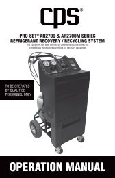
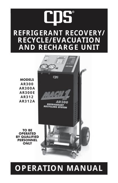
®REFRIGERANT RECOVERY/RECYCLE/EVACUATIONAND RECHARGE UNITMODELSAR300AR300AAR300EAR312AR312ATO BEOPERATEDBY QUALIFIEDPERSONNELONLY<strong>OPERATION</strong> <strong>MANUAL</strong>1
UNIT CONSISTS OF:• AR300 Series Mach 1 Automotive Refrigerant Recovery/Recycling/Evacuation and Recharge MachineEND USER TO PROVIDE:• 2 Stage 6 cfm/142 lpm Vacuum PumpR-12 and R-134a Refrigerant• 50 lbs/27.2 liter Recovery Cylinder OEM specified A/C system oils• All necessary Refrigerant hoses• Low and High Side R-134a Couplings (AR300/AR300A/AR300E)Low and High Side R-12 Service Valves (AR312/AR312A)• Virgin tank transfer adapters (AR300/AR300A/AR300E)• Operation ManualTABLE OF CONTENTSSPECIFICATIONS.................................................. 2INTRODUCTION .................................................... 3GENERAL SAFETY INSTRUCTIONS .................... 4INITIAL EQUIPMENT PREPARATION ................... 5AR300 CONTROL PANEL LAYOUT ....................... 6AR300 REAR LAYOUT ........................................... 7QUICK START GUIDE ........................................... 8AR400 <strong>OPERATION</strong> ........................................... 9-17NON-CONDENSABLE GAS PURGING ................ 18ROUTINE MAINTENANCE ................................ 19-21TROUBLE SHOOTING CHART ............................ 22WARRANTY AND CONTACT INFO. ........... BACK COVERAR300 SPECIFICATIONSDimensions ......................................... 20" (51cm) wide x 30" (76 cm) deepx 50" (127cm) highWeight (w/o tank & vacuum pump) .... 140 lbs (85 kgs)Operating Range ................................ 40°F (4°C ) to 120°F (49°C)Refrigerant .......................................... (AR300/AR300A/AR300E) R-134a............................................................ (AR312/AR312A) R-12Cylinder Capacity ............................... 50 lb recovery tankEmpty Tank Weight* ........................... 27.8 lbs (12.48 kg)Maximum Refrigerant Weight* ........... 38.0 lbs (15.87 kg)Vacuum Pump .................................... 2 stage 6 cfm/142 lpm Vacuum pumpPower Source ..................................... 115 VAC 60Hz (AR300/AR312)............................................................ 220-240 50/60 Hz (AR300A/AR300E/AR300S)Power Consumption ........................... 485 WMoisture Size/Capacity ....................... 650 ccm / 60 ml of waterScale Resolution ................................. 10 g / 0.25 ouncesPressure Gauge .................................. Class1.6*<strong>CPS</strong> SUPPLIED TANKS, FOR OTHER TANKS PLEASE SEE TANK MANUFACTURERS SPECIFICATIONS2
INTRODUCTIONThank you for purchasing the <strong>CPS</strong> Mach 1 AR300 series unit. <strong>CPS</strong> is dedicatedto give you the fastest and most reliable equipment to meet all your mobile A/Cservice requirements. In doing this <strong>CPS</strong> has integrated its latest technology andincorporated state of the art features while improving reliability and speed.The AR300 is a single circuit Refrigerant Handling machine. The AR300 is forR-134a and AR312 is for R-12. The unit automatically recovers, recycles, evacuatesand recharges. Simply hook up the service hoses, choose the operation and allowthe unit to perform its job until it automatically shuts off.The AR300 utilizes a single pass (coalescing and distillation) recycling system,which means that when the AR300 recovers it also recycles. Thus the recoverytank always contains the cleanest refrigerant possible for future use.The Mach 1 AR300 utilizes a 3/4 hp. compressor, non-restrictive control valvesand large ported solenoid valves to make it one of the fastest refrigerant handlingsystems in its class.The AR300 utilizes a unique compressor assist charging method that does notrequire a heater blanket. This gives the unit one of the fastest recharge rates of upto 3.0 lbs/1.5 kg per minute. The unit will even notify you if there is not enoughrefrigerant in the recovery tank to perform the charging operation!THE FOLLOWING ARE ADDITIONAL FEATURES:• Integrated Manifold Gauge Set. Visually see how the mobile A/C system is operating.• A highly accurate electronic charge scale has been integrated into the AR300 controlsystem• Microprocessor Integrated hour meter give the user immediate information on the statusof the moisture filtration system.• Tank overfill protection is provided by the electronic scale software and hardware.• Automatic high-pressure shut-off with microprocessor indicator.• Use your countries approved recovery cylinder. The software allows the user to set up theproper tank and refrigerant parameters.• Modular component design and a hinge front panel allow for easy service access.• Built in Oil and/or Dye vacuum injection with a 16 oz (480 ml) reservoir.• The unit has the ability to recharge large amounts of refrigerants.• One bolt-external filter access system allows the user to change the filter core in less than5 minutes.• Replace only the filter core. This will greatly reduce the maintenance cost of filter changes.• The control valves utilize <strong>CPS</strong>’s fully ported Teflon valves.• Heavy-duty construction, powder coated steel cabinet mounted onto a 1" (2.5 cm) tubularsteel wrap around frame.• 10"/25cm pneumatic rear wheels and 4"/10cm swivel casters give this unit excellentmaneuverability under the worst of conditions.• Recovers and Evacuates through both the high and low side service hoses.• 2 stage, 6cfm vacuum pump for faster evacuationsTo help you get a good start, please continue to carefully read the balance ofthis manual. This manual contains important information on the proper proceduresfor operating this equipment. Please pay close attention to the safety information,WARNINGS, and CAUTIONS provided throughout this manual. ALWAYSREMEMBER “SAFETY FIRST”.3
GENERAL SAFETY INSTRUCTIONSONLY QUALIFIED SERVICE PERSONNEL SHOULD OPERATE THIS UNIT.MOST STATES, COUNTRIES, PROVINCES, ETC... MAY REQUIRETHE USER TO BE LICENSED.PLEASE CHECK WITH YOUR LOCAL GOVERNMENT AGENCY.DANGER - this unit’s recovery tankcontains liquid refrigerant. Overfilling ofthe recovery tank may cause a violentexplosion resulting in severe injury oreven death. Do not disable the overfillsafety features. Always make sure thecorrect tank is on the scale.DANGER - Only use the recovery tankprovided with this unit. See distributorfor replacement tanks.DANGER - Avoid breathing refrigerantvapors and lubricant vapor or mist.Breathing high concentration levelsmay cause heart arrhythmia, loss ofconsciousness, or even causesuffocation.CAUTION - all hoses may contain liquidrefrigerant under pressure. Contact withrefrigerant may cause frostbite or otherrelated injuries. Wear proper personalprotective equipment such as safetygoggles and gloves. Whendisconnecting any hose, please useextreme caution.CAUTION - avoid breathing refrigerantvapors and/or lubricant mist. Exposuremay irritate eyes, nose, throat, and skin.Please read the manufacturers MaterialSafety Data Sheet for further safetyinformation on refrigerants andlubricants.CAUTION - to reduce the risk of fire,avoid the use of extension cords thinnerthan NO. 14 awg. (1,5 mm 2 ) to preventthe overheating of this cord please keeplength to a minimum.CAUTION - do not use this equipmentin the vicinity of spilled or opencontainers of gasoline or otherflammable substances. Make certainthat all safety devices are functioningproperly before operating theequipment.Make sure that recovery tank is placedon the load cell platform at all times.Failure to do so will disable certainsafety features of this unit. The non-usedtank should be placed on its holder.Always disconnect power sourcewhen servicing this equipment.4
INITIAL EQUIPMENT PREPARATION1. Carefully unpackage the AR300.2. Find the box marked “Open Me First”.Open and remove contents.THE CONTENTS ARE AS FOLLOWS:• Red 8 ft R-12 service hose w/high side servicevalve, Blue 8 ft R-12 service hose w/low sideservice valve for AR312 -or-Red 8 ft R-134a service hose w/high sidecouplers, Blue 8 ft R-134a service hose w/lowside couplers for AR300• 8 oz of vacuum pump oil• 6 foot 115 volt power cord• Operation Manual• Two Virgin Tank Adapters (R-134a units only):1/4 SAE x R-134a low side coupler,1/2 ACME x R-134a low side coupler• Two 3/16 Cotter Pins3. Pull the Back Wheel as far as it will move.It should move about 1 1/2". Place theprovided Cotter pin into the hole throughthe axle just behind the wheel hub. Repeatthis procedure for the other side. This willextend the wheelbase to 23".4. Attach the Blue 8 ft service hose w/LowSide Service valve onto the low sidemanifold fitting just below the Low SidePressure Gauge and Valve. Place the LowSide Service valve onto the adapter on theback of the unit for storage.5. Attach the Red 8 ft service hose w/HighSide Service valve onto the high sidemanifold fitting just below the High SidePressure Gauge and Valve. Place the HighSide Service valve onto the adapter on theback of the unit for storage.6. Place the Storage tank onto the center ofthe Scale platform.7. Open both storage tank valves to purgenitrogen from tank before connectinghoses. Connect the vapor hose (fromback of unit) onto the storage tank vaporports. Connect the blue purge hose (fromthe back of the unit) to the auxiliary serviceport on the top of the tank. Make sure thepurge hose is equipped with a Schradercore depressor. Do not hook up with theliquid hose at this time.8. Add oil to the Vacuum Pump. Make surethe vacuum pump power switch is in the“ON” position, the vacuum pump hose isproperly connected and the vacuum pumpvalve is open (if equipped). Also check thatthe vacuum pump power cord is properlyplugged into the receptacle on the backof the unit. Read vacuum pump manualfor further maintenance issues.9. If desired, please add OEM recommendedA/C oil and /or dye to the Oil InjectionBottle. Do not use Oil Injection Valveunless bottle is filled above the 2 oz mark.10.The next step will be to evacuate theAR300 Refrigerant Circuits and StorageTank.5a) Attach the provided power cord to theelectrical inlet. Turn power switch to “I”(On) position.Note: From step 7, open both storage tankvalves to purge nitrogen from tank beforeconnecting hoses. Failure to do this maynot allow the AR300 to operate in theVACUUM mode.b) Connect the Blue service hose to theliquid port on the storage tank. Note: Forthe AR300/AR300A use the 1/4" femaleflare to Low Side R-134a adaptor on theliquid port to properly connect the blueservice coupling. Open all tank valves.c) Push the MODE key. Push the “+” keyuntil Mode 2 “VACUUM” shows up on theLCD. Push the “SET” key to selectVACUUM mode.d) Following the directions on the LCD forthe VACUUM mode. Program theVACUUM time for at least 20 minutes.e) Once the vacuum pump begins tooperate, it should be visually noticed thatmanifold and purge gauges should fallinto a vacuum. Repeat if necessary.f) Once complete, disconnect the servicehose from the purge port. Connect thepurge hose to the purge port on thestorage tank. Make sure it is equippedwith a Schrader core depressor.11.The next step is the procedure to addnew refrigerant to the AR300 recoverytank.a) Turn the power switch to “I” (On) position.b) Push the MODE key. Use the “+” or “-”keys to scroll to Mode 8 REFILL. Push“SET” key.c) Follow directions on LCD. Note: To speedup the refill process, turn the Vigin SupplyTank upside down to make sure thatliquid refrigerant is being recovered. Theunit will automatically shut off at apredetermined level (26.5lbs).d) Once the refill is complete, push the“STOP” key. Check purge gauge fortank pressure.12. The following is how to change thelanguage on the LCD.a) Push the "+" while turning on the powerto the unit. LCD will read:ENGLISHSTOP-NO SET-YESb) If English is your language choice pushthe "SET" key. To scroll to otherlanguages, push the "STOP" key.Congratulations,The Mach1 model AR300 series is nowready for service use.Please refer to the rest of this manualfor proper operating instructions.
AR300 CONTROL PANEL LAYOUT14762 351. Tank Pressure Gauge – used to monitor the R-134a Recovery TankPressure2. Low Side Pressure Gauge and Valve – with Valve closed, measureAuto A/C low side pressure.3. High Side Pressure Gauge and Valve – with Valve closed, used tomeasure Auto A/C high side pressure.4. Purge Switch Power Switch – used to purge NCG’s from R-134aRecovery Tank5. Main Power Switch6. LCD Display – used to instruct and inform the user of the AR300operation7. Key Pad – used to program the operation of the AR300a. MODE Key – input key to start mode selection right afterRefrigerant Selection.b. lb/kg Key – input key to select units of weightmeasurement.c. STOP Key – used as an input key during operation. Canalso be used to abort the operation of the unit while runningin modes 1 through 8. Can also be used to abort during theprogramming sequence.d. + ARROW Key – used as an input key to scroll throughoperational modes. Also used as input key to increaseprogram times and charge weights. Also used to selectrefrigerant mode and other programming selections.e. - ARROW Key – same as + ARROW Key, except reversescroll and decreases program time and charge weight.f. SET Key – used as an input key to select operational mode.Also used as an input key during programming.6
AR300 REAR LAYOUT1615181 56748129111013141. Hose Holders2. Scale or Load Cell3. Recovery Tank4. Fan5. IEC Electrical Connection6. Circuit Breaker7. High Pressure Reset8. Sight glass9. Oil Injector10. Liquid Hose11. Vapor Hose12. Purge Hose13. Vacuum Pump Hose14. Vacuum Pump15. Vacuum Pump Receptacle16. Filter Shell17. Oil Drain Bottle18. Printer Connection17327
QUICK START GUIDEIMPORTANT: Before using this Quick Start Guide it is highlyrecommended that the user completely read and understand this entiremanual. Failure to operate as specified could result in damage to theunit, which could also lead to loss of warranty.• Connect the correct Refrigerant service hoses to the automobile a/c system tobe serviced.• Open the High and Low Side Service Fittings (fittings at the end of the servicehoses).• With the AR300 Manifold valves closed, you can run the automobile a/csystem and determine operating pressures. The unit is equipment withMin/Max gauge indicators.The AR300 is a microprocessor driven unit. Most of the operating instructionsare contained on the LCD. Simply choose the desired function of the unit andfollow the directions on the LCD. The following are the basic keystrokes torun this unit:• Turn the Power switch to “I” (On)position. Open all Tank Valves.• The LCD message should now readPUSH MODE KEYXX LBS XX.XX OZNote: The 2nd line will display thecurrent refrigerant weight in therecovery cylinder. Push “MODE”key.• The LCD screen now reads1 RECOVER/RECYCLE- +Push the “+” or “-” keys to scrollthrough the different modes. Oncethe desired operation is displayed,push the “SET” key.THE DIFFERENT MODES AREAS FOLLOWS:1. Mode 1 – Recovery/Recycle2. Mode 2 – Vacuum/Injection3. Mode 3 – Charge4. Mode 4 – Full Cycle5. Mode 5 – Vacuum/Charge6. Mode 6 – Quick Charge7. Mode 7 – Liquid Flush8. Mode 8 – Refill9. Mode 9 – MaintenanceA. Mode 9A - Air PurgeB. Mode 9B - Filter ChangeC. Mode 9C - Re-zero scaleD. Mode 9D - RefrigerantManagementFollow the directions on the LCD foreach mode. The following pages willdiscuss each Mode.8
AR300 <strong>OPERATION</strong> MODESSTART UPTurn Main Power Switch to the “ON”position. A few diagnostic messagesmay appear. After about 5 seconds theLCD will read:CURRENT FILTERLIFE 3000 MINSAfter a few more seconds, the LCDmessage now reads:PUSH MODE KEYXX LBS XX.XX OZNote: The 2nd line will display thecurrent refrigerant weight in therecovery cylinder. If metric weights arerequired, push the “LB/KG” key to selectunits of measure.Push “MODE” key.The LCD screen now reads:1 RECOVER/RECYCLE- +Push the “+” or “-” keys to scrollthrough the different modes. Once thedesired operation is displayed, push the“SET” key.MODE 1. – RECOVER/RECYCLEThe Recover/Recycle mode would bechosen to recovery refrigerant from anAuto A/C system that needs a refrigerantcontaining component replaced suchas a compressor, evaporator, orificetube, condenser, etc....When LCD screen reads:1 RECOVER/RECYCLE- +Push the “SET” key. The LCD will nowread:OPEN HI & LO MNFDVALVES. PUSH STARTPush the “START” key. The LCD willnow read:1 RECOVERINGXX LBS XX.XX OZThe AR300 is now recoveringrefrigerant. The 2nd LCD line recordsthe amount of refrigerant recovered.When the AR300 reaches the EPArequired vacuum level, the LCD willread: 90 sec time delay for gasing.1 DONE PUSH STOPXX LBS XX.XX OZPush “STOP” to return to RefrigerantSelection Screen. Do not forget tomeasure the A/C oil in the oil drain bottlefor future re-injection.MODE 1 RECOVER/RECYCLE is nowcomplete.9
AR300 <strong>OPERATION</strong> MODESMODE 2. – VACUUM/INJECTIONThe VACUUM/INJECTION Mode wouldbe chosen to remove air and moisturefrom an Auto A/C system that has beenopen to atmosphere.Scroll until the LCD screen reads:2 VACUUM/INJECTN- +Push the “SET” key. The LCD will nowread:OPEN HI & LO MNFDVALVES. PUSH STARTPush the “START” key. The LCD will nowread:SELECT VAC TIMEUSE+ or -KEYSPush the “+ “ or “-” key until the desiredvacuum time is programmed.XXX MINPUSH SETPush the “SET” key. The LCD will nowread:RUN VAC HLD TIME?YES+ NO-The Vacuum Hold Time is a feature tosee if the A/C system will hold a vacuumover a programmed amount of time.This feature can be bypass by push “-”key. Once the “-” key is pushed, theVACUUM /INJECTION Mode will begin.If “+” key pushed the LCD will now read:SELECT VAC HLD TIMEUSE+ or -KEYSPush the “+” or “-” key until the desiredvacuum hold time is programmed:Push the “START” key to start theVACUUM /INJECTION Mode.During this Mode the LCD timer willcount down the remaining Evacuationtime.When the timer reaches zero, theEvacuation Mode will end and the LCDwill now read:Push the “STOP” key.OPTION 1.XXX MINPUSH SET2 VACUUMING A/CXX:XX TO GO2 VACUUM DONEPUSH STOPIf the Vacuum Hold feature wasprogrammed, the LCD will read:READ AND RECORDVAC LEVEL PUSH SETPush SET key, the LCD will read:4 VAC HOLD TIMEXX:XX TO GO10
AR300 <strong>OPERATION</strong> MODESWhen the Vacuum Hold time reacheszero, the LCD will read:READ AND RECORDVAC LEVEL PUSH SETIf the Vacuum Level is maintained, pushthe “SET” key. When the SET key ispushed, the LCD will read the messagebelow and continue with MODE 2operation. If Vacuum Level is lost, pushthe STOP key twice to abort this Mode.Find leak and try again.The LCD will now read:READY FOR <strong>MANUAL</strong>INJECT PUSH STOPInject A/C oil back into the mobileA/C at this time. This must be followedup by the CHARGE Mode to allow theliquid refrigerant to carry the injectedoil back to the A/C.Push the “STOP” key. The LCD willreturn to the Refrigerant SelectionScreen.MODE 2 VACUUM/INJECTION is nowcomplete.MODE 3. – CHARGE MODEThe CHARGE would be chosen torecharge a mobile A/C system after ithas been properly evacuated. NOTE: Airand/or moisture in an A/C system cancause premature failure of A/C systemcomponents.Scroll until the LCD screen reads:3 CHARGE- +Push the “SET” key. The LCD will nowread:OPEN HI & LO MNFDVALVES. PUSH STARTPush the “SET” key. The LCD will nowread:USE+ or -KEYSSELECT CHARGE WGPush the “+ “ or “-” key until the desiredcharge amount is programmed.XX kgXXXgPUSH STARTPush the “START” key to start theCHARGE Mode. During this Mode theLCD will display the amount charged.3 CHARGINGXX kg XXXgOnce the amount displayed equals thecharged amount, the LCD will read:3 DONE PUSH STOPXX kg XXXg11Push the “STOP” key. The LCD willreturn to the Refrigerant SelectionScreen.MODE 3 CHARGE is now complete.
AR300 <strong>OPERATION</strong> MODESMODE 4. – FULL CYCLEThe FULL CYCLE is commonly used atquick lube facilities where no leaks orrepairs are required, but the A/C systemseems to be undercharged.Scroll until the LCD screen reads:If “+” key pushed the LCD will now read:SELECT VAC HLD TIMEUSE+ or -KEYSPush the “+” or “-” key until the desiredvacuum hold time is programmed:3 CHARGE- +XXX MINPUSH SETPush the “SET” key. The LCD will nowread:OPEN HI LO MNFDVALVES. PUSH STARTPush the “START” key. The LCD willnow read:SELECT VAC TIMEUSE+ or -KEYSPush the “+ “ or “-” key until the desiredvacuum time is programmed.XXX MINPUSH SETPush the “SET” key. The LCD will nowread:RUN VAC HLD TIME?YES+ NO-The Vacuum Hold Time is a feature tosee if the A/C system will hold a vacuumover a programmed amount of time.This feature can be bypass by push “-”key. If the “-” key is pushed go to RUNOIL INJECTION screen below.Push the “SET” key or the “-” key fromabove, the LCD will read:RUN OIL INJECTN?YES+ NO-The OIL INJECTION feature during theFULL CYCLE mode is used to allow theuser to interrupt the full cycle operationright after vacuum to inject oil back intothe A/C system. If the “+” key ispushed, the unit will notify the user whenit is time to inject oil. This feature canalso be bypass by push “-” key.Push either the “+” or “-” key toprogram this feature. The LCD displaywill now read:USE+ or -KEYSSELECT CHARGE WGPush the “+ “ or “-” key until the desiredcharge amount is programmed.XX kgXXXgPUSH STARTPush the “START” key to start the FULLCYCLE Mode. The LCD will now read:1 RECOVERINGXX LBS XX.XX OZThe AR300 is now recoveringrefrigerant. The 2nd LCD line recordsthe amount of refrigerant recovered.12
AR300 <strong>OPERATION</strong> MODESWhen the AR300 reaches the EPArequired vacuum level, the unit willswitch to Vacuuming (if vacuum timeprogrammed)During the vacuum operation the LCDtimer will count down the remainingEvacuation time.4 VACUUMING A/CXX:XX TO GOWhen the timer reaches zero, theVacuum operation will end. There aretwo different options that could beprogrammed. If these options werenot programmed, proceed to chargefunction of this mode.OPTION 1.If the Vacuum Hold feature wasprogrammed, the LCD will read:READ AND RECORDVAC LEVEL PUSH SETPush SET key, the LCD will read:4 VAC HOLD TIMEXX:XX TO GOOPTION 2.If the Vacuum Hold feature wasprogrammed, the LCD will read:READY FOR <strong>MANUAL</strong>INJECT PUSH STOPIf required, inject A/C oil back into themobile A/C at this time.Push the STOP key.Once either or both options, have beencompleted, the unit will proceed into thecharge function of this mode.The LCD will read:4 CHARGINGXX kg XXXgOnce the amount displayed equals thecharged amount, the LCD will read:4 DONE PUSH STOPXX kg XXXgPush the “STOP” key. The LCD willreturn to the Refrigerant SelectionScreen.MODE 4 FULL CYCLE is now complete.When the Vacuum Hold time reacheszero, the LCD will read:READ AND RECORDVAC LEVEL PUSH SETIf the Vacuum Level is maintained, pushthe “SET” key. When the SET key ispushed the unit will Either go intoOption 2 if programmed or begin theCharge operation. If Vacuum Level islost, push the "STOP" key twice to abortthis mode. Find leak and try again.13
AR300 <strong>OPERATION</strong> MODESMODE 5. – VACUUM/INJECTION/CHARGEThe Vacuum/Injection/Charge iscommonly used to complete a serviceon an Auto A/C system that had arefrigerant containing componentreplaced such as a compressor,evaporator, orifice tube, condenser,etc....or other service that would haveopen the system to the atmosphere.This mode is the same as Mode 4,except it does not perform the recoveryfunction.IMPORTANT NOTE: DO NOT RUNTHIS MODE IF MORE THAN 5 PSIGPRESSURE IS PRESENT IN THEAUTO A/C SYSTEM. THIS MODEOVERRIDES THE VACUUM SWITCHTHAT PREVENTS OPERATING THEVACUUM PUMP IF PRESSUREEXISTS IN AN A/C SYSTEM.Scroll until the LCD screen reads:5 VAC/INJ/CHARGE- +Push the “SET” key. The LCD will nowread:OPEN HI & LO MNFDVALVES. PUSH STARTPush the “START” key. The LCD willnow read:SELECT VAC TIMEUSE+ or -KEYSPush the “+ “ or “-” key until the desiredvacuum time is programmed.XXX MINPUSH SETPush the “SET” key. The LCD will nowread:RUN VAC HLD TIME?YES+ NO-The Vacuum Hold Time is a feature tosee if the A/C system will hold a vacuumover a programmed amount of time.This feature can be bypass by push “-”key. If the “-” key is pushed, go to RUNOIL INJECTION screen below.If “+” key pushed the LCD will now read:SELECT VAC HLD TIMEUSE+ or -KEYSPush the “+” or “-” key until the desiredvacuum hold time is programmed:XXX MINPUSH SETPush the “SET” key or the “-” key fromabove, the LCD will read:RUN OIL INJECTN?YES+ NO-The OIL INJECTION feature during thismode is used to allow the user tointerrupt the mode 5 operation right aftervacuum to inject oil back into the A/Csystem. If the “+” key is pushed, theunit will notify the user when it is time toinject oil. This feature can also bebypass by push “-” key.Push either the “+” or “-” key toprogram this feature. The LCD displaywill now read:USE+ or -KEYSSELECT CHARGE WGPush the “+ “ or “-” key until the desiredcharge amount is programmed.XX kgXXXgPUSH START14
AR300 <strong>OPERATION</strong> MODESPush the “START” key to start theVACUUM/INJECTION/CHARGE Mode.The LCD will now read:5 VACUUMING A/CXX:XX TO GOWhen the timer reaches zero, theVacuum operation will end. There aretwo different options that could beprogrammed. If these options werenot programmed proceed to chargefunction of this mode.OPTION 2.If the Vacuum Hold feature wasprogrammed, the LCD will read:READY FOR <strong>MANUAL</strong>INJECT PUSH STOPIf required, inject A/C oil back into themobile A/C at this time.Push the STOP key.OPTION 1.If the Vacuum Hold feature wasprogrammed, the LCD will read:READ AND RECORDVAC LEVEL PUSH SETPush SET key, the LCD will read:5 VAC HOLD TIMEXX:XX TO GOWhen the Vacuum Hold time reacheszero, the LCD will read:READ AND RECORDVAC LEVEL PUSH SETIf the Vacuum Level is maintained, pushthe “SET” key. When the SET key ispushed the unit will either go into Option2 if programmed or begin the Chargeoperation. If Vacuum Level is lost, pushthe "STOP" key twice to abort this mode.Find leak and try again.Once either or both options, have beencompleted, the unit will proceed into thecharge function of this mode.The LCD will read:5 CHARGINGXX kg XXXgOnce the amount displayed equals thecharged amount, the LCD will read:5 DONE PUSH STOPXX kg XXXgPush the “STOP” key. The LCD willreturn to the Refrigerant SelectionScreen.MODE 5 VAC/INJ/CHARGE is nowcomplete.15
AR300 <strong>OPERATION</strong> MODESMODE 6. – QUICK CHARGE MODEThe QUICK CHARGE would be chosento top off an A/C system. The auto a/csystem needs to be running to performthis function.Scroll until the LCD screen reads:6 QUICK CHARGE- +Push the “SET” key. The LCD will nowread:CLOSE HI & LO MNFDVALVES. PUSH SETPush the “SET” key. The LCD will nowread:START AUTO A/CSYSTEM. PUSH SETPush the “SET” key. The LCD will nowread:USE+ or -KEYSSELECT CHARGE WGPush the “+ “ or “-” key until the desiredcharge amount is programmed.XX kgXXXgPUSH STARTPush the “START” key to start theQUICK CHARGE Mode. During thisMode the LCD will display the amountcharged.OPEN LO MNFLD VLVEXX kg XXXgOnce the amount displayed equals thecharged amount, the LCD will read:6 CHARGE COMPLETE-REPEAT +STOPIf the “-” key is pushed, this operationwill be repeated.If the “+” key is pushed, the LCD willreturn to the Refrigerant SelectionScreen.MODE 6 is now complete.MODE 7. – LIQUID FLUSHThe LIQUID FLUSH would be chosento flush the compressor oil from an AutoA/C system. This is usually done whenretrofitting a car from R-12 to R-134a oranother alternate refrigerant. Whenflushing, always use the refrigerant typecontained in the Auto A/C system.Scroll until the LCD screen reads:7 LIQUID FLUSH- +Push the “SET” key. The LCD will nowread:OPEN HI & LO MNFDVALVES. PUSH STARTPush the “SET” key. The LCD will nowread:USE+ or -KEYSSELECT FLUSH TIMEPush the “+ “ or “-” key until the desiredcharge amount is programmed.XXX MINPUSH SETPush the “SET” key. The LCD will nowread7 READY TO FLUSHPUSH STARTPush the “START” key to start theLIQUID FLUSH Mode. During this Modethe LCD will display the amount ofFLUSH TIME remaining.16
AR300 <strong>OPERATION</strong> MODES7 FLUSHINGXX:XX TO GOWhen the timer reaches zero, theLIQUID FLUSH cycle will end and theLCD will now read:7 RECOVERINGPLEASE WAITThe unit could take up to 45 minutes torecover the refrigerant used in flush.Please wait until LCD reads:7 FLUSH DONEPUSH STOPPush the “STOP” key. The LCD willreturn to the Refrigerant SelectionScreen.MODE 7 LIQUID FLUSH is nowcomplete.MODE 8. – REFILL MODEThe REFILL Mode would be chosen toadd more refrigerant to the recoverytank. This mode could be prompteddirectly from Mode 3,4, or 5.Scroll until the LCD screen reads:8 REFILL- +Push the “SET” key. The LCD will nowread:OPEN LO MNFD VALVE.PUSH SETPush the “SET” key. The LCD will nowread:TO NEW REFRIGERANTTANK. PUSH STARTFor R-134a it will be necessary to usethe enclosed adaptor(s) to connect tothe New Refrigerant Tank.Push the “START” key to start theREFILL Mode. During this Mode theLCD will display the total refrigerantamount in the recovery tank. The unitwill run the REFILL mode until one ofthe two conditions occur:8 REFILL DONEPUSH STOPOR7 NEW TANK EMPTYPUSH STOPIf REFILL DONE condition occurs, thatmeans the recovery tank has been fillto 70% of the Maximum Refrigerantamount allowed in the recoverytank (26lbs).If NEW TANK EMPTY condition occurs,repeat this mode with a full NewRefrigerant Tank attached. The previousone is empty.Push the “STOP” key. The LCD willreturn to the Refrigerant SelectionScreen.MODE 8 REFILL MODE is nowcomplete.Push the “SET” key. The LCD will nowread:CONNECT LO SERVICEHOSE. PUSH SET17
NON-CONDENSABLE GAS PURGEMODE 9. – MAINTENANCE MODEThe MAINTENANCE Mode is brokendown into 4 maintenance procedures:1- Air purge, 2- Filter Change, 3- Re-zeroScale, 4- Refrigerant Management.Please read the following to discusseach procedure.Scroll until the LCD screen reads:9 MAINTENANCE- +Push “SET” key. The LCD will now read:A AIR PURGE- +Push the “+” or “-” keys to scrollthrough the different Maintenancemodes.MODE 9A. Air PurgeMODE 9B. Filter ChangeMODE 9C. Re-zero scaleMODE 9D. Refrigerant ManagementOnce the desired operation is displayed,push the “SET” key.MODE 9A. AIR PURGEThe AIR PURGE maintenance mode isused to remove Non-CondensableGases (NCG’s) from the recovery tank.It is best to check in the morning or aftera long period of non-operation. This willallow the refrigerant to stabilize.Scroll until the LCD screen reads:9 MAINTENANCE- +Scroll again until the LCD screen reads:A AIR PURGE- +Push the “SET” key. The LCD will nowread:R-134a TEMP XX.X FR-134a PRESS XXX.X PSIGCompare the LCD pressure reading withthe R-134a tank pressure gauge on thecontrol panel. If the Tank pressuregauge is higher than the LCD reading,hold down the AIR PURGE switch (onthe control panel) until the gaugepressure falls below the LCD reading.Push the “STOP” key. The LCD willreturn to the Refrigerant SelectionScreen.MODE 9A AIR PURGE is now complete.18
ROUTINE MAINTENANCEMODE 9B. FILTER CHANGEThe FILTER CHANGE maintenancemode is used to change the solid corefilter drier. You will need to purchase anARXF filter from your <strong>CPS</strong> distributor.When the filter time has expired, the unitwill need its filter replaced. The FILTERTIME is displayed when selecting theRefrigerant operation. The expected lifeof the filter is 3000 minutes (50 hours).Scroll until the LCD screen reads:9 MAINTENANCE- +Scroll again until the LCD screen reads:B FILTER CHANGE- +Push the “SET” key. The LCD will nowread:OPEN HI & LO MNFDVALVES. PUSH STARTNote: The unit should not be connectedto an Auto A/C system.Once a vacuum has been achieved theLCD will now read:REMOVE FILTER COVERPUSH SETSee Figure 1aPush the “SET” key. The LCD will nowread:REMOVE & REPLACEFILTER. PUSH SETSee Figure 1b and 1cPush the “SET” key. The LCD will nowread:FILTER CHANGEDONE. PUSH STOPPush the “STOP” key. This will reset thefilter time back to 3000 minutes. TheLCD will return to the RefrigerantSelection Screen.MODE 9B FILTER CHANGE is nowcomplete.Push the “START” key. The LCD willnow read:RECOVERINGPLEASE WAITFigure 1a Figure 1b Figure 1c19
ROUTINE MAINTENANCEMODE 9C. RE-ZERO SCALEThe RE-ZERO SCALE maintenancemode is used to tare the scale. Thisshould be done about every 2 monthsto maintain accurate refrigerant weightin the recovery tank.Scroll until the LCD screen reads:Scroll again until the LCD screen reads:Push the “SET” key. The LCD will nowread:REMOVE TANK.PUSH SETPhysically remove tank from scale.Push the “SET” key. The LCD will brieflyread:RESETTING ZEROPLEASE WAITThen:9 MAINTENANCE- +C RE-ZERO SCALE- +REPLACE TANK.PUSH STOPPush the “STOP” key. The LCD willreturn to the Refrigerant SelectionScreen. MODE 9C RE-ZERO SCALE isnow complete.IMPORTANT: Please check to see if theunit needs to be re-zeroed by returning tothe “PUSH MODE” screen. The 2nd linewill give the user the amount of refrigerantcontained in the recovery tank. Byremoving the recovery tank from the scale,the weight reading should be the emptytank weight. For the AR300 this will be 27lbs 8 oz (Note: a negative sign will proceedreading). If this reading is off by ± 8ounces, please repeat Mode 9C.MODE 9D.REFRIGERANT MANAGEMENTThe REFRIGERANT MANAGEMENTmaintenance mode is used to keeptrack of the refrigerant used by thisequipment. There are 3 basic categorieson how refrigerant is used by thismachine: 1-amount recovered,2- amount charged, and 3- amount newrefrigerant added.Scroll until the LCD screen reads:9 MAINTENANCE- +Scroll again until the LCD screen reads:D REF MANAGMENT- +Push the “SET” key. The LCD will nowread:TOTAL 134 RECOVERDXXLB XX.XXOZPush the “SET” key. The LCD will nowread:TOTAL 134 CHARGEDXXLB XX.XXOZPush the “SET” key. The LCD will nowread:TOTAL 134 REFILLEDXXLB XX.XXOZPush the “SET” key. The LCD will nowread:RESET DATA?YES+ NO-Push the “-” key to save the data or pushthe “+” key to reset the data to zero.The LCD will return back to theRefrigerant Selection Screen.20
OTHER ROUTINE MAINTENANCE ISSUESVACUUM PUMP OIL - the Mach 1 AR300 is equipped with an external vacuumpump. It will be necessary to occasionally add additional vacuum pump oil. Viewthe oil level through the sight glass provided on the vacuum pump.If it is noticed that the vacuum pump is not performing as it did when new, completelydrain and refill with new vacuum pump oil. Contaminants in the vacuum pump oilwill greatly affect the performance.Use the recommended vacuum pump oil. Please read the vacuum pump operationmanual for further maintenance details.Periodically change the vacuum pump oil periodically. A good flag would bewhenever the filter(s) are changed, also change the vacuum pump oil.COMPRESSOR OIL - the compressors used in the AR300 are equipped withautomatic oil return systems. No compressor oil maintenance should be required.The oil used on the AR312/AR312A is 3GS mineral oil. The oil used on theAR300/AR300A is PAG oil. Additional amounts can be added directly to thecompressor suction port (refrigerant hose connection point).END OF THE DAY MAINTENANCE - as a matter of precaution, close all recoverytank valves at the end of the day. Close all other valves.Please note that <strong>CPS</strong> does not take responsibility for lost refrigerant.REPLACEMENT GAUGES & PARTS54-100 / 16 Ounce Plastic Oil Bottle30-736 / AR300 High Side Manifold Gauge30-737 / AR300 Low Side Manifold Gauge30-743 AR300E High Side Gauge30-744 AR300E Low Side Gauge74-092 / R-12 Tank Label74-093 / R-134a Tank Label74-099 / Tank ThermometerREPLACEMENT HOSESARH6-A1 / AR300E Low Side Hose 1/4"ARH7-A1 / AR300E High Side Hose 1/4"ARH11-A1 / Tank Hose R-12 1/4"ARH13-A1 / Vacuum Pump HoseARH16-A1 / Low Side Hose R-12ARH17-A1 / High Side Hose R-12VACUUM PUMP OILVPXOQ - quartsVPXOG - gallonsARH27-A1 / AR300/R-134a 8' Low Hose 1/2" acmeARH28-A1 / AR300/R-134a 8' High Hose 1/2" acmeARH29-A1 / AR300 R-134a Tank Hose 1/2" acmeRECOVERY TANKS & FILTERSARXC -AR300 Nylon CoverARXF-AR300 filterAR134T-R-134 1/2" acme recovery tank 50 lb.CRX350T-R-12 1/4" SAE recovery tank 50 lb.CRX390T - High Capacity Recovery Tank 90 lb.T27L-AR300E 27 Liter Recovery TankR-134a SERVICE COUPLERSQCL14-R-134a Low Coupler 1/4"QCH14-R-134a High Coupler 1/4"QCL134-R-134a Low Coupler 14mmQCH134-R-134a High Coupler 14mmPRINTERSARXP115-AR300/Printer with cableARXP220 - AR300 Printer with cable 220 VAC21
TROUBLE SHOOTING CHARTPROBLEM: The unit will only pull down to 0 pressure or a slight vacuum.SOLUTION: Make sure the Oil Injection Valve is fully closed. If left open in theduring the recovery operation, air will be pulled through the valve.SOLUTION: Make sure that both the Low and High Side Service Hoses are leaktight.PROBLEM: THE unit fails to charge the automobile. Message on LCD willread “CHECK CONNECTIONS”.SOLUTION: Make sure that both tank valves are open. Also check that the liquidhose is connected to the liquid port of the tank. Check in-line ballvalves on tankhoses.SOLUTION: Make sure the High and Low Service valves are open.PROBLEM: Weight inaccuracies.SOLUTION: Do not move the unit when operating in the Recovery or Charge Mode.Moving the unit during operation will cause weight reading inaccuracies.SOLUTION: Make sure the recovery tank is not touching the metal railing or backpanel.PROBLEM: In modes 3, 4,5,and 6 after pushing the START key the LCD reads“LOW REFRIGERANT” and will not charge.SOLUTION: The unit’s refrigerant tank needs to contain a minimum of 2.5 lbs plusthe charge amount before charging. Use the refill procedure (Mode 8) to addadditional refrigerant to the recovery tank.PROBLEM: During mode 1,3,4,5,7 or 8 operation the unit is shut-off by thehigh-pressure switch. This should be noted by the LCD message “HIGHPRESSURE LIMIT”.SOLUTION: Make sure that both tank valves are open. Check in-line ballvalves ontank hoses. Push the HPCO reset button to reset unit.PROBLEM: During mode 1,4 or 7 the unit is shut-off by tank overfill safetysystem. The LCD message “TANK FULL” will note this condition.SOLUTION: It will be necessary to charge approximately 5-10 lbs. into an emptyrefrigerant cylinder. Connect the High Side Service valve to the tank liquid portand the Low Side Service valve to the tank vapor port. Follow the directions formode 3 CHARGE.22
WARRANTY & REPAIR POLICY<strong>CPS</strong> guarantees that the MACH 1 is free of manufacturing and materialdefects for two year. If a component should fail during the guarantee periodit will be repaired or replaced (at our option) at no charge. This guaranteedoes not apply to components that have been altered, misused, or returnedsolely in need of field service maintenance. This repair policy does notinclude components that are determined to be beyond economical repair.A component being returned for warranty repair must be accompanied byan original bill of sale and customer contact information.The load cell assembly is guaranteed for two year period.This equipment has been certifiedby ETL/ITS to meet or exceedSAE J2210,J2099 (AR300)and SAE J1991, J1990 (AR312)and UL 1963<strong>CPS</strong> PRODUCTS, INC.1010 East 31st Street, Hialeah, Florida 33013, USATEL: (305) 687-4121, 1-800-277-3808 (U.S. only)FAX: (305) 687-3743<strong>CPS</strong> PRODUCTS N.V.Krijgsbaan 241, 2070 Zwijndrecht, Antwerpen, BelgiumTEL: (32.3) 281 30 40, FAX: (323) 281 65 83<strong>CPS</strong> AUSTRALIA PTY. LTD.Unit 2, 265 Richmond Road, Richmond, SA 5033, AustraliaTEL: 08 8354 0790, FAX: 08 8354 0789<strong>CPS</strong> ASIARuby Industrial Complex #05-09A Genting Block 80 Genting Lane,Singapore 349565TEL: (65) 8461056, FAX: (65) 846105424#73-019 RevC