Elastic relaxation and correlation of local strain gradients with ...
Elastic relaxation and correlation of local strain gradients with ...
Elastic relaxation and correlation of local strain gradients with ...

You also want an ePaper? Increase the reach of your titles
YUMPU automatically turns print PDFs into web optimized ePapers that Google loves.
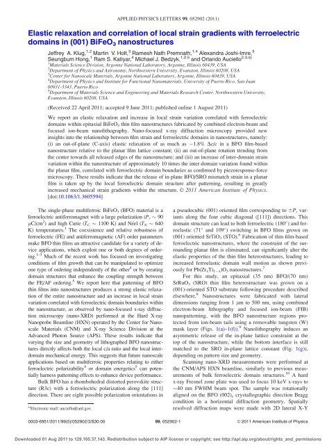
APPLIED PHYSICS LETTERS 99, 052902 (2011)<strong>Elastic</strong> <strong>relaxation</strong> <strong>and</strong> <strong>correlation</strong> <strong>of</strong> <strong>local</strong> <strong>strain</strong> <strong>gradients</strong> <strong>with</strong> ferroelectricdomains in (001) BiFeO 3 nanostructuresJeffrey A. Klug, 1,2 Martin V. Holt, 3 Ramesh Nath Premnath, 1,4 Alex<strong>and</strong>ra Joshi-Imre, 3Seungbum Hong, 1 Ram S. Katiyar, 4 Michael J. Bedzyk, 1,2,5 <strong>and</strong> Orl<strong>and</strong>o Auciello 2,3,a)1 Materials Science Division, Argonne National Laboratory, Argonne, Illinois 60439, USA2 Department <strong>of</strong> Physics <strong>and</strong> Astronomy, Northwestern University, Evanston, Illinois 60208, USA3 Center for Nanoscale Materials, Argonne National Laboratory, Argonne, Illinois 60439, USA4 Department <strong>of</strong> Physics <strong>and</strong> Institute for Functional Nanomaterials, University <strong>of</strong> Puerto Rico, San Juan00931-3343, Puerto Rico5 Department <strong>of</strong> Materials Science <strong>and</strong> Engineering <strong>and</strong> Materials Research Center, Northwestern University,Evanston, Illinois 60208, USA(Received 22 April 2011; accepted 9 June 2011; published online 1 August 2011)We report an elastic <strong>relaxation</strong> <strong>and</strong> increase in <strong>local</strong> <strong>strain</strong> variation correlated <strong>with</strong> ferroelectricdomains <strong>with</strong>in epitaxial BiFeO 3 thin film nanostructures fabricated by combined electron-beam <strong>and</strong>focused ion-beam nanolithography. Nano-focused x-ray diffraction microscopy provided newinsights into the relationship between film <strong>strain</strong> <strong>and</strong> ferroelectric domains in nanostructures, namely:(i) an out-<strong>of</strong>-plane (C-axis) elastic <strong>relaxation</strong> <strong>of</strong> as much as 1.8% Dc/c in a BFO film-basednanostructure relative to the planar film lattice constant; (ii) an out-<strong>of</strong>-plane rotation trending fromthe center towards all released edges <strong>of</strong> the nanostructure; <strong>and</strong> (iii) an increase <strong>of</strong> inter-domain <strong>strain</strong>variation <strong>with</strong>in the nanostructure <strong>of</strong> approximately 10 times the inter-domain variation found <strong>with</strong>inthe planar film, correlated <strong>with</strong> ferroelectric domain boundaries as confirmed by piezoresponse-forcemicroscopy. These results indicate that the release <strong>of</strong> in-plane BFO/SRO mismatch <strong>strain</strong> in a planarfilm is taken up by the <strong>local</strong> ferroelectric domain structure after patterning, resulting in greatlyincreased mechanical <strong>strain</strong> <strong>gradients</strong> <strong>with</strong>in the structure. VC 2011 American Institute <strong>of</strong> Physics.[doi:10.1063/1.3605594]The single-phase multiferroic BiFeO 3 (BFO) material is aferroelectric antiferromagnet <strong>with</strong> a large polarization (P r 90lC/cm 2 ) <strong>and</strong> high Curie (T C 1100 K) <strong>and</strong> Néel (T N 640K) temperatures. 1 The coexistence <strong>and</strong> relative robustness <strong>of</strong>ferroelectric (FE) <strong>and</strong> antiferromagnetic (AF) order parametersmake BFO thin films an attractive c<strong>and</strong>idate for a variety <strong>of</strong> deviceapplications, which exploit one or both degrees <strong>of</strong> ordering.1–3 Much <strong>of</strong> the recent work has focused on investigatingconditions <strong>of</strong> film growth that can be manipulated to optimizeone type <strong>of</strong> ordering independently <strong>of</strong> the other 4 or by creatingdomain structures that enhance the coupling strength betweenthe FE/AF ordering. 5 We report here that patterning <strong>of</strong> BFOthin films into nanostructures produces a strong elastic <strong>relaxation</strong><strong>of</strong> the entire nanostructure <strong>and</strong> an increase in <strong>local</strong> <strong>strain</strong>variation correlated <strong>with</strong> ferroelectric domain boundaries <strong>with</strong>inthe nanostructure, as observed by nano-focused x-ray diffractionmicroscopy (nano-XRD) performed at the Hard X-rayNanoprobe Beamline (HXN) operated by the Center for NanoscaleMaterials (CNM) <strong>and</strong> X-ray Science Division at theAdvanced Photon Source (APS). These results indicate thatvarying the size <strong>and</strong> geometry <strong>of</strong> lithographed BFO nanostructuresdirectly affects both the <strong>local</strong> c/a ratio <strong>and</strong> the <strong>local</strong> interdomainmechanical energy. This suggests that future nanoscaleapplications based on multiferroic properties relating to eitherferroelectric polarizability 4 or domain energetics 5 can potentiallyharness patterning effects to enhance device performance.Bulk BFO has a rhombohedral distorted perovskite structure(R3c) <strong>with</strong> a ferroelectric polarization along the [111]direction. There are eight possible polarization orientations ina) Electronic mail: auciello@anl.gov.a pseudocubic (001) oriented film corresponding to 6P r variantsalong the four cubic diagonal ([111]) directions. Thisdomain structure can lead to both ferroelectric (180 ) <strong>and</strong> ferroelastic(71 <strong>and</strong> 109 ) switching in BFO films grown on(001) oriented SrTiO 3 (STO). 6 Fabrication <strong>of</strong> thin film-basedferroelectric nanostructures, where the con<strong>strain</strong>t <strong>of</strong> the surroundingplanar film is eliminated, can significantly alter theelastic properties <strong>of</strong> the thin film heterostructures, leading toincreased ferroelastic domain wall motion as shown previouslyfor Pb(Zr x Ti 1 x )O 3 nanostructures. 7For this study, an epitaxial (35 nm) BFO/(70 nm)SrRuO 3 (SRO) thin film heterostructure was grown on a(001)-oriented STO substrate following procedure describedelsewhere. 8 Nanostructures were fabricated <strong>with</strong> lateraldimensions ranging from 1 lm to 500 nm, using combinedelectron-beam lithography <strong>and</strong> focused ion-beam (FIB)nanopatterning, <strong>with</strong> the BFO nanostructure regions protectedfrom ion-beam tails using a removable tungsten (W)mask layer (Figs. 1(a)–1(f)). 9 Nanolithography induces anasymmetric release <strong>of</strong> the in-plane lattice con<strong>strain</strong>t at thetop <strong>of</strong> the nanostructure, while the bottom interface is stillmatched to the SRO in-plane lattice constant (Fig. 1(g)),depending on pattern size <strong>and</strong> geometry.Scanning nano-XRD measurements were performed atthe CNM/APS HXN beamline, similarly to previous measurements<strong>of</strong> bulk ferroelectric domain structures. 10 A hardx-ray Fresnel zone plate was used to focus 10 keV x-rays to40 nm FWHM beam spot. The sample was rotationallyaligned on the BFO (002) c crystallographic direction Braggcondition in a horizontal diffraction geometry. Spatiallyresolved diffraction maps were made <strong>with</strong> 2D lateral X-Y0003-6951/2011/99(5)/052902/3/$30.00 99, 052902-1VC 2011 American Institute <strong>of</strong> PhysicsDownloaded 01 Aug 2011 to 129.105.37.143. Redistribution subject to AIP license or copyright; see http://apl.aip.org/about/rights_<strong>and</strong>_permissions
052902-2 Klug et al. Appl. Phys. Lett. 99, 052902 (2011)FIG. 1. (Color online) Schematic diagram <strong>of</strong> two-step lithography processutilizing a nanopatterned tungsten (W) film as a protective layer. Spincoateddouble layer electron resist on (a) BiFeO 3 /SrRuO 3 /SrTiO 3 , (b) electronbeam lithography, (c) sputter-deposition <strong>of</strong> a W layer, (d) lift <strong>of</strong>f <strong>of</strong> theresist layer, (e) FIB lithography, <strong>and</strong> (f) chemical removal <strong>of</strong> the W layer.(g) Schematic showing the rotation <strong>and</strong> <strong>strain</strong> <strong>of</strong> the out-<strong>of</strong>-plane lattice vectordue to asymmetric in-plane expansion <strong>of</strong> the BFO film when the planarfilm con<strong>strain</strong>t is removed from the sides <strong>of</strong> the nanostructure uponfabrication.scans <strong>of</strong> the beam position across the sample <strong>with</strong> a smallestlateral step <strong>of</strong> 10 nm, using an optomechanical nanopositioningsystem described elsewhere. 11,12 Diffracted x-rays werecollected using a CCD area detector <strong>with</strong> 13 lm 13 lmpixels placed at a distance <strong>of</strong> 70 cm from the sample, resultingin angular pixel size <strong>of</strong> 0.001 0.001 . This techniqueallows for non-invasive, non-destructive <strong>strain</strong> imaging <strong>of</strong>thin film nano-heterostructures <strong>with</strong> minimal sample preparation<strong>and</strong> beam interaction effects.A scanning electron microscopy (SEM) image <strong>of</strong> multiplepatterned BFO nanostructures is shown in Figure 2(a)<strong>and</strong> the results <strong>of</strong> a corresponding nano-XRD diffraction intensity<strong>and</strong> rotation map are shown in Figures 2(b)–2(d). Thesample scattering angle was matched to the (002) diffractioncondition <strong>of</strong> the larger BFO nanostructures in the scan,which causes an apparent reduction <strong>of</strong> intensity in thesmaller nanostructures due to a generally higher elastic<strong>relaxation</strong> that shifts the Bragg diffraction condition outside<strong>of</strong> the incident angle spread <strong>of</strong> the focusing optic. The angularcenter <strong>of</strong> mass position <strong>of</strong> the outgoing x-ray radiation<strong>with</strong>in the scattering plane (2h) <strong>and</strong> transverse to the scatteringplane (v) are shown in Figures 2(c) <strong>and</strong> 2(d), respectively.A generally smooth rotation <strong>of</strong> the [002] lattice vectorfrom the center <strong>of</strong> each nanostructure towards all releasededges is indicated by the blue-red left-right distribution <strong>of</strong>the x-ray in-plane diffracted angular position in Fig. 2(c) <strong>and</strong>the blue-red down-up distribution in the out-<strong>of</strong>-plane diffractedangular position in Fig. 2(d). Due to the incidentangle spread <strong>of</strong> the focusing optic, the change in 2h angularposition at a fixed scattering angle convolutes <strong>with</strong> both lattice<strong>strain</strong> <strong>and</strong> <strong>with</strong> lattice vector rotation (see Fig. 1(g)), asrevealed by the sharp streaks underlying the left-right trendon several <strong>of</strong> the nanostructures in Fig. 2(c) <strong>and</strong> requiredmore detailed analysis for quantitative lattice mapping (seeFig. 4).A comparison <strong>of</strong> a fixed-angle nano-XRD map for a planarBFO film <strong>and</strong> a nanostructure is shown in Figure 3. Thenanostructure exhibits generally a lower diffraction intensity(Fig. 3(d)), a higher 2h value (Fig. 3(e)), <strong>and</strong> a greater 2h<strong>and</strong> v variance (Figs. 3(e) <strong>and</strong> 3(f)) when compared to theplanar film (Figs. 3(a)–3(c)). The higher 2h value indicatesthat the nanostructure has a generally smaller out-<strong>of</strong>-planelattice constant consistent <strong>with</strong> the expectation <strong>of</strong> elasticrelease <strong>of</strong> in-plane clamping stress. The average domain sizeindicated by the 2h <strong>and</strong> v variance (250 nm laterally in thiscase) is comparable between the planar film <strong>and</strong> the nanostructure,but the magnitude <strong>of</strong> the 2h variation increases asmuch as 10 <strong>with</strong>in the nanostructure. This suggests thatthe underlying ferroelectric domain structure <strong>of</strong> the BFOfilm may not change substantially during the lithographicFIG. 2. (Color online) Overview scan <strong>of</strong> multiple patterned BFO devicesshowing nano-XRD results [(b)-(d)] <strong>and</strong> a reference SEM image (a). TheBFO (002) diffracted x-ray intensity is shown in (b), the 2h center <strong>of</strong> massvariation (COM) in (c), <strong>and</strong> the v COM variation in (d). A rotation <strong>of</strong> theout-<strong>of</strong>-plane lattice vector (C-axis) from the center <strong>of</strong> each object towards allreleased edges is indicated by the left-right/blue-red angular (COM) distribution<strong>of</strong> 2h (c) <strong>and</strong> the up-down/blue-red angular COM distribution <strong>of</strong> v (d).FIG. 3. (Color online) Overview <strong>of</strong> x-ray diffraction scan, comparing a singlepatterned BFO nanostructure [(d)-(f)] <strong>with</strong> the unpatterned planar film[(a)-(c)]. The BFO (002) x-ray diffraction signal from the nanostructureexhibits a generally lower intensity, higher 2h value, <strong>and</strong> increased 2h <strong>and</strong> vvariance in comparison <strong>with</strong> the unpatterned planar film (common linearscale bars are included for comparison). The average domain size indicatedby this variance is comparable between the nanostructure <strong>and</strong> the planar filmregions.Downloaded 01 Aug 2011 to 129.105.37.143. Redistribution subject to AIP license or copyright; see http://apl.aip.org/about/rights_<strong>and</strong>_permissions
052902-3 Klug et al. Appl. Phys. Lett. 99, 052902 (2011)FIG. 4. (Color online) Results <strong>of</strong> nan<strong>of</strong>ocused x-ray diffraction lattice mappingin a single 500 nm BFO nanostructure [(b)-(d)] compared to the ferroelectricdomain structure observed via PFM (a). Repeated 2D lateral scanswere taken while varying the sample angle across the BFO (002) rockingcurve, from which (b) the integrated intensity, (c) out-<strong>of</strong>-plane lattice <strong>strain</strong>,<strong>and</strong> (d) out-<strong>of</strong>-plane lattice (C-axis) rotation were extracted. The lattice constant<strong>of</strong> the film in the nanostructure is relaxed relative to the planar film bya <strong>strain</strong> value <strong>of</strong> as much as 1.8% Dc/c, <strong>with</strong> a <strong>strain</strong> distribution that generallycorresponds to the ferroelectric domain structure (shown in (a)).steps but, instead, accommodates the out-<strong>of</strong>-plane elastic<strong>relaxation</strong> <strong>and</strong> C-axis rotation <strong>with</strong>in the existing structure,greatly increasing the inter-domain elastic <strong>strain</strong> <strong>gradients</strong>.A quantitative mapping <strong>of</strong> the out-<strong>of</strong>-plane lattice parameter<strong>and</strong> lattice vector rotation <strong>with</strong>in a 500 nm 500 nmsquare nanostructure is shown in Figure 4. This figure showsa composite map taken while varying the sample scatteringangle across the BFO (002) diffraction condition for the nanostructure,explicitly accounting for a convolution <strong>of</strong> latticerotation <strong>and</strong> <strong>strain</strong> <strong>with</strong>in the incident angle spread <strong>of</strong> the focusingoptic. The individual maps were registered using Fefluorescence <strong>and</strong> then used to extract a per-pixel rockingcurve <strong>with</strong> integrated intensity shown in Fig. 4(b). The detector2h position relative to an absolute lattice constant wascalibrated at 10 keV using Si line powder diffraction <strong>and</strong> verified<strong>with</strong> the substrate STO (002) reflection prior to theexperiment. We observed that the out-<strong>of</strong>-plane lattice parameteris <strong>strain</strong>ed <strong>with</strong>in the nanostructure by as much as 1.8%Dc/c relative to the planar film lattice constant (4.077 Å). Theinternal distribution <strong>of</strong> this <strong>strain</strong> (Fig. 4(c)) generally correspondsto the ferroelectric domain pattern obtained usingPFM (Fig. 4(a)). The observed <strong>strain</strong> variation across domainwalls <strong>with</strong>in the nanostructure (up to 0.5% Dc/c) is increasedby as much as 10 relative to variations in the planar film.This is consistent <strong>with</strong> expectations <strong>of</strong> elastic patterningrelease generated by removal <strong>of</strong> in-plane clamping stressfrom the surrounding film – the maximal release is foundnear the edges <strong>of</strong> the nanostructure, where the lattice constantnearly approaches that <strong>of</strong> bulk BFO (bulk BFO 3.965 Å). Wealso observed that the out-<strong>of</strong>-plane lattice vector exhibits asmooth rotation away from the center <strong>of</strong> the nanostructuretowards all released edges (see Fig. 4(d)), consistent <strong>with</strong> previousdiscussion.In summary, epitaxial BFO nanostructures were studiedby nano-XRD <strong>with</strong> sub-50 nm spatial resolution. Comparison<strong>of</strong> the BFO (002) diffraction maps from a patternednanostructure <strong>and</strong> the planar film regions shows that elastic<strong>relaxation</strong> induced by removal <strong>of</strong> the film surrounding theBFO nanostructure leads to an enhanced variation in the<strong>local</strong> <strong>strain</strong> <strong>and</strong> lattice rotation fields across the entire structure.Internal <strong>strain</strong> <strong>gradients</strong> <strong>with</strong>in the nanostructure areincreased by up to 10 relative to the planar film <strong>and</strong> arecorrelated <strong>with</strong> ferroelectric domain boundaries as observedby PFM. These results indicate that direct manipulation <strong>of</strong>both <strong>local</strong> ferroelectric polarizability <strong>and</strong> <strong>local</strong> inter-domainmechanical energy is feasible via nanoscale patterning <strong>of</strong>multiferroic BFO thin films. These results have significantimplications for future use <strong>of</strong> sub-micron lateral scale multiferroicheterostructures in the fabrication <strong>of</strong> high-densityFeRAMs <strong>and</strong> other micro- <strong>and</strong> nanoelectronic devicesexploiting the multiferroic properties <strong>of</strong> BFO films.Work in the Materials Science Division <strong>and</strong> use <strong>of</strong> theAdvanced Photon Source <strong>and</strong> the Center for NanoscaleMaterials were supported by the U. S. Department <strong>of</strong> Energy,Office <strong>of</strong> Science, Office <strong>of</strong> Basic Energy Sciences, underContract No. DE-AC02-06CH11357.1 R. Ramesh <strong>and</strong> N. A. Spaldin, Nature Mater. 6, 21 (2007).2 W. Eerenstein, N. D. Mathur, <strong>and</strong> J. F. Scott, Nature (London) 442, 759(2006).3 Y. H. Chu, L. W. Martin, Q. Zhan, P. L. Yang, M. P. Cruz, K. Lee, M.Barry, S. Y. Yang, <strong>and</strong> R. Ramesh, Ferroelectrics 354, 167 (2007).4 I. C. Infante, S. Lisenkov, B. Dupe, M. Bibes, S. Fusil, E. Jacquet, G. Geneste,S. Petit, A. Courtial, J. Juraszek, L. Bellaiche, A. Barthelemy, <strong>and</strong> B.Dkhil, Phys. Rev. Lett. 105, 057601 (2010).5 L. W. Martin, Y.-H. Chu, M. B. Holcomb, M. Huijben, P. Yu, S.-J. Han,D. Lee, S. X. Wang, <strong>and</strong> R. Ramesh, Nano Lett. 8, 2050 (2008).6 Y.-H. Chu, M. P. Cruz, C.-H. Yang, L. W. Martin, P.-L. Yang, J.-X.Zhang, K. Lee, P. Yu, L.-Q. Chen, <strong>and</strong> R. Ramesh, Adv. Mater. 19, 2662(2007).7 V. Nagarajan, A. Roytburd, A. Stanishevsky, S. Prasertchoung, T. Zhao,L. Chen, J. Melngailis, O. Auciello, <strong>and</strong> R. Ramesh, Nature Mater. 2, 43(2003).8 S. Hong, J. A. Klug, M. Park, A. Imre, M. J. Bedzyk, K. No, A. Petford-Long, <strong>and</strong> O. Auciello, J. Appl. Phys. 105, 061619 (2009).9 R. Nath, S. Hong, J. A. Klug, A. Imre, M. J. Bedzyk, R. S. Katiyar, <strong>and</strong> O.Auciello, Appl. Phys. Lett. 96, 163101 (2010).10 M. Holt, K. Hassani, <strong>and</strong> M. Sutton, Phys. Rev. Lett. 95, 085504(2005).11 D. Shu, J. Maser, B. Lai, S. Vogt, M. Holt, C. Preissner, A. Smolyanitskiy,B. Tieman, R. Winarski, <strong>and</strong> G. B. Stephenson, in Proceedings <strong>of</strong> the 8thInternational Conference on X-ray Microscopy, edited by S. Aoki, Y.Kagoshima, <strong>and</strong> Y. Suzuki (PAP, Tokyo, Japan, 2006), Vol. 7 <strong>of</strong> IPAPConference Series, pp. 56–58.12 D. Shu, J. Maser, M. Holt, R. Winarski, C. Preissner, A. Smolyanitskiy,B. Lai, S. Vogt, <strong>and</strong> G. B. Stephenson, AIP Conf. Proc., 879, 1321 (2007).Downloaded 01 Aug 2011 to 129.105.37.143. Redistribution subject to AIP license or copyright; see http://apl.aip.org/about/rights_<strong>and</strong>_permissions