Wiring diagrams - BEG (UK)
Wiring diagrams - BEG (UK)
Wiring diagrams - BEG (UK)

Create successful ePaper yourself
Turn your PDF publications into a flip-book with our unique Google optimized e-Paper software.
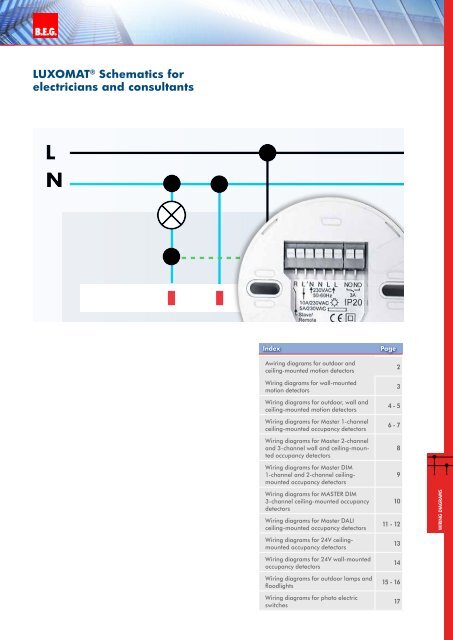
B.E.G. LUXOMAT ®wiring <strong>diagrams</strong> for outdoor, wall andceiling-mounted motion detectorsStandard mode with 1-channel motion detector (e.g. stairs)LNE1T1T2NL30 sec. 10 min.43<strong>Wiring</strong> diagram for• RC-plus next• LC-plus • LC-Click-N • LC-Mini • PD3N-1C • PD4N-1C • PD9-1CNLL΄C1Standard mode with 1-channel motion detector (e.g. stairs)LN<strong>Wiring</strong> diagram for• Indoor 180-SC+SCT1 max. 10 Indoor-SCNL30 sec. 10 min.43E1LL΄C1LL΄C1wiring <strong>diagrams</strong>4
wiring <strong>diagrams</strong> for outdoor, wall andceiling-mounted motion detectorsB.E.G. LUXOMAT ® 5Standard mode with 2-channel motion detectorLN<strong>Wiring</strong> diagram for• PD3N-2CM1 = HVAC functionE1M1NLL΄C1NO NOC2Standard mode with 2-wire technology, triacLNE1S1<strong>Wiring</strong> diagram for• Indoor 180-ToptionalS1 = switch for permanent lightLL΄C1Standard mode with 2-wire technology, relayLNE1S1<strong>Wiring</strong> diagram for• Indoor 180-R/2W-<strong>UK</strong>• Indoor 180-R-2DoptionalS1 = switch for permanent lightwiring <strong>diagrams</strong>LL΄C1
B.E.G. LUXOMAT ®wiring <strong>diagrams</strong> for Master 1-channelceiling-mounted occupancy detectorsStandard mode with Master 1-channel occupancy detectorswith R terminalLNT1E1<strong>Wiring</strong> diagram for• PD5-M-1CoptionalT1 = NO button for semi-automatic modeSlave for enlargement of detection areaRNLL΄C1RNLStandard mode with Master 1-channel occupancy detectorswith R and S terminalLNT1E1<strong>Wiring</strong> diagram for• PD9-M-1CoptionalT1 = NO button for semi-automatic modeSlave for enlargement of detection areaSNLL΄C1RRNLStandard mode with Master 1-channel occupancy detectors (NO)wiring <strong>diagrams</strong><strong>Wiring</strong> diagram for• PD9-M-1C-SDB 6
wiring <strong>diagrams</strong> for Master 1-channelceiling-mounted occupancy detectorsB.E.G. LUXOMAT ® 7Standard mode with Master 1-channel occupancy detectors (NO)with R and S terminal<strong>Wiring</strong> diagram for• PD2-M-1C• PD4-M-1CoptionalT1 = NO button for semi-automatic modeSlave for enlargement of detection area Standard mode with Master 1-channel occupancy detectors PSwith R and S terminal<strong>Wiring</strong> diagram for• PD4-M-1C-C-PSoptionalT1 = NO button for semi-automatic modeSlave for enlargement of detection area wiring <strong>diagrams</strong>
wiring <strong>diagrams</strong> for Master 2-channel and 3-channel walland ceiling-mounted occupancy detectorsB.E.G. LUXOMAT ®Standard mode with Master 2-channel occupancy detectorsLNT1 E1 M1<strong>Wiring</strong> diagram for• PD1N-M-2C • PD2-M-2C • PD4-M-2C • Indoor 180-M-2CM1 = HVAC functionRNLL΄C1NO NOC2RNLoptionalT1 = NO button for semi-automatic modeSlave for enlargement of detection areaStandard mode with Master 2-channel DUO occupancy detectorsLNT2 T1 E1 E2<strong>Wiring</strong> diagram for• PD4-M-2C-DUOoptionalT1&2 = NO button for semi-automaticmodeSlave for enlargement of detection areaSC1SC2NLL΄C1NO NOC2RRNLwiring <strong>diagrams</strong>Standard mode with Master 3-channel TRIO occupancy detectorsLNT2 T1 E1 E2 E3<strong>Wiring</strong> diagram for• PD4-M-3C-TRIOoptionalT1&2 = NO button for semiautomaticmodeSlave for enlargement ofdetection area8S S N L L΄ NO NO NO NO R R N LC1/2 C3C1 C2 C3
wiring <strong>diagrams</strong> for Master DIM 1-channel and 2-channelceiling-mounted occupancy detectorsStandard mode with Master DIM occupancy detectorsLNNL+E1110 V EB<strong>Wiring</strong>diagram for • PD1N-M-DIM• PD2-M-DIM• PD4-M-DIM• PD5-M-DIM • PD9-M-DIMT1B.E.G. LUXOMAT ® 9S N L L΄+ RR N LC1Standard mode with Master DUO DIM occupancy detectorsLN<strong>Wiring</strong>diagram for• PD4-M- DUO-DIMNL+E1110 V EBT1NL+E2110 V EBS N L L΄+ + RR N LC1C2wiring <strong>diagrams</strong>optionalT1 = NO button for semi-automatic modeSlave for enlargement of detection area
B.E.G. LUXOMAT ®wiring <strong>diagrams</strong> for MASTER DIM 3-channelceiling-mounted occupancy detectorsStandard mode with Master TRIO DIM occupancy detectorsLN<strong>Wiring</strong>diagram for• PD4-M- TRIO-DIMT1T2E3NL+E1110 VNL+E2110 VS S NO NO N L L΄ + + RR N LC1/2 C3 C3C1 C1/2 C2optionalT1&2 = NO button for semi-automatic modeSlave for enlargement of detection areawiring <strong>diagrams</strong>10
wiring <strong>diagrams</strong> for Master DALIceiling-mounted occupancy detectorsB.E.G. LUXOMAT ® 11Standard mode with Master DALI occupancy detectors<strong>Wiring</strong> diagram for• PD2-M-DALI/DSI• PD4-M-DALI/DSI• PD9-M-DALI/DSI Standard mode with Master DUO DALI occupancy detectors<strong>Wiring</strong>diagram for• PD4-M-DUO-DALI optionalT1 = NO button for semi-automatic modeSlave for enlargement of detection areawiring <strong>diagrams</strong>
B.E.G. LUXOMAT ®wiring <strong>diagrams</strong> for Master DALIceiling-mounted occupancy detectorsStandard mode with Master TRIO DALI occupancy detectors<strong>Wiring</strong>diagram for• PD4-M-TRIO-DALI optionalT1&2 = NO button for semi-automatic modeSlave for enlargement of detection areawiring <strong>diagrams</strong>12
wiring <strong>diagrams</strong> for 24 V ceiling-mounted occupancy detectorsStandard mode with Master 2-channel 24 V occupancy detectors <strong>Wiring</strong> diagram for• PD2-M-2C-24V-3A• PD2-M-2C-24V-RR B.E.G. LUXOMAT ® 13Standard mode with Master 2-channel 24 V occupancy detectors with reed relay~/+~/24VAC/DCT1X11k 15MX2<strong>Wiring</strong> diagram for• PD2-M-2C-24V-RRX1= light sensorR24V 24V~/+ ~/ ~/+NO NO NO NOC1C2R24V 24V~/+ ~/ ~/+NO NO NO NOC1C2optionalT1 = NO button for semi-automatic modeSlave for enlargement of detection areawiring <strong>diagrams</strong>
wiring <strong>diagrams</strong>B.E.G. LUXOMAT ® for 24 V wall-mounted occupancy detectorsStandard mode with 1-channel 24 V occupancy detectors<strong>Wiring</strong> diagram for• Indoor 180-R-24V-3A• Indoor 180-R-24V-RRoptionalT1 = NO button for semi-automatic modeStandard mode with 1-channel 24 V occupancy detectorswith reed relay<strong>Wiring</strong> diagram for• Indoor 180-R-24V-RRoptionalT1 = NO button for semi-automatic modeSlave for enlargement of detection area wiring <strong>diagrams</strong>14
<strong>Wiring</strong> <strong>diagrams</strong> for outdoor lamps and floodlightsStandard mode with 1-channel motion detectorLNHF-L1HF-L7HF-L8MD10LT130Ecolight AutomaticFLC150FLC500<strong>Wiring</strong> diagram for• HF-L1• MD10• LT130• Ecolight Automatic• FLC150• FLC500NLÜbersicht®Standard mode with 1-channel motion detector externalLNAL20-CdSALC-ELU/DAL20-280-BMAL20-280-BM-LEDE1 S1ALC-B-360ALC-B-360-DECOAL2-RC-plus-130/230/280FLC-280-LEDFL2-LED-230N L L´AL5-RC-plus nextC1AL5-LCAL1AL4ÜbersichtB.E.G. LUXOMAT15<strong>Wiring</strong> diagram for• HF-L7• HF-L8• HF-L11• HF-L12• AL1• AL4• AL21• AL20-CdS• ALC-ELU/D• AL20-280-BM• AL20-280-BM-LED• ALC-B-360• ALC-B-360-DECO• AL2-RC-plus-130/230/280• FLC-280-LED• FL2-LED-230• AL5-RC-plus next• AL5-LCS1 = switch for permanent lightwiring <strong>diagrams</strong>
B.E.G. LUXOMAT ®<strong>Wiring</strong> <strong>diagrams</strong> for outdoor lamps and floodlightsStandard mode with 1-channel motion detector with NC pushbuttonLNÜbersichtNT1LE1L´C1AL20-280-BMAL20-280-BM-LEDALC-B-360ALC-B-360-DECOAL2-RC-plus-130/230/280FLC-280-LEDFL2-LED-230AL5-RC-plus nextAL5-LCAL1<strong>Wiring</strong> diagram for• AL1• AL21• AL20-280-BM• AL20-280-BM-LED• ALC-B-360• ALC-B-360-DECO• AL2-RC-plus-130/230/280• FLC-280-LED• FL2-LED-230• AL5-RC-plus next• AL5-LCT1 = NC buttonManual switching additionally possible(press opener approx. 2 sec.).The position of the potentiometers shouldnot be on “test” or “sun”. If so, the pre-settime and safety values get lost.Standard mode with 1-channel motion detectorLNNLE1L´C1NLL´C1<strong>Wiring</strong> diagram for• AL1AL20-CdS• AL21ALC-ELU/D • AL20-CdSAL20-280-BM • ALC-ELU/DAL20-280-BM-LED • AL20-280-BM• AL20-280-BM-LEDALC-B-360• ALC-B-360ALC-B-360-DECO• ALC-B-360-DECOAL2-RC-plus-130/230/280• AL2-RC-plus-130/230/280FLC-280-LEDFL2-LED-230 • FLC-280-LED• FL2-LED-230AL5-RC-plus next• AL5-RC-plus nextAL5-LC• AL5-LCAL1max. 5 paralell • max. 5 parallelÜbersichtwiring <strong>diagrams</strong>16
<strong>Wiring</strong> <strong>diagrams</strong> for photo electric switchesB.E.G. LUXOMAT ®Standard mode with 1-channel photo electric switchLN17<strong>Wiring</strong> diagram for• CdS-SM• CdS-T-SM• CdS-FCE1S1S1 = switch for permanent lightNLL´C1ÜbersichtStandard mode with 1-channel photo electric switchLN<strong>Wiring</strong> diagram for• TS-DDE1max. 100m m 1.5 1,5mm²25 61Lux24 3Übersichtwiring <strong>diagrams</strong>