Downward Opening Weir Gate Specs.pdf - Plasti-Fab, Inc.
Downward Opening Weir Gate Specs.pdf - Plasti-Fab, Inc.
Downward Opening Weir Gate Specs.pdf - Plasti-Fab, Inc.

You also want an ePaper? Increase the reach of your titles
YUMPU automatically turns print PDFs into web optimized ePapers that Google loves.
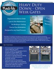
SECTION ____________DOWNWARD OPENING WEIR GATESPART 1GENERAL1.01 SUMMARYA. This Section includes all <strong>Weir</strong> <strong>Gate</strong>s required for the complete installation ofthe work.1.02 REFERENCESA. Design, fabricate and test valves and materials in accordance withmanufacturer’s recommended procedures and the following codes andstandards:1. ASTM A193 - Stainless Steel Anchor Bolts2. ASTM A276 - Stainless Steel Bars3. ASTM B584 - Alloy 865 Manganese Bronze4. ASTM D256 - Izod Impact Strength5. ASTM D570 - Water Absorption Rate6. ASTM D638 - Tensile Strength7. ASTM D695 - Compressive Properties of Rigid <strong>Plasti</strong>c8. ASTM D696 - Coefficient of Linear Expansion9. ASTM D790 - Flexural Properties10. ASTM D792 - Density and Specific Gravity at 23 0 C11. ASTM D1056 - Polymer Grade12. ASTM D2563-0 - Visual Defects13. ASTM D2583 - Indentation Hardness14. ASTM D2584 - Resin, Glass & Filler Content15. AWWA C-563 - <strong>Fab</strong>ricated Composite Slide <strong>Gate</strong>s16. AWWA C-540 - Power Actuating Devices - Sluice <strong>Gate</strong>s17. NSF-61 - Potable WaterB. Composition of the weir gate laminate shall be in accordance with therecommendations shown in the Quality Assurance Report for ReinforcedThermoset <strong>Plasti</strong>c (RTP) Corrosion Resistant Equipment prepared underthe sponsorship of the Society of the <strong>Plasti</strong>cs Industry, <strong>Inc</strong>. (SPI), and theMaterial Technology Institute (MTI) of the Chemical Process Industry for“Hand Lay-UP Laminates,” and shall meet the specifications for Type I,Grade 10 laminates shown in Appendix M-1 of said report.1
C. Manufacturer shall be experienced in the design and manufacture of specificvalves and accessories for a minimum period of 20 years.D. Manufacturer must provide warranty for 25 years against corrosion.1.03 SUBMITTALSA. Submit the following for acceptance:1. Approval Drawingsa. Showing all critical dimensions.b. Showing principal parts and materials.2. Spare parts list (when applicable).1.04 DELIVERY, STORAGE AND HANDLINGA. Ship all valves with suitable packaging to protect products from damage.B. Protect valve threads, flanges, stems and operators from damage.PART 2PRODUCTS2.01 MATERIALSA. <strong>Gate</strong> body shall be:1. Engineered composite fiberglass reinforced plastic (FRP) completelyencapsulating an internal steel reinforcing structure.a. Molded to create a seamless corrosion barrier impervious tomoisture.b. FRP resin shall be polyester / vinyl ester.c. Internal Steel Reinforcing: Carbon Steel as needed fordeflection requirements.d. Internal Core Foam: 2lb (0.9kg) polyisocyanurate closed cellrigid foam.B. Guide Frame1. Head Frame: vinyl ester resin FRP.2. Guide Frame Rails: vinyl ester resin FRP.3. Operator Support Yoke: vinyl ester resin FRP.a. Guides shall be a pultruded reinforced vinyl ester UV stabilizedfiberglass material incorporating a synthetic polymeric fibersurfacing material for high corrosion and weatherresistance. Structural characteristics in the longitudinaldirection shall meet the following physical propertiesTensile strengthFlexural ModulusFlexural StrengthImpact StrengthWater absorption30,000 psi (2109 ksc)1.3 x 10 6 psi (913991 ksc)30,000 psi (2109 ksc)20.0 ft-lbs/in. (2.77 kgf.m/25mm)0.7% (in 24 hours)C. Stems and <strong>Gate</strong> Hardware1. Stem: Type T-304L / T-316L / PREN __ super duplex stainless steel.2. <strong>Gate</strong> Hardware: Type T-304L / T-316L / PREN __ super duplexstainless steel.D. Seals1. Side, Top and Flush Bottom Seals: Hollow Bulb J Seal molded ofextruded virgin neoprene / EPDM.E. J-Seal Clamping Bar and Fasteners1. Clamping Bar: Type T-304L / T-316L / PREN __ super duplexstainless steel.2
2. Fasteners: Type T-304L / T-316L / PREN __ super duplex stainlesssteel.F. Lift Nuts and Thrust Nuts1. Manganese Bronze, ASTM B-584, Alloy 865.G. Thrust Collar1. Type T-304L / T-316L / PREN __ super duplex stainless steel.H. Handwheel1. Cast Iron, ASTM A-126, Class B.I. Anchor Bolts1. Type T-304L / T-316L / PREN __ super duplex stainless steel.J. Stem Cover1. Butyrate (manual handwheel).2. Clear PVC (Electric Motor Operators).K. Stem Guides (When applicable)1. UHMW2.02 WEIR GATESA. Acceptable Manufacturers:1. <strong>Plasti</strong>-<strong>Fab</strong> <strong>Inc</strong>a. Shall be Model No. WG_______(width x height of channel).2. Or approved equal. Pre-approved by Engineer at least 10 businessdays prior to bid date.a. Manufacturer must have a qualified Engineer on staff with atleast 5 years experience with hydraulic control gates.B. <strong>Gate</strong> valves shall exceed AWWA C-563:1. Leakage:a. Valves shall have a maximum leakage rate of 0.10 GPM/ft(1.24 LPM/m) of wetted linear seal under seating andunseating head pressures under full design head and shallprovide adjustment to zero leakage.b. <strong>Weir</strong> gate shall be wedging and have adjusting bolts to allow fora zero leakage rate.2.03 DESIGN CRITERIAA. Composition of the weir gate laminate shall be in accordance with therecommendations shown in the Quality Assurance Report for ReinforcedThermostat <strong>Plasti</strong>c (RTP) Corrosion Resistant Equipment preparedunder the sponsorship the Society of the <strong>Plasti</strong>cs Industry, <strong>Inc</strong>. (SPI) andthe Material Technology Institute of the Chemical Process Industries, <strong>Inc</strong>.(MTI) for “Hand Lay-up Laminates” and shall meet the specifications forType 1, Grade 10 laminates shown in Appendix M-1 of said report.1. Visual inspection for defects shall be made without the aid ofmagnification and defects shall be classified as to type and level asshown in Table 1 of ANSI/ASTM D2563-0, approved 1977, (or anysubsequent revision). Allowable surface tolerances are as follows:DEFECTSCracksCrazingBlistersChipsPitsALLOWABLE TOLERANCENone3
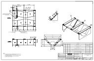
Dry SpotsFish EyesBurned AreasEntrapped AirWrinkles and solid blisters, not toexceed 1/8”Surface porosity (pinholes orpores in the laminate surface)Exposed GlassExposure of cut edgesScratchesForeign MatterMaximum Deviation: 10% ofthicknessNoneNoneNone more than .002” deep(.05mm)NoneB. Maximum Fiber Stress1. Ultimate or yield, whichever applies, does not exceed 2.5 times theworking stress.C. Deflection1. Deflection across the gate width shall be limited to: L/360 or ¼”(6mm), whichever is less, at the maximum operating head.D. Head Pressure1. <strong>Gate</strong> shall be designed for a maximum head pressure of: __________inches / millimeters.E. <strong>Gate</strong> Size1. <strong>Gate</strong> Width: ___________ inches / millimeters.2. <strong>Gate</strong> Height: ___________ inches / millimeters.3. <strong>Gate</strong> Invert Elevation: ___________ inches / millimeters.4. Top of Wall Elevation: ____________ inches / millimeters.F. Surface Conditions1. All weir gates shall be flat and level.2. Warpage throughout the entire gate shall not produce a crown ofmore than 1/16” (1.6mm) in any direction.3. <strong>Gate</strong>s having reinforcing members bolted or bonded to flat sheetstock will not be acceptable.2.04 CONSTRUCTIONA. <strong>Gate</strong> Body1. <strong>Weir</strong> gate body shall be manufactured of fiberglass reinforcedpolyester totally encapsulating an internal reinforcing structure.2. <strong>Weir</strong> gates shall be manufactured of reinforced thermoset plastic.3. <strong>Gate</strong> body shall have UV Stabilizing pigment in the Resin to providelong-term protection from UV.4. The surface shall be resin rich to a depth of .010 inches to .020 inches(.25 - .51mm) and reinforced with C-glass and/or polymeric fibersurfacing material.5. The surface shall be free of exposed reinforcing fibers.6. The composition of these layers shall be approximately 95% (byweight) resin. The remaining laminate shall be made up ofcopolymer composite and reinforcing fibers in a form, orientationand position to meet the mechanical requirements.7. Structural reinforcing shall be utilized to attain the necessary stiffnessto meet deflection requirements, and shall be well encapsulatedwith a laminate not less than 1/4” (6mm) thick on each side toensure against any permeation by water to the core areas.4
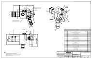
8. A Type T-304L / T-316L / PREN __ super duplex stainless steel stemmounting bracket shall fasten to the gate with through bolts. Thethrough holes shall not pass through or be in contact with theinternal mild steel reinforcing.9. Core material must be 100% resistant to decay and attack by fungusand bacteria and be resistant to hydrocarbons.10. Each gate shall be molded individually to the exact dimensionsspecified. Seams and joints in and on the disc are not acceptable.11. Down opening weir gates shall have a spigot back and side angles atthe channel invert that form a straight and level mating surface forthe gate to pass over.B. Seals1. The gate shall be equipped with elastomeric seals to reduce leakage.2. Elastomeric J-seals shall be made of molded or extruded neoprene /EPDM having a hardness range of 55 to 65 shore A durometerand conforming to ASTM spec. D-2000 having a maximumcompression set of 25%, and low temperature brittleness to meetsuffix F-17 (-40 0 ).3. Seals, including bottom seals, shall be mounted on gate covers withtype T-304L / T-316L / PREN __ super duplex stainless steel capscrews and type T-304L / T-316L / PREN __ super duplexstainless steel or FRP clamping bars thus providing a means ofrepair, and replacement without dewatering the channel.C. Frames and Guides1. Guides shall be styled for embedment / wall mounting / in-channelmounting as shown on the contract drawings and/or gateschedule.2. Guides shall be fabricated from vinyl ester resin and shall have a slotsuitable for mating with the gate body.3. Where self-contained guides are extended above the operating floorlevel to form the bench stand upon which the lift mechanism isfastened, they must be suitably strong and rigid without the use ofadditional stiffening members.4. The head rail shall be affixed so as to allow the gate to be removedfrom the guide without disassembly.5. The head rail shall have a maximum deflection of 1/4” (6mm) whensubjected to a horizontal force of four times the 40 lb. (2.8 ksc)maximum hand wheel pull.6. Where a wall mounted guide frame extends above a concrete wall thetop anchor bolt shall be not more than 6” (152mm) below the top ofthe wall.7. <strong>Gate</strong> inverts shall be flush with the channel bottom.8. If the <strong>Gate</strong> width is greater than 2x the gate height, a tandem stemshall be used.9. Guide Frame shall extend beyond the invert at least ¾ of the distanceof the gate travel.10. No wall thimbles shall be required for installation.D. Lifts & Operators1. Operators shall be sized to start the gate moving under a maximumhead pressure with a pull of not more than 40 lbs (2.8 ksc).2. A manual hand wheel / crank shall be supplied that is compatible withthe lift.E. Electric, pneumatic or hydraulic Operators (OPTIONAL)1. <strong>Gate</strong> Manufacturer shall provide actuators per Electric Motor OperatorManufacturer’s recommended sizes based on Operating Forces5
and design requirements and shall be for open/close / modulatingservice.F. Operating Stems1. Each HDTS gate/penstock shall be equipped with a rising / non-risingoperating stem. The stem shall be Type 304L / 316L / PREN __super duplex stainless steel stainless steel.2. The stem will have Acme threads and shall be provided withadjustable stop collars to limit upward and downward travel.3. Stems shall have a maximum L/R of 200.4. Stem guides with bronze or FRP bushings shall be used to maintainan L/R of 200.G. Stem Covers1. Transparent plastic stem covers shall be provided with vent holes tominimize condensation.2. The stem covers shall be marked with `Open’ and `Closed’ positionindicators.H. Pedestals1. For non self-contained guide frames a floor / wall mounted pedestalshall be furnished for mounting the operator.2. Pedestal material shall be type T-304L / T-316L / PREN __ superduplex stainless steel.2.05 PHYSICAL PROPERTIESA. Structural characteristics for a 1/8” (3mm) glass mat laminate shall meet thefollowing minimum physical properties:Tensile strengthFlexural ModulusFlexural StrengthCompressive StrengthImpact StrengthWater absorption15,000 psi (1034 ksc)1,000,000 psi (70307 ksc)20,000 psi (1406 ksc)22,000 psi (1547 ksc)9.0 ft-lbs/in.(1.24 kgf.m/25mm)0.13% (in 24 hours)B. Seals: Extruded Virgin Neoprene EPDM Seals shall have the followingphysical characteristics:Specific Gravity 1.25Hardness55 – 65 Shore A DurometerTensile Strength1500 psi min. (0.07ksc)Elongation 300%Low temperature brittleness - 40C. Wear Strips UHMW Polyethylene:Tensile Strength 5,600 psi (0.7kg/cm 2 )Flexural Modulus @ 73 0 F (23 0 C) 130,000 – 140,000 psi(9140 – 9843kg/cm 2 )Coefficient of Friction 0.15Water Absorption0.01% in 24 hours6
PART 3EXECUTION3.01 INSTALLATIONA. Thoroughly clean and remove all shipping materials prior to setting.B. Install <strong>Gate</strong>s per Manufacturer’s recommendations.C. Operate all valves from fully opened to totally closed.3.02 FIELD TESTING (OPTIONAL)A. Qualified Factory representative shall provide (8) hours of training forfacility employees. (Optional)B. Representative shall complete a Certification of Proper Installation and providecopies to the Owner, Engineer, Contractor and Manufacturing Facility.(When applicable)END OF SECTION7